Downloaded 148 times
![Tallinn Technical University :: May 4th 2009 This presentation is available at http://www.slideshare.net/josemmf Tallinn Technical University :: May 4th 2009 This presentation is available at http://www.slideshare.net/josemmf J. M. Martins Ferreira FEUP / DEEC - Rua Dr. Roberto Frias 4200-537 Porto - PORTUGAL Tel. 351 225 081 889 / Fax: 351 225 081 443 [ jmf@fe.up.pt ] Boundary-scan test for structural fault detection](https://image.slidesharecdn.com/tallinn-2009-090427133943-phpapp02/75/The-IEEE-1149-1-Boundary-scan-test-standard-1-2048.jpg)


![Tallinn Technical University :: May 4th 2009 This presentation is available at http://www.slideshare.net/josemmf Tallinn Technical University :: May 4th 2009 This presentation is available at http://www.slideshare.net/josemmf Boundary-scan test for structural fault detection Thanks for your attention! J. M. Martins Ferreira [ jmf@fe.up.pt ]](https://image.slidesharecdn.com/tallinn-2009-090427133943-phpapp02/75/The-IEEE-1149-1-Boundary-scan-test-standard-32-2048.jpg)

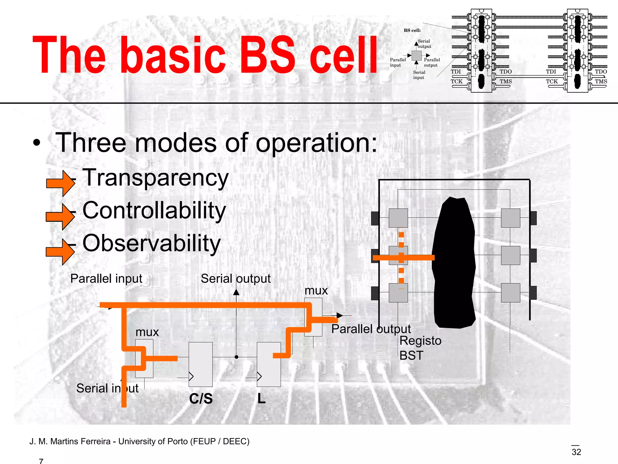
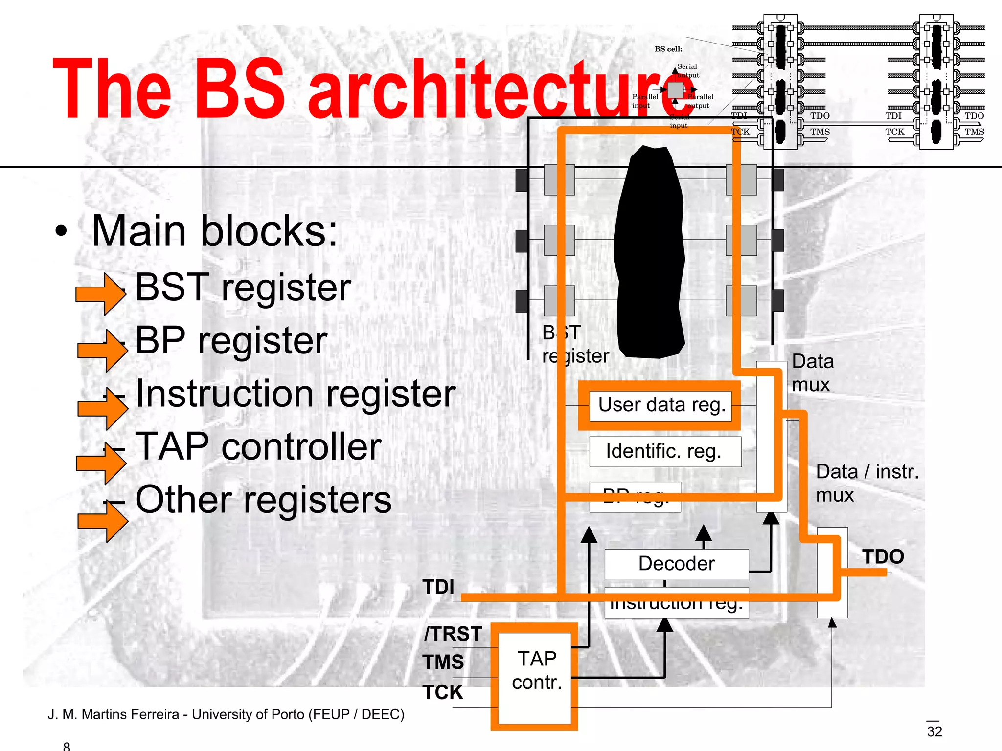
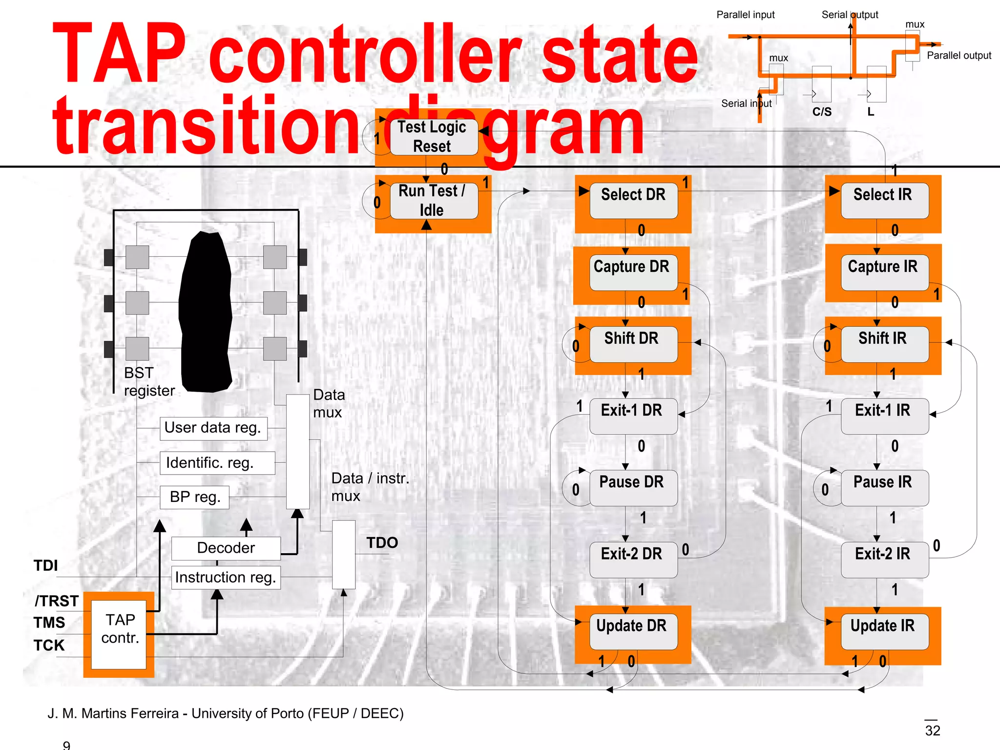
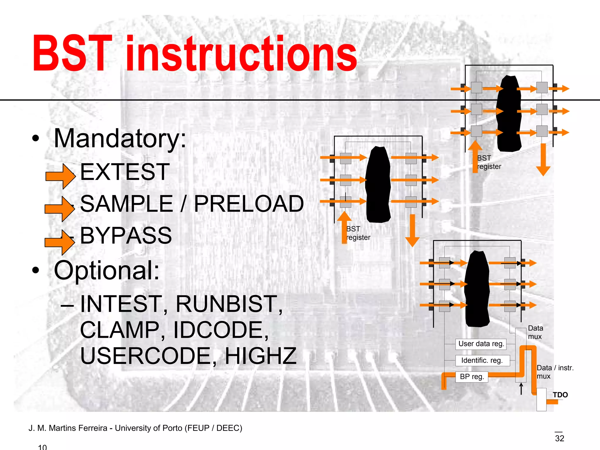
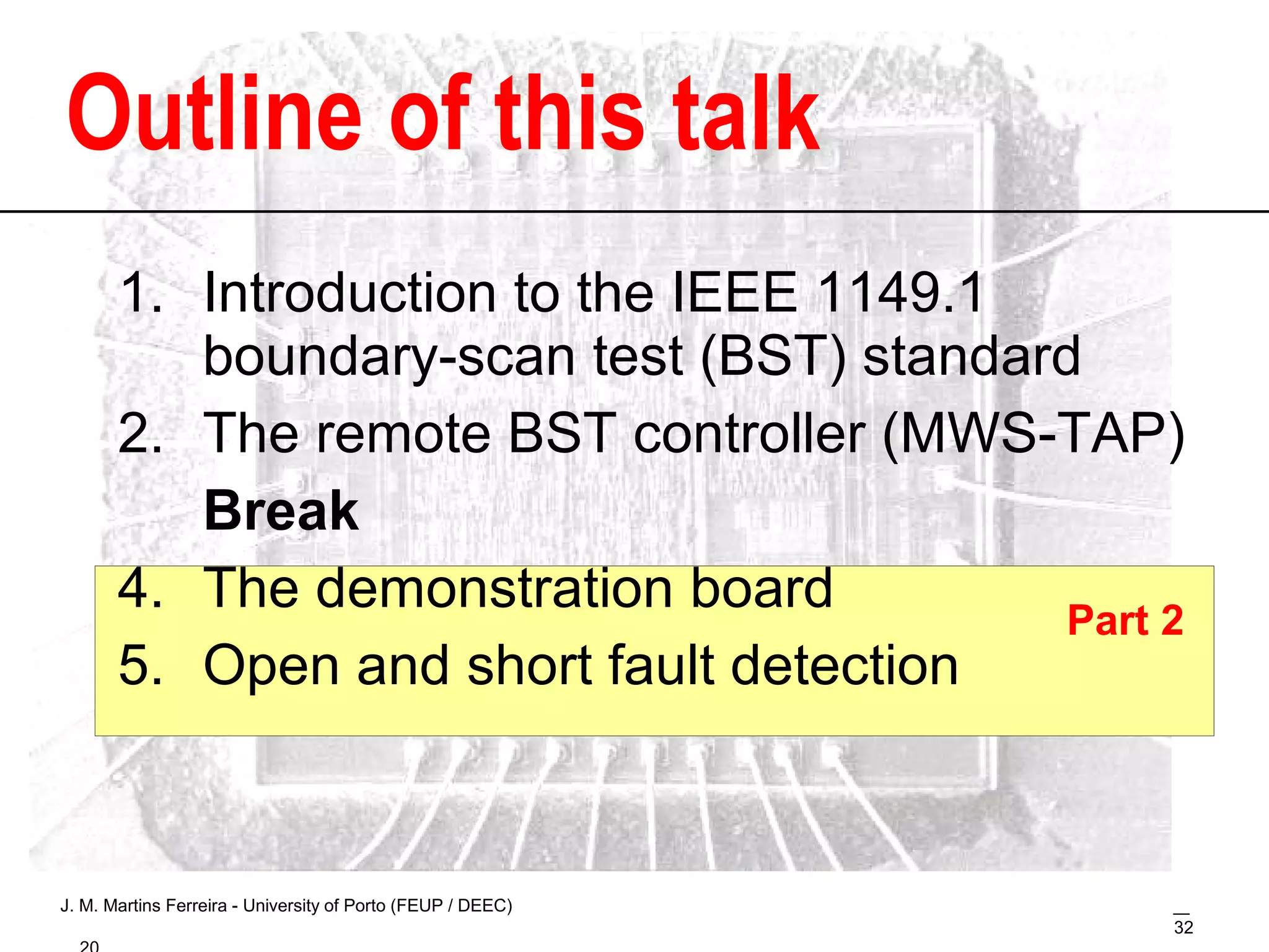
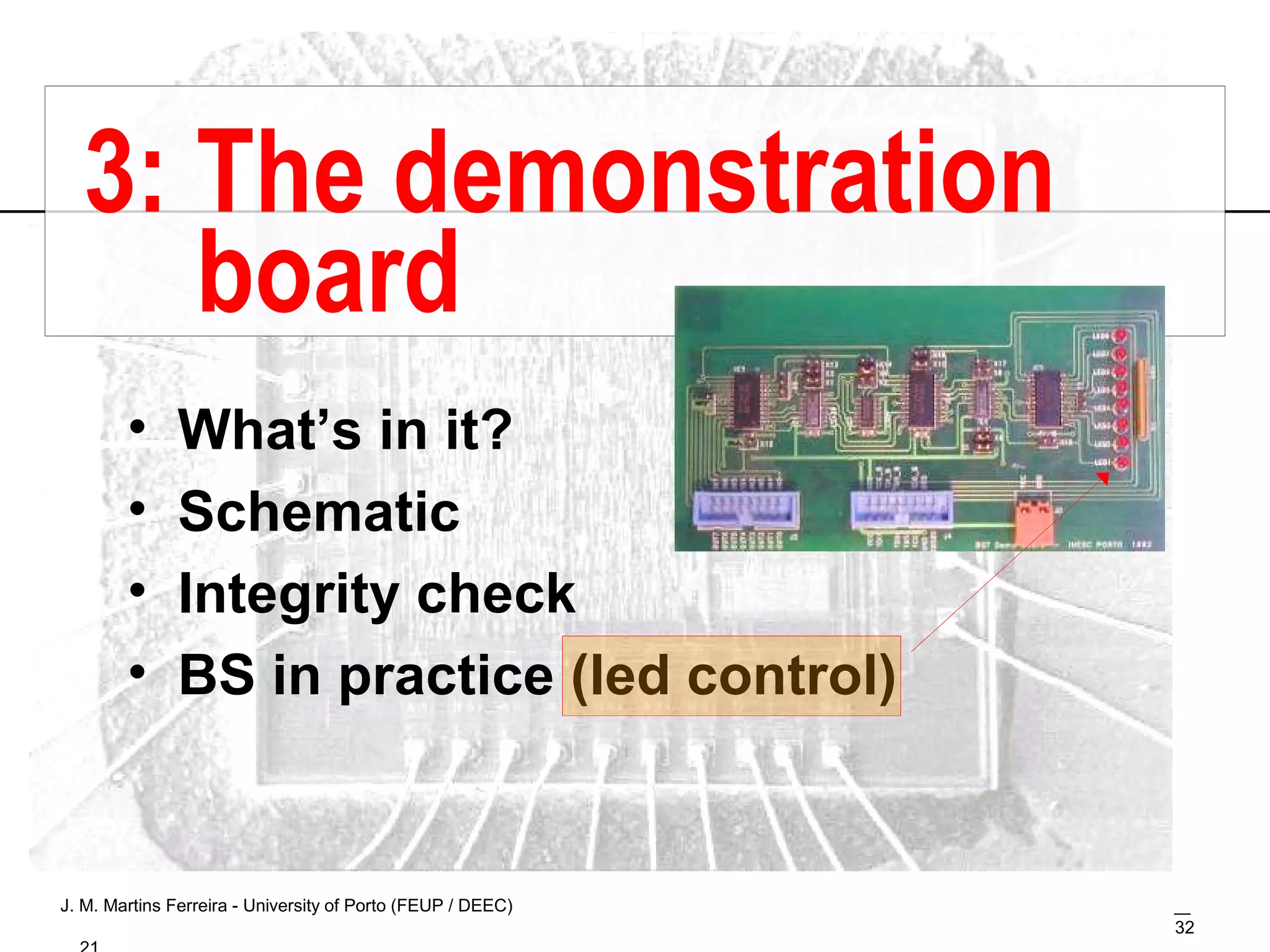
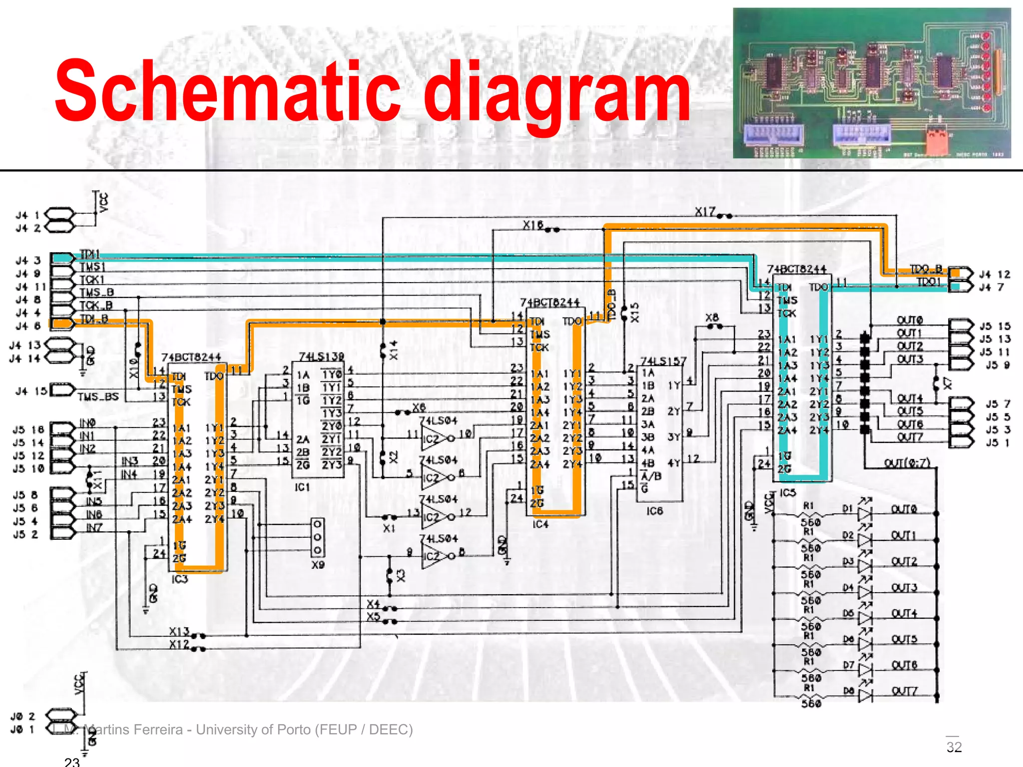
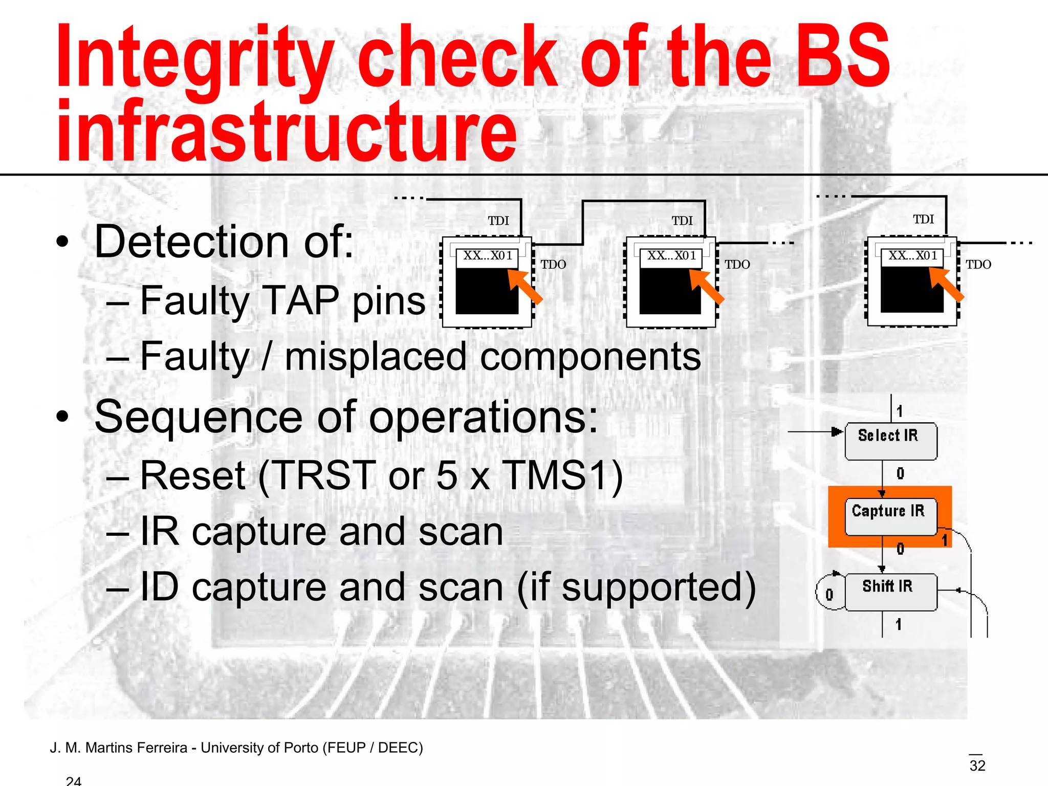
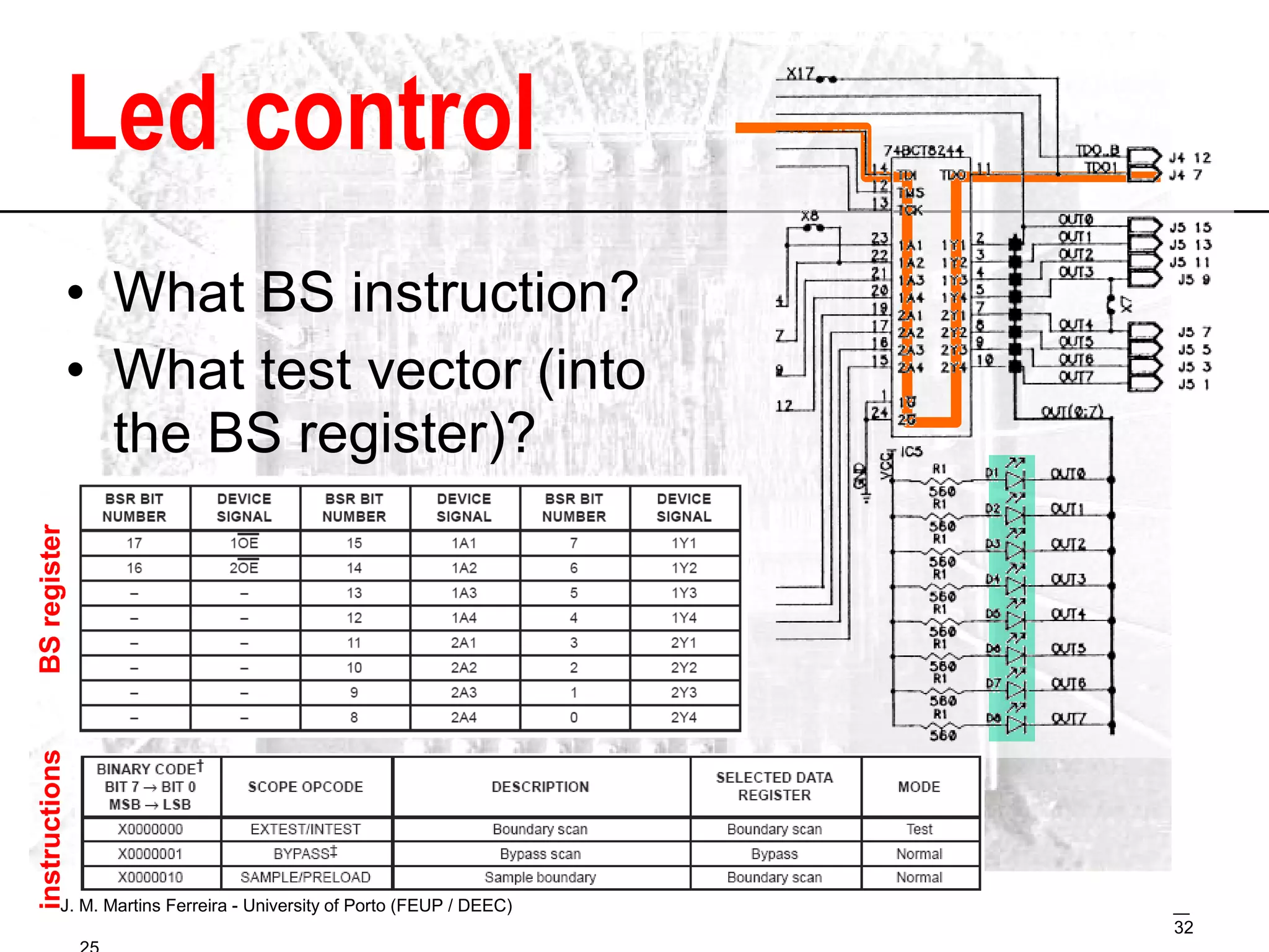
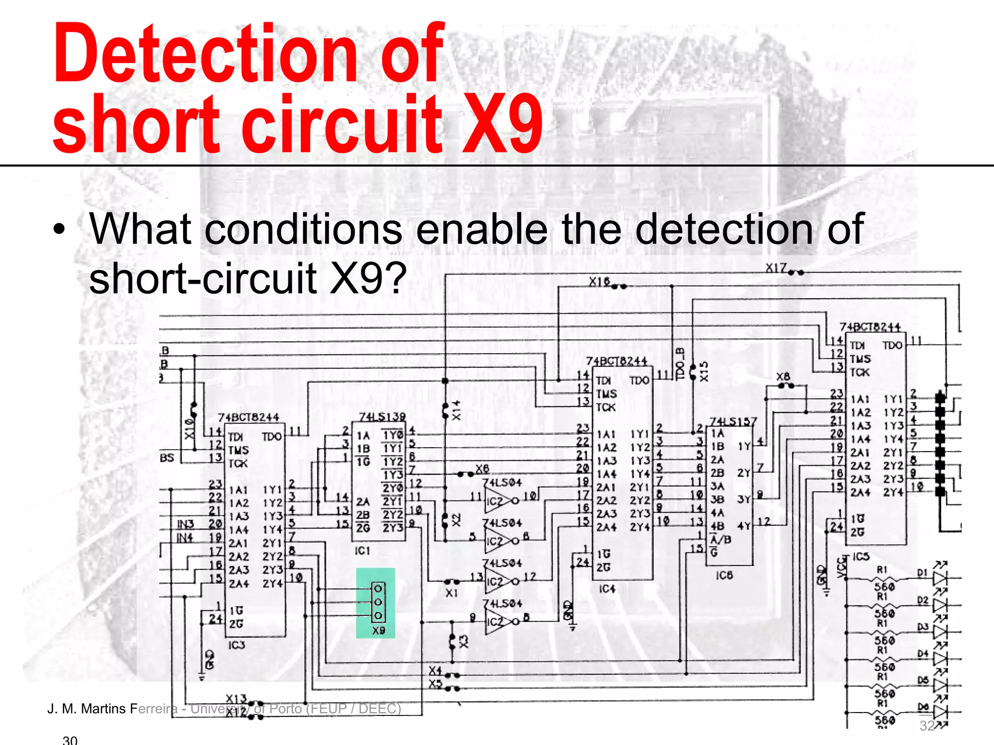
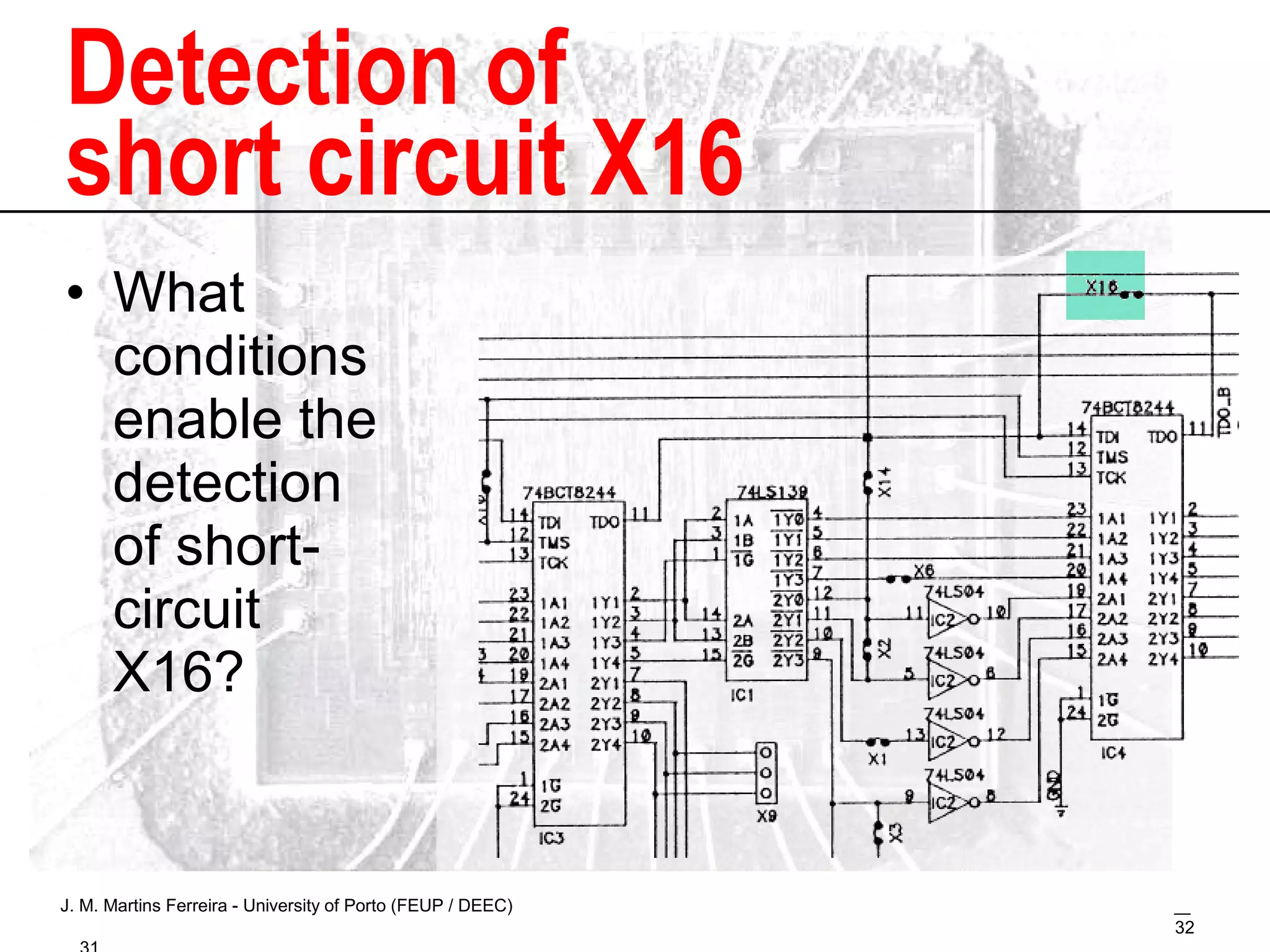
This document presents a detailed overview of the IEEE 1149.1 Boundary-Scan Test (BST) standard and its application for structural fault detection in digital printed circuit boards. It discusses the test architecture, necessary components, and practical hands-on exercises using a remote BST controller setup. The content aims to provide both theoretical knowledge and practical skills for students in hardware testing and diagnostics.


![Design for Test [DFT]-1 (1).pdf DESIGN DFT](https://cdn.slidesharecdn.com/ss_thumbnails/designfortestdft-11-231227151941-28a508a3-thumbnail.jpg?width=640&height=640&fit=bounds)