The document discusses automatic synchronization of generators, including:
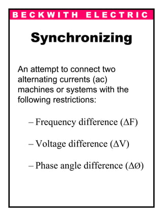
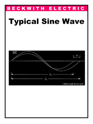
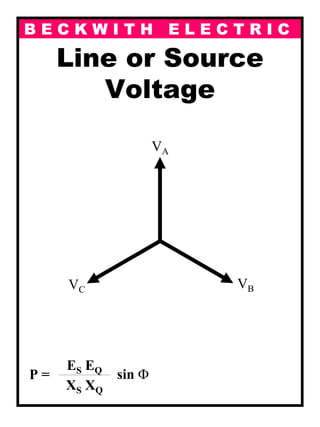
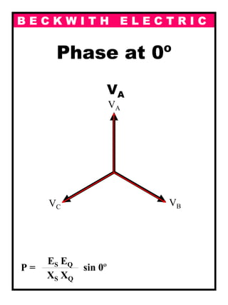
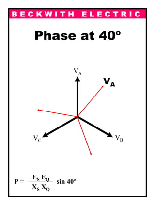
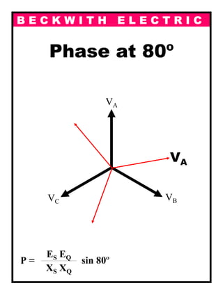
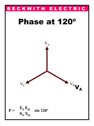
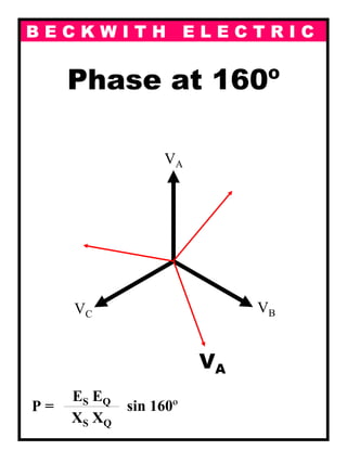
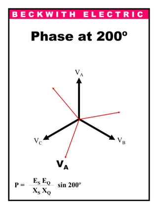
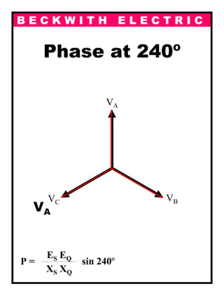
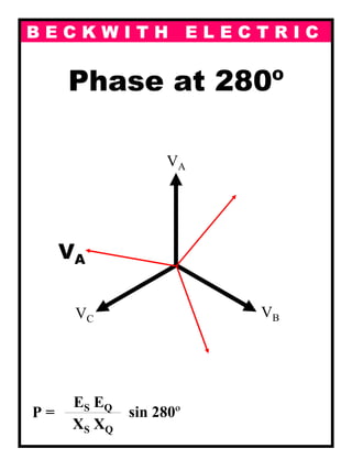
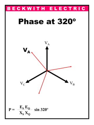
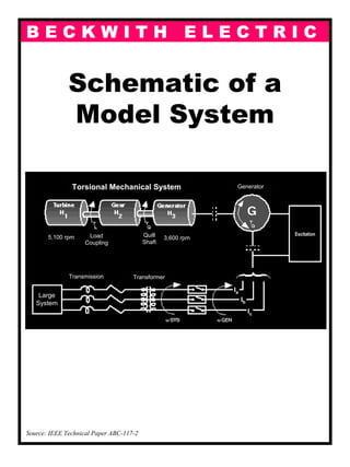
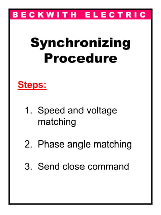
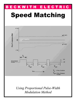
1) Synchronization involves matching the frequency, voltage, and phase angle between two AC power sources or systems before connecting them.
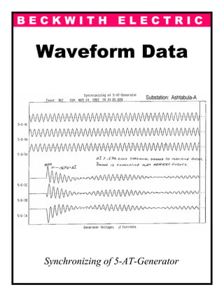
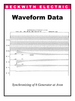
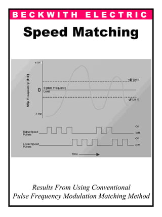
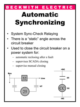
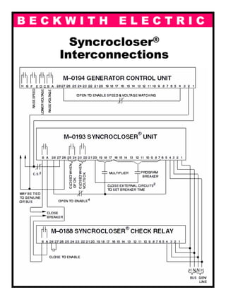
2) Synchronization is achieved through automatic synchronizers that monitor these parameters and send a close signal once matching conditions are met.
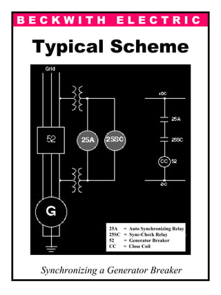
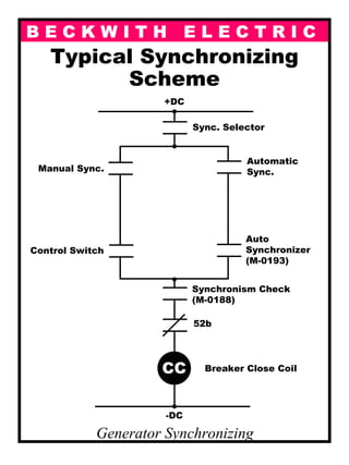
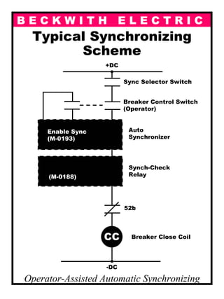
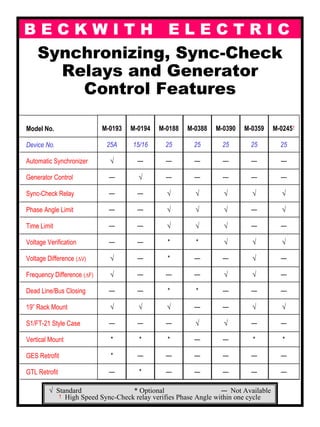
3) Typical synchronization schemes involve an automatic synchronizer relay, sync-check relay, and circuit breaker that are coordinated to safely connect the generators.
Excitation System & capability curve of synchronous generatorMANOJ KUMAR MAHARANA
Excitation systems perform control and protective functions essential to the satisfactory performance of the power system.
The amount of continuous reactive power a generator can supply is restricted by various limits. In the over-excitation region limits are imposed by rotor heating or amount of field current and second is the stator current. In the under excitation region the limits are imposed by load angle. So in steady state the generator should always operate within this region and the loci of the various limiters are called the capability curve of the generator.
Functions and Performance Requirements
Elements of an Excitation System
Types of Excitation Systems
Control and Protection Functions
Modeling of Excitation Systems
The functions of an excitation system are
to provide direct current to the synchronous generator field winding, and
to perform control and protective functions essential to the satisfactory operation of the power system
The performance requirements of the excitation system are determined by
Generator considerations:
supply and adjust field current as the generator output varies within its continuous capability
respond to transient disturbances with field forcing consistent with the generator short term capabilities:
rotor insulation failure due to high field voltage
rotor heating due to high field current
stator heating due to high VAR loading
heating due to excess flux (volts/Hz)
Power system considerations:
contribute to effective control of system voltage and improvement of system stability
This presentation is about power system voltage stability.
What is voltage stability?
How voltage instability occurs?
How to improve voltage stability of the system?
This presentation is about power system voltage stability.
What is voltage stability?
How voltage instability occurs?
How to improve voltage stability of the system?
An uninterruptible power supply, also uninterruptible power source, UPS or battery/flywheel backup, is an electrical apparatus that provides emergency power to a load when the input power source, typically mains power, fails. A UPS differs from an auxiliary or emergency power system or standby generator in that it will provide near-instantaneous protection from input power interruptions, by supplying energy stored in batteries, supercapacitors, or flywheels.
Design of Industrial Automation Functional Specifications for PLCs, DCs and S...Living Online
This manual will be useful to both specifiers and implementers providing a theoretical grounding for preparing a control system functional specification for implementation on Industrial control systems consisting of PLC (Programmable Logic Controllers), HMI (Human Machine Interfaces / SCADA devices) or DCS (Distributed Control Systems).
FOR MORE INFORMATION: http://www.idc-online.com/content/design-industrial-automation-functional-specifications-plcs-dcss-and-scada-systems-15
A Novel Single-Phase AC-AC Converter for Circuit Breaker Testing Appli...ANU143SRA
This Project a novel single-phase ac-ac converter with power factor correction and output current control for circuit-breaker testing according to the IEC 60898 standard. The important advantages of the proposed circuit are low component count and fast responses for the standard requirement, especially a current step at the beginning of the test. The proposed single-phase ac-ac converter can operate in either buck or boost mode to accommodate the need for a wide range of output current while satisfying the ramping and step current requirements in the standard. The control circuits consist of two parts, dc voltage control of dc-link capacitors and ac output current controls operating simultaneously. The proposed circuit is verified through both computer simulation and hardware experiment. An example of a 50A circuit breaker testing according to the IEC 60898 is demonstrated in the project.
The International Journal of Engineering & Science is aimed at providing a platform for researchers, engineers, scientists, or educators to publish their original research results, to exchange new ideas, to disseminate information in innovative designs, engineering experiences and technological skills. It is also the Journal's objective to promote engineering and technology education. All papers submitted to the Journal will be blind peer-reviewed. Only original articles will be published.
CFD Simulation of By-pass Flow in a HRSG module by R&R Consult.pptxR&R Consult
CFD analysis is incredibly effective at solving mysteries and improving the performance of complex systems!
Here's a great example: At a large natural gas-fired power plant, where they use waste heat to generate steam and energy, they were puzzled that their boiler wasn't producing as much steam as expected.
R&R and Tetra Engineering Group Inc. were asked to solve the issue with reduced steam production.
An inspection had shown that a significant amount of hot flue gas was bypassing the boiler tubes, where the heat was supposed to be transferred.
R&R Consult conducted a CFD analysis, which revealed that 6.3% of the flue gas was bypassing the boiler tubes without transferring heat. The analysis also showed that the flue gas was instead being directed along the sides of the boiler and between the modules that were supposed to capture the heat. This was the cause of the reduced performance.
Based on our results, Tetra Engineering installed covering plates to reduce the bypass flow. This improved the boiler's performance and increased electricity production.
It is always satisfying when we can help solve complex challenges like this. Do your systems also need a check-up or optimization? Give us a call!
Work done in cooperation with James Malloy and David Moelling from Tetra Engineering.
More examples of our work https://www.r-r-consult.dk/en/cases-en/
Saudi Arabia stands as a titan in the global energy landscape, renowned for its abundant oil and gas resources. It's the largest exporter of petroleum and holds some of the world's most significant reserves. Let's delve into the top 10 oil and gas projects shaping Saudi Arabia's energy future in 2024.
Cosmetic shop management system project report.pdfKamal Acharya
Buying new cosmetic products is difficult. It can even be scary for those who have sensitive skin and are prone to skin trouble. The information needed to alleviate this problem is on the back of each product, but it's thought to interpret those ingredient lists unless you have a background in chemistry.
Instead of buying and hoping for the best, we can use data science to help us predict which products may be good fits for us. It includes various function programs to do the above mentioned tasks.
Data file handling has been effectively used in the program.
The automated cosmetic shop management system should deal with the automation of general workflow and administration process of the shop. The main processes of the system focus on customer's request where the system is able to search the most appropriate products and deliver it to the customers. It should help the employees to quickly identify the list of cosmetic product that have reached the minimum quantity and also keep a track of expired date for each cosmetic product. It should help the employees to find the rack number in which the product is placed.It is also Faster and more efficient way.
Sachpazis:Terzaghi Bearing Capacity Estimation in simple terms with Calculati...Dr.Costas Sachpazis
Terzaghi's soil bearing capacity theory, developed by Karl Terzaghi, is a fundamental principle in geotechnical engineering used to determine the bearing capacity of shallow foundations. This theory provides a method to calculate the ultimate bearing capacity of soil, which is the maximum load per unit area that the soil can support without undergoing shear failure. The Calculation HTML Code included.
About
Indigenized remote control interface card suitable for MAFI system CCR equipment. Compatible for IDM8000 CCR. Backplane mounted serial and TCP/Ethernet communication module for CCR remote access. IDM 8000 CCR remote control on serial and TCP protocol.
• Remote control: Parallel or serial interface.
• Compatible with MAFI CCR system.
• Compatible with IDM8000 CCR.
• Compatible with Backplane mount serial communication.
• Compatible with commercial and Defence aviation CCR system.
• Remote control system for accessing CCR and allied system over serial or TCP.
• Indigenized local Support/presence in India.
• Easy in configuration using DIP switches.
Technical Specifications
Indigenized remote control interface card suitable for MAFI system CCR equipment. Compatible for IDM8000 CCR. Backplane mounted serial and TCP/Ethernet communication module for CCR remote access. IDM 8000 CCR remote control on serial and TCP protocol.
Key Features
Indigenized remote control interface card suitable for MAFI system CCR equipment. Compatible for IDM8000 CCR. Backplane mounted serial and TCP/Ethernet communication module for CCR remote access. IDM 8000 CCR remote control on serial and TCP protocol.
• Remote control: Parallel or serial interface
• Compatible with MAFI CCR system
• Copatiable with IDM8000 CCR
• Compatible with Backplane mount serial communication.
• Compatible with commercial and Defence aviation CCR system.
• Remote control system for accessing CCR and allied system over serial or TCP.
• Indigenized local Support/presence in India.
Application
• Remote control: Parallel or serial interface.
• Compatible with MAFI CCR system.
• Compatible with IDM8000 CCR.
• Compatible with Backplane mount serial communication.
• Compatible with commercial and Defence aviation CCR system.
• Remote control system for accessing CCR and allied system over serial or TCP.
• Indigenized local Support/presence in India.
• Easy in configuration using DIP switches.
Design and Analysis of Algorithms-DP,Backtracking,Graphs,B&B
Automatic synch of gen
1. B E C K W I T H E L E C T R I C
Automatic
Synchronizing of
Generators
Automatic
Synchronizing of
Generators
Theory and ApplicationTheory and Application
2. B E C K W I T H E L E C T R I C
Synchronizing
An attempt to connect two
alternating currents (ac)
machines or systems with the
following restrictions:
– Frequency difference (∆F)
– Voltage difference (∆V)
– Phase angle difference (∆Ø)
3. B E C K W I T H E L E C T R I C
Typical Sine Wave
4. B E C K W I T H E L E C T R I C
Line or Source
Voltage
P =
ES EQ---------------------------------------------------------------
XS XQ
sin Φ
VA
VBVC
5. B E C K W I T H E L E C T R I C
Phase at 0º
P =
ES EQ---------------------------------------------------------------
XS XQ
sin 0º
VA
VBVC
VA
6. B E C K W I T H E L E C T R I C
Phase at 40º
P =
ES EQ---------------------------------------------------------------
XS XQ
sin 40º
VA
VBVC
VA
7. B E C K W I T H E L E C T R I C
Phase at 80º
P =
ES EQ---------------------------------------------------------------
XS XQ
sin 80º
VA
VBVC
VA
8. B E C K W I T H E L E C T R I C
Phase at 120º
P =
ES EQ---------------------------------------------------------------
XS XQ
sin 120º
VA
VBVC
VA
9. B E C K W I T H E L E C T R I C
Phase at 160º
P =
ES EQ---------------------------------------------------------------
XS XQ
sin 160º
VA
VBVC
VA
10. B E C K W I T H E L E C T R I C
Phase at 200º
P =
ES EQ---------------------------------------------------------------
XS XQ
sin 200º
VA
VBVC
VA
11. B E C K W I T H E L E C T R I C
Phase at 240º
P =
ES EQ---------------------------------------------------------------
XS XQ
sin 240º
VA
VBVC
VA
12. B E C K W I T H E L E C T R I C
Phase at 280º
P =
ES EQ---------------------------------------------------------------
XS XQ
sin 280º
VA
VBVC
VA
13. B E C K W I T H E L E C T R I C
Phase at 320º
P =
ES EQ---------------------------------------------------------------
XS XQ
sin 320º
VA
VBVC
VA
14. B E C K W I T H E L E C T R I C
Waveform Data
Synchronizing of 5-AT-Generator
15. B E C K W I T H E L E C T R I C
Waveform Data
Synchronizing of 6 Generator at Avon
16. B E C K W I T H E L E C T R I C
Typical Scheme
Synchronizing a Generator Breaker
25A = Auto Synchronizing Relay
25SC = Sync-Check Relay
52 = Generator Breaker
CC = Close Coil
17. B E C K W I T H E L E C T R I C
Schematic of a
Model System
Source: IEEE Technical Paper ABC-117-2
Torsional Mechanical System Generator
Excitation
Transmission Transformer
Large
System
Load
Coupling
Quill
Shaft
3,600 rpm5,100 rpm
Ia
Ib
Ic
18. B E C K W I T H E L E C T R I C
Synchronizing
Procedure
Steps:
1. Speed and voltage
matching
2. Phase angle matching
3. Send close command
19. B E C K W I T H E L E C T R I C
Typical Synchronizing
Scheme
Generator Synchronizing
CC
-DC
+DC
Sync. Selector
Automatic
Sync.
Auto
Synchronizer
(M-0193)
Synchronism Check
(M-0188)
52b
Breaker Close Coil
Manual Sync.
Control Switch
20. B E C K W I T H E L E C T R I C
Speed Matching
Results From Using Conventional
Pulse Frequency Modulation Matching Method
21. B E C K W I T H E L E C T R I C
Speed Matching
Using Proportional Pulse-Width
Modulation Method
TBP TBP
TBP
22. B E C K W I T H E L E C T R I C
Typical Synchronizing
Scheme
Operator-Assisted Automatic Synchronizing
CC
-DC
+DC
Sync Selector Switch
Auto
Synchronizer
Synch-Check
Relay
52b
Breaker Close Coil
Breaker Control Switch
(Operator)
Enable Sync
(M-0193)
(M-0188)
23. B E C K W I T H E L E C T R I C
Automatic
Synchronizing
• System Sync-Check Relaying
• There is a “static” angle across the
circuit breaker
• Used to close the circuit breaker on a
power system for:
– automatic reclosing after a fault
– supervises SCADA closing
– supervise manual closing
52
25
Bus
Line
VT
+DC
-DC
CC
25
52
24. B E C K W I T H E L E C T R I C
Syncrocloser®
Interconnections
25. B E C K W I T H E L E C T R I C
Synchronizing, Sync-Check
Relays and Generator
Control Features
Model No.
Device No.
Automatic Synchronizer
Generator Control
Sync-Check Relay
Phase Angle Limit
Time Limit
Voltage Verification
Voltage Difference (∆V)
Frequency Difference (∆F)
Dead Line/Bus Closing
19” Rack Mount
S1/FT-21 Style Case
Vertical Mount
GES Retrofit
GTL Retrofit
M-0193
25A
√
—
—
—
—
—
√
√
—
√
—
*
*
—
M-0194
15/16
—
√
—
—
—
—
—
—
—
√
—
*
—
*
M-0188
25
—
—
√
√
√
*
*
—
*
√
—
*
—
—
M-0388
25
—
—
√
√
√
*
—
—
*
—
√
—
—
—
M-0245†
25
—
—
√
√
—
√
—
—
—
√
—
*
—
—
M-0359
25
—
—
√
—
—
√
√
√
—
√
—
*
—
—
M-0390
25
—
—
√
√
√
√
—
√
—
—
√
—
—
—
√ Standard * Optional — Not Available
† High Speed Sync-Check relay verifies Phase Angle within one cycle