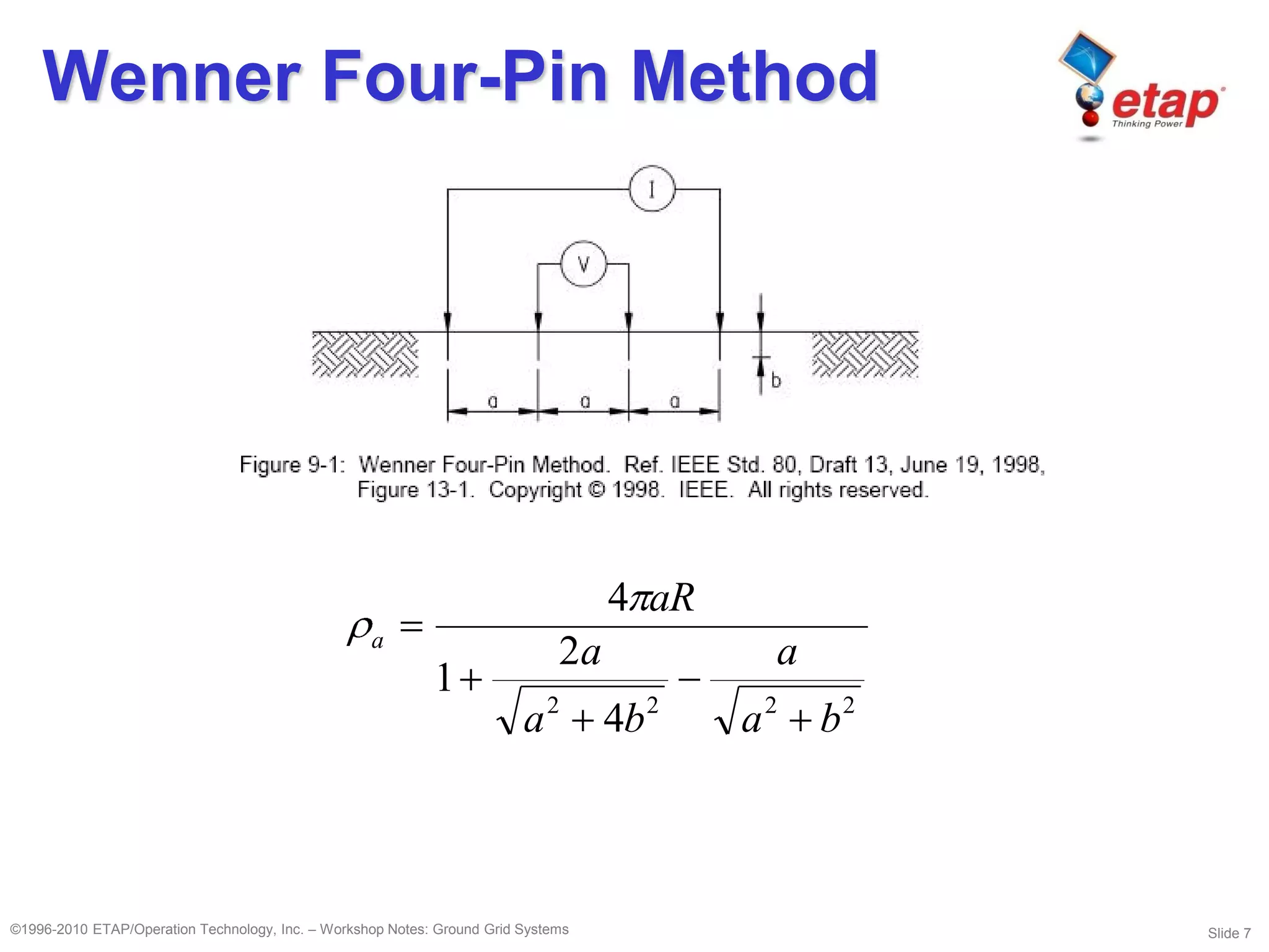
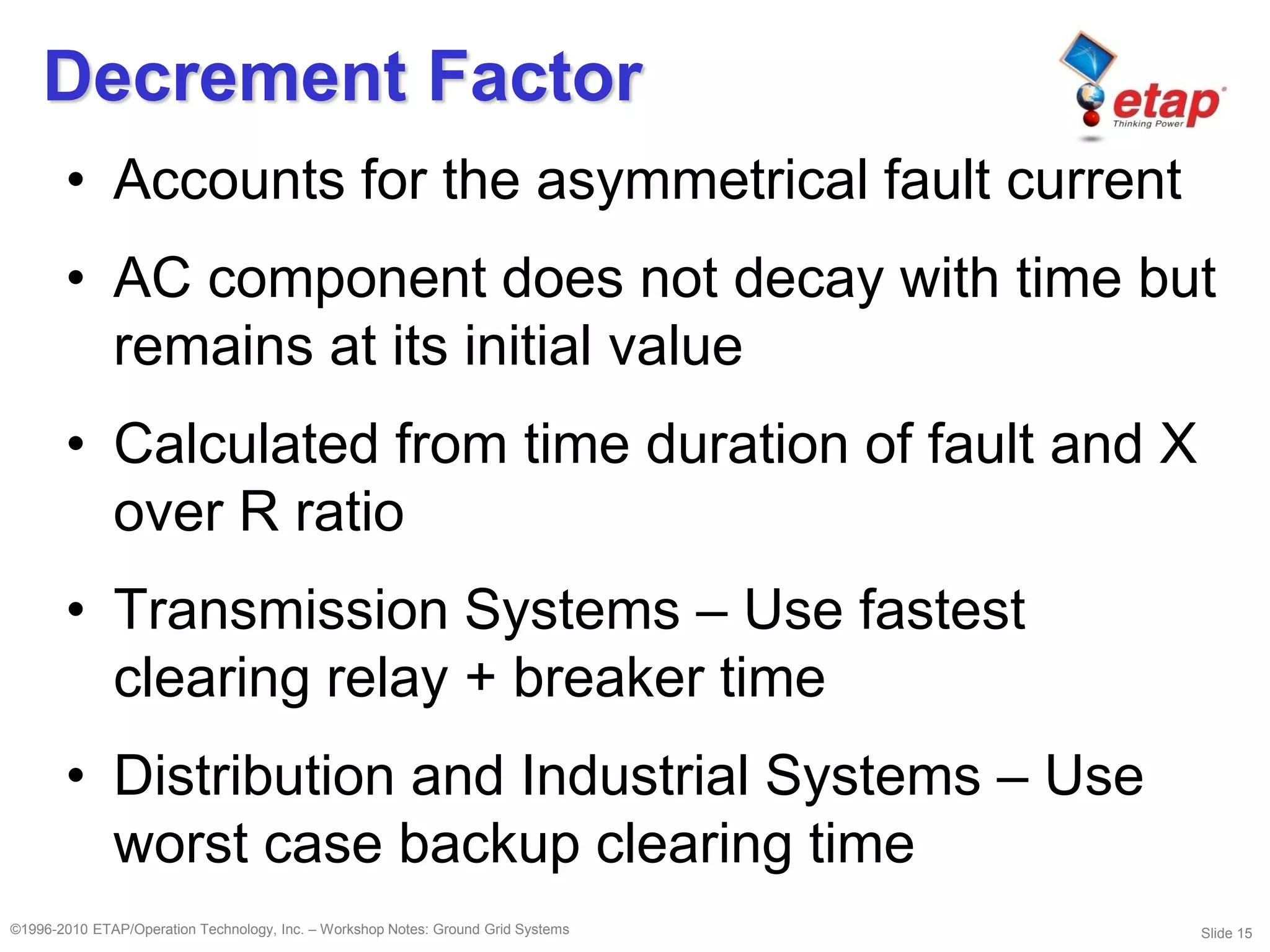
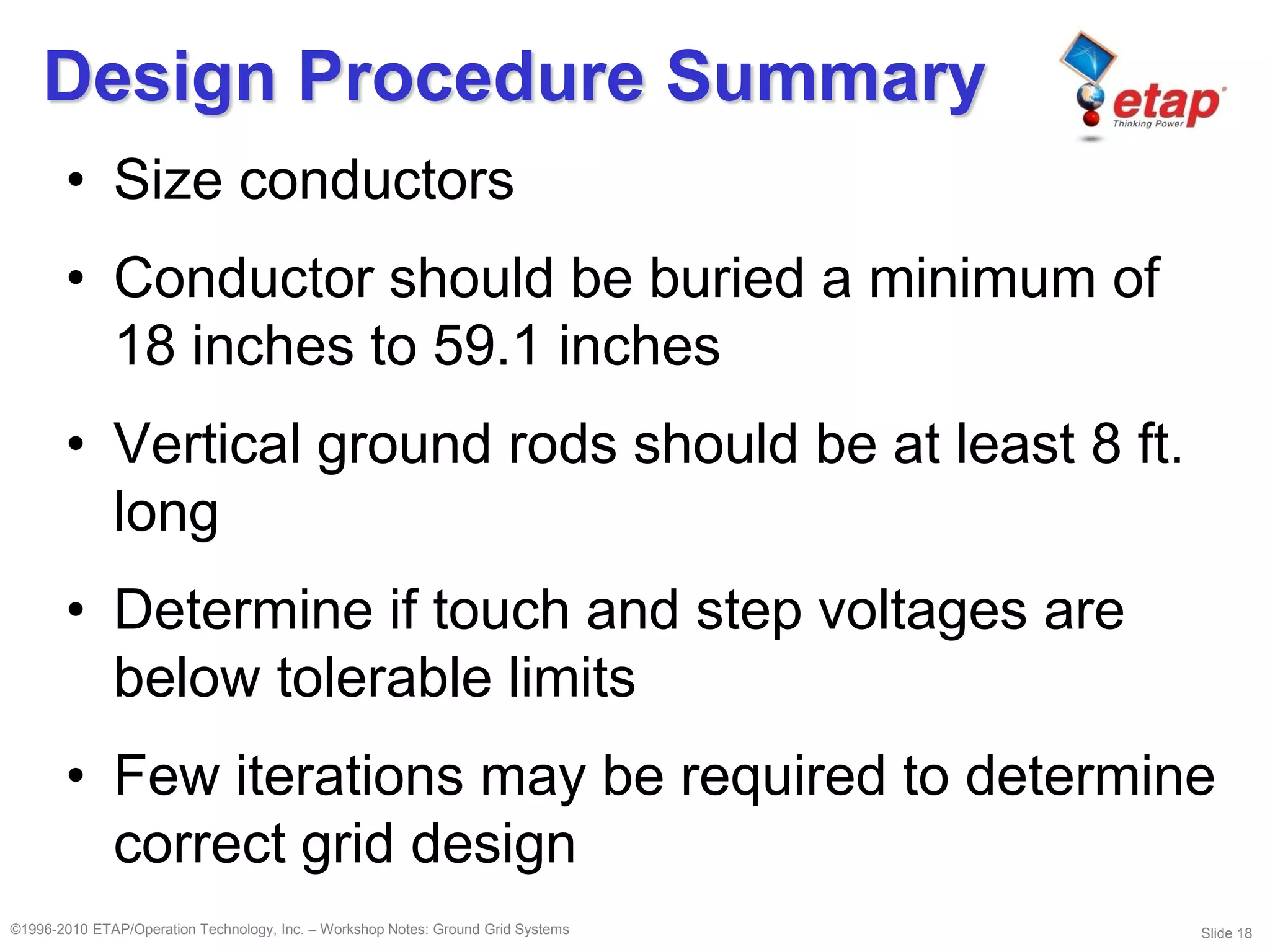
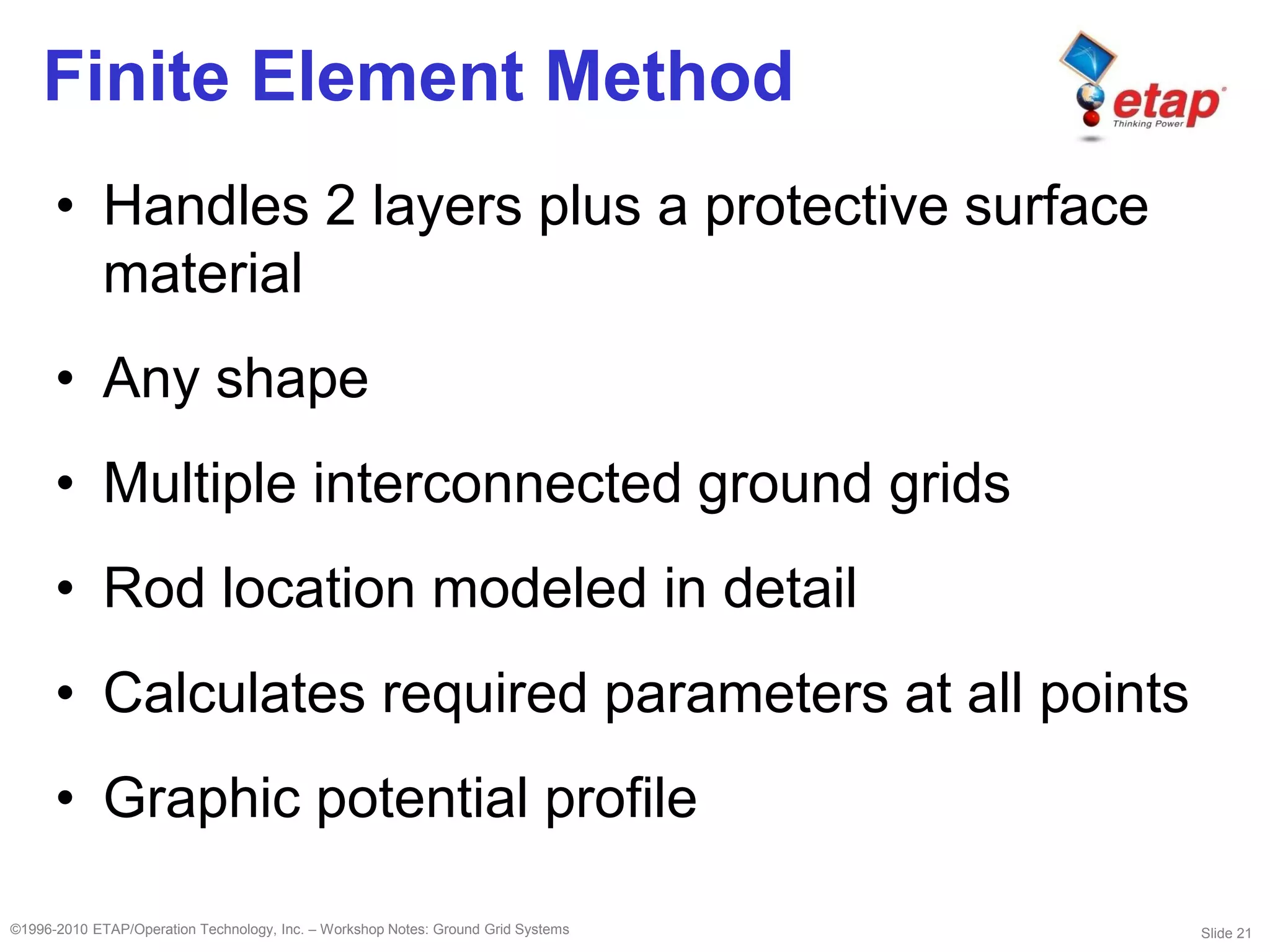
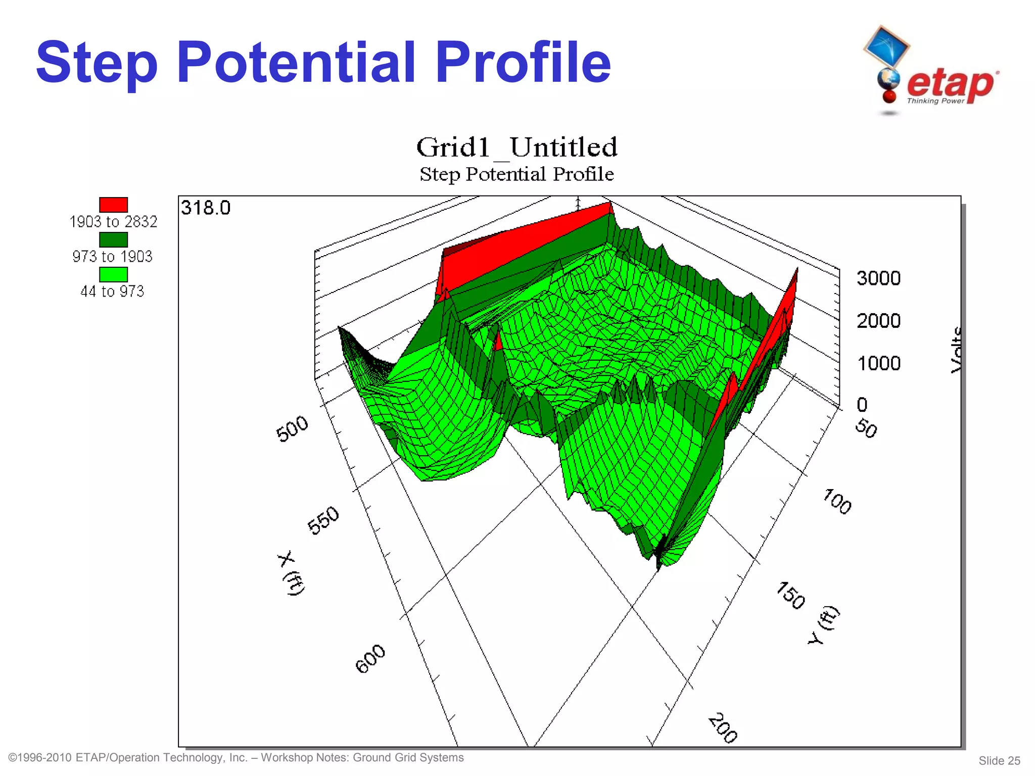
©1996-2010 ETAP/Operation Technology, Inc. – Workshop Notes: Ground Grid Systems
Ground Grid Systems
Slide 2©1996-2010 ETAP/Operation Technology, Inc. – Workshop Notes: Ground Grid Systems
Need for Grounding Grids
• Currents flow into the grounding grid from:
– Lightning Arrester Operations
– Switching Surge Flashover of Insulators
– Line-Ground Fault from Connected Bus
– Line-Ground Fault from Connected Line
Slide 3©1996-2010 ETAP/Operation Technology, Inc. – Workshop Notes: Ground Grid Systems
Objectives
• Human and animal safety
• Carry and dissipate current into earth under
normal and fault conditions
• Grounding for lightning impulses and surges
• Low resistance to ground for protective
relays
Slide 4©1996-2010 ETAP/Operation Technology, Inc. – Workshop Notes: Ground Grid Systems
Construction
Slide 5©1996-2010 ETAP/Operation Technology, Inc. – Workshop Notes: Ground Grid Systems
Common Definitions
• Earth Current
• Ground Fault Current
• Ground Potential Rise
• Step Voltage
• Touch Voltage
Slide 6©1996-2010 ETAP/Operation Technology, Inc. – Workshop Notes: Ground Grid Systems
Step 1 – Soil Analysis
• Done at a number of places in the substation
• Several layers with different resistivity
• Lateral surface changes are more gradual
than vertical changes
• Wenner Four-Pin Method
Slide 7©1996-2010 ETAP/Operation Technology, Inc. – Workshop Notes: Ground Grid Systems
Wenner Four-Pin Method
2222
4
2
1
4
ba
a
ba
a
aR
a
Slide 8©1996-2010 ETAP/Operation Technology, Inc. – Workshop Notes: Ground Grid Systems
Step 2 – Grid Area
• Area should be as large as possible
• Increasing area is more effective than
adding additional conductor to reduce grid
resistance
• Outer conductor should be placed on the
boundary of substation
• Fence should be placed a minimum of 3 feet
inside
• Square, rectangular, triangular, T-shaped, or
L-shaped grids
Slide 9©1996-2010 ETAP/Operation Technology, Inc. – Workshop Notes: Ground Grid Systems
Step 3 – Ground Fault
Currents
• L-G fault on substation bus or transmission
line
• Interested in maximum amount of fault
current expected to flow into the ground grid
• Determine maximum symmetrical rms fault
current
Slide 10©1996-2010 ETAP/Operation Technology, Inc. – Workshop Notes: Ground Grid Systems
Ground Fault Current
Slide 11©1996-2010 ETAP/Operation Technology, Inc. – Workshop Notes: Ground Grid Systems
Ground Fault Current
Slide 12©1996-2010 ETAP/Operation Technology, Inc. – Workshop Notes: Ground Grid Systems
Ground Fault Current
Slide 13©1996-2010 ETAP/Operation Technology, Inc. – Workshop Notes: Ground Grid Systems
Ground Fault Current
Slide 14©1996-2010 ETAP/Operation Technology, Inc. – Workshop Notes: Ground Grid Systems
Symmetrical Grid Current
• Io = Symmetrical rms value of Zero
Sequence fault current in amperes
• Transmission Systems – Model Maximum Io
for L-G fault for present and ultimate
configuration
• Distribution Systems – Model future fault
current with suitable growth factor (1.1)
)3(* ofg ISI
Slide 15©1996-2010 ETAP/Operation Technology, Inc. – Workshop Notes: Ground Grid Systems
Decrement Factor
• Accounts for the asymmetrical fault current
• AC component does not decay with time but
remains at its initial value
• Calculated from time duration of fault and X
over R ratio
• Transmission Systems – Use fastest
clearing relay + breaker time
• Distribution and Industrial Systems – Use
worst case backup clearing time
Slide 16©1996-2010 ETAP/Operation Technology, Inc. – Workshop Notes: Ground Grid Systems
Typical Shock Situations
Slide 17©1996-2010 ETAP/Operation Technology, Inc. – Workshop Notes: Ground Grid Systems
Design Procedure Summary
• Use network of bare conductors buried in the
earth
• Encompass all area within the substation
fence and extend at least 3 feet outside
• Perform soil resistivity test
• Surface material at least 4 inches
• Determine fault current using short circuit
• Determine maximum clearing time
Slide 18©1996-2010 ETAP/Operation Technology, Inc. – Workshop Notes: Ground Grid Systems
Design Procedure Summary
• Size conductors
• Conductor should be buried a minimum of
18 inches to 59.1 inches
• Vertical ground rods should be at least 8 ft.
long
• Determine if touch and step voltages are
below tolerable limits
• Few iterations may be required to determine
correct grid design
Slide 19©1996-2010 ETAP/Operation Technology, Inc. – Workshop Notes: Ground Grid Systems
Ground Rod Length
• Three schools of thought
– Length of 10ft is adequate
– Length of 40ft is required to reach water table
– Longest possible rod depth should be used
Slide 20©1996-2010 ETAP/Operation Technology, Inc. – Workshop Notes: Ground Grid Systems
IEEE Methods
• Empirical method; limited applications
• Handles 2 layers plus protective surface
material (1 layer for touch potential)
• Rectangular and triangular shapes only, with
vertical and horizontal conductors
• One ground grid only
• Rods; but arrangements are not flexible
• Calculates required parameters
Slide 21©1996-2010 ETAP/Operation Technology, Inc. – Workshop Notes: Ground Grid Systems
Finite Element Method
• Handles 2 layers plus a protective surface
material
• Any shape
• Multiple interconnected ground grids
• Rod location modeled in detail
• Calculates required parameters at all points
• Graphic potential profile
Slide 22©1996-2010 ETAP/Operation Technology, Inc. – Workshop Notes: Ground Grid Systems
Typical IEEE Grid
Slide 23©1996-2010 ETAP/Operation Technology, Inc. – Workshop Notes: Ground Grid Systems
IEEE Grid Description
• 40 ft. X 40 ft. square grid with 8 conductors
along X-axis and 8 conductors along Y-axis
• Depth = 1.5 ft., 4/0 copper-clad steel wire
• 1 rod in each grid corner, diameter = 0.5 in.,
length = 8 ft. same material as conductor
Slide 24©1996-2010 ETAP/Operation Technology, Inc. – Workshop Notes: Ground Grid Systems
FEM Grid Example
Slide 25©1996-2010 ETAP/Operation Technology, Inc. – Workshop Notes: Ground Grid Systems
Step Potential Profile
Slide 26©1996-2010 ETAP/Operation Technology, Inc. – Workshop Notes: Ground Grid Systems
Touch Potential Profile
Slide 27©1996-2010 ETAP/Operation Technology, Inc. – Workshop Notes: Ground Grid Systems
Absolute Potential Profile

ETAP - Ground grid systems

  • 1.
    ©1996-2010 ETAP/Operation Technology,Inc. – Workshop Notes: Ground Grid Systems Ground Grid Systems
  • 2.
    Slide 2©1996-2010 ETAP/OperationTechnology, Inc. – Workshop Notes: Ground Grid Systems Need for Grounding Grids • Currents flow into the grounding grid from: – Lightning Arrester Operations – Switching Surge Flashover of Insulators – Line-Ground Fault from Connected Bus – Line-Ground Fault from Connected Line
  • 3.
    Slide 3©1996-2010 ETAP/OperationTechnology, Inc. – Workshop Notes: Ground Grid Systems Objectives • Human and animal safety • Carry and dissipate current into earth under normal and fault conditions • Grounding for lightning impulses and surges • Low resistance to ground for protective relays
  • 4.
    Slide 4©1996-2010 ETAP/OperationTechnology, Inc. – Workshop Notes: Ground Grid Systems Construction
  • 5.
    Slide 5©1996-2010 ETAP/OperationTechnology, Inc. – Workshop Notes: Ground Grid Systems Common Definitions • Earth Current • Ground Fault Current • Ground Potential Rise • Step Voltage • Touch Voltage
  • 6.
    Slide 6©1996-2010 ETAP/OperationTechnology, Inc. – Workshop Notes: Ground Grid Systems Step 1 – Soil Analysis • Done at a number of places in the substation • Several layers with different resistivity • Lateral surface changes are more gradual than vertical changes • Wenner Four-Pin Method
  • 7.
    Slide 7©1996-2010 ETAP/OperationTechnology, Inc. – Workshop Notes: Ground Grid Systems Wenner Four-Pin Method 2222 4 2 1 4 ba a ba a aR a
  • 8.
    Slide 8©1996-2010 ETAP/OperationTechnology, Inc. – Workshop Notes: Ground Grid Systems Step 2 – Grid Area • Area should be as large as possible • Increasing area is more effective than adding additional conductor to reduce grid resistance • Outer conductor should be placed on the boundary of substation • Fence should be placed a minimum of 3 feet inside • Square, rectangular, triangular, T-shaped, or L-shaped grids
  • 9.
    Slide 9©1996-2010 ETAP/OperationTechnology, Inc. – Workshop Notes: Ground Grid Systems Step 3 – Ground Fault Currents • L-G fault on substation bus or transmission line • Interested in maximum amount of fault current expected to flow into the ground grid • Determine maximum symmetrical rms fault current
  • 10.
    Slide 10©1996-2010 ETAP/OperationTechnology, Inc. – Workshop Notes: Ground Grid Systems Ground Fault Current
  • 11.
    Slide 11©1996-2010 ETAP/OperationTechnology, Inc. – Workshop Notes: Ground Grid Systems Ground Fault Current
  • 12.
    Slide 12©1996-2010 ETAP/OperationTechnology, Inc. – Workshop Notes: Ground Grid Systems Ground Fault Current
  • 13.
    Slide 13©1996-2010 ETAP/OperationTechnology, Inc. – Workshop Notes: Ground Grid Systems Ground Fault Current
  • 14.
    Slide 14©1996-2010 ETAP/OperationTechnology, Inc. – Workshop Notes: Ground Grid Systems Symmetrical Grid Current • Io = Symmetrical rms value of Zero Sequence fault current in amperes • Transmission Systems – Model Maximum Io for L-G fault for present and ultimate configuration • Distribution Systems – Model future fault current with suitable growth factor (1.1) )3(* ofg ISI
  • 15.
    Slide 15©1996-2010 ETAP/OperationTechnology, Inc. – Workshop Notes: Ground Grid Systems Decrement Factor • Accounts for the asymmetrical fault current • AC component does not decay with time but remains at its initial value • Calculated from time duration of fault and X over R ratio • Transmission Systems – Use fastest clearing relay + breaker time • Distribution and Industrial Systems – Use worst case backup clearing time
  • 16.
    Slide 16©1996-2010 ETAP/OperationTechnology, Inc. – Workshop Notes: Ground Grid Systems Typical Shock Situations
  • 17.
    Slide 17©1996-2010 ETAP/OperationTechnology, Inc. – Workshop Notes: Ground Grid Systems Design Procedure Summary • Use network of bare conductors buried in the earth • Encompass all area within the substation fence and extend at least 3 feet outside • Perform soil resistivity test • Surface material at least 4 inches • Determine fault current using short circuit • Determine maximum clearing time
  • 18.
    Slide 18©1996-2010 ETAP/OperationTechnology, Inc. – Workshop Notes: Ground Grid Systems Design Procedure Summary • Size conductors • Conductor should be buried a minimum of 18 inches to 59.1 inches • Vertical ground rods should be at least 8 ft. long • Determine if touch and step voltages are below tolerable limits • Few iterations may be required to determine correct grid design
  • 19.
    Slide 19©1996-2010 ETAP/OperationTechnology, Inc. – Workshop Notes: Ground Grid Systems Ground Rod Length • Three schools of thought – Length of 10ft is adequate – Length of 40ft is required to reach water table – Longest possible rod depth should be used
  • 20.
    Slide 20©1996-2010 ETAP/OperationTechnology, Inc. – Workshop Notes: Ground Grid Systems IEEE Methods • Empirical method; limited applications • Handles 2 layers plus protective surface material (1 layer for touch potential) • Rectangular and triangular shapes only, with vertical and horizontal conductors • One ground grid only • Rods; but arrangements are not flexible • Calculates required parameters
  • 21.
    Slide 21©1996-2010 ETAP/OperationTechnology, Inc. – Workshop Notes: Ground Grid Systems Finite Element Method • Handles 2 layers plus a protective surface material • Any shape • Multiple interconnected ground grids • Rod location modeled in detail • Calculates required parameters at all points • Graphic potential profile
  • 22.
    Slide 22©1996-2010 ETAP/OperationTechnology, Inc. – Workshop Notes: Ground Grid Systems Typical IEEE Grid
  • 23.
    Slide 23©1996-2010 ETAP/OperationTechnology, Inc. – Workshop Notes: Ground Grid Systems IEEE Grid Description • 40 ft. X 40 ft. square grid with 8 conductors along X-axis and 8 conductors along Y-axis • Depth = 1.5 ft., 4/0 copper-clad steel wire • 1 rod in each grid corner, diameter = 0.5 in., length = 8 ft. same material as conductor
  • 24.
    Slide 24©1996-2010 ETAP/OperationTechnology, Inc. – Workshop Notes: Ground Grid Systems FEM Grid Example
  • 25.
    Slide 25©1996-2010 ETAP/OperationTechnology, Inc. – Workshop Notes: Ground Grid Systems Step Potential Profile
  • 26.
    Slide 26©1996-2010 ETAP/OperationTechnology, Inc. – Workshop Notes: Ground Grid Systems Touch Potential Profile
  • 27.
    Slide 27©1996-2010 ETAP/OperationTechnology, Inc. – Workshop Notes: Ground Grid Systems Absolute Potential Profile