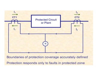
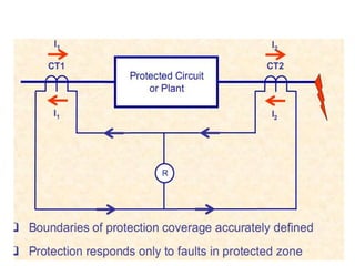
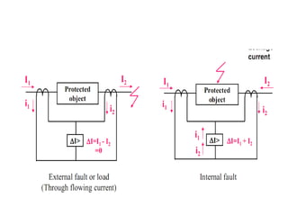
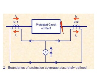
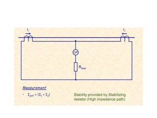
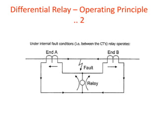
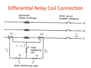
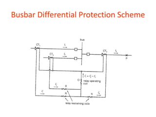
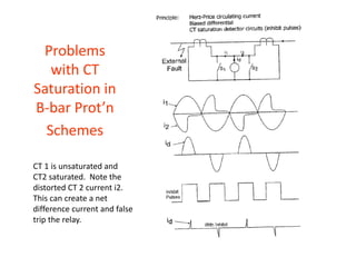
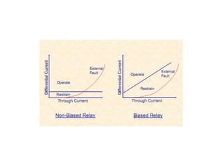
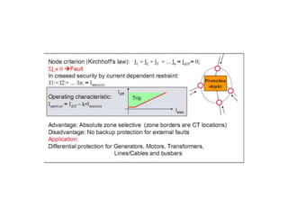
1) Differential protection compares currents flowing into and out of a protected zone. A difference indicates an internal fault. Modern relays use microprocessors to compare currents.
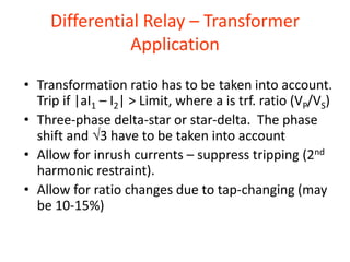
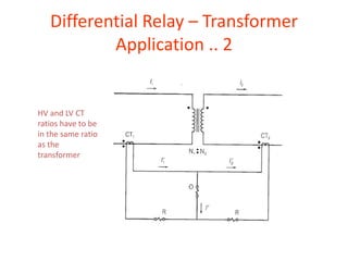
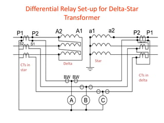
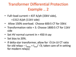
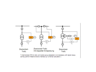
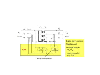
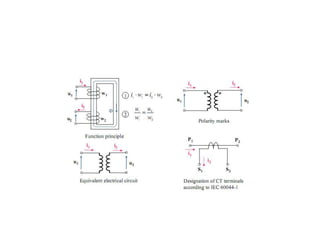
2) Differential protection is applied to transformers by taking the transformation ratio into account. Ratios of current transformers (CTs) on the high voltage and low voltage sides must match the transformer ratio.
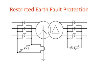
3) Restricted earth fault protection monitors residual current to protect transformer windings against earth faults, providing coverage where overcurrent protection is insufficient.