Downloaded 143 times


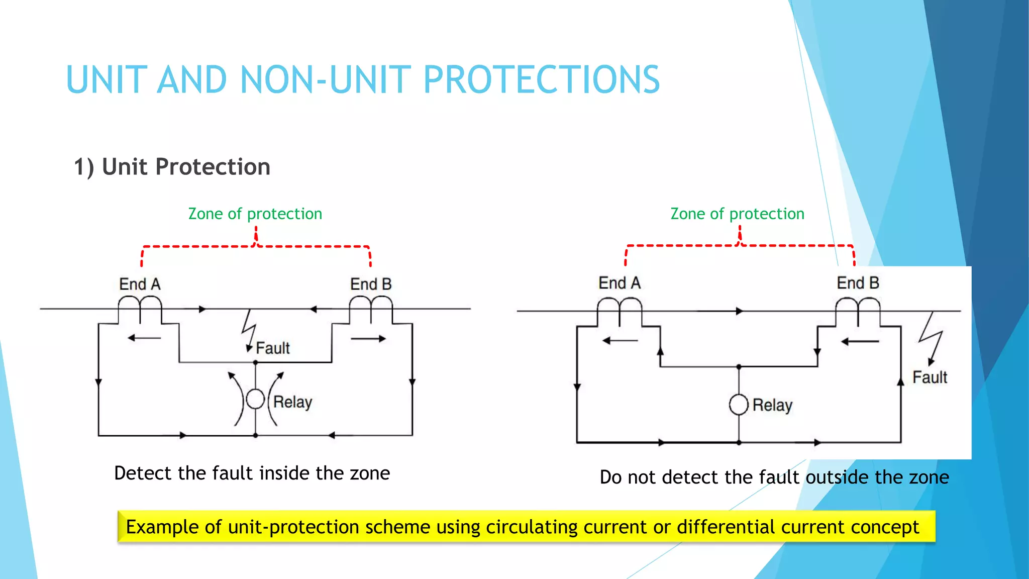
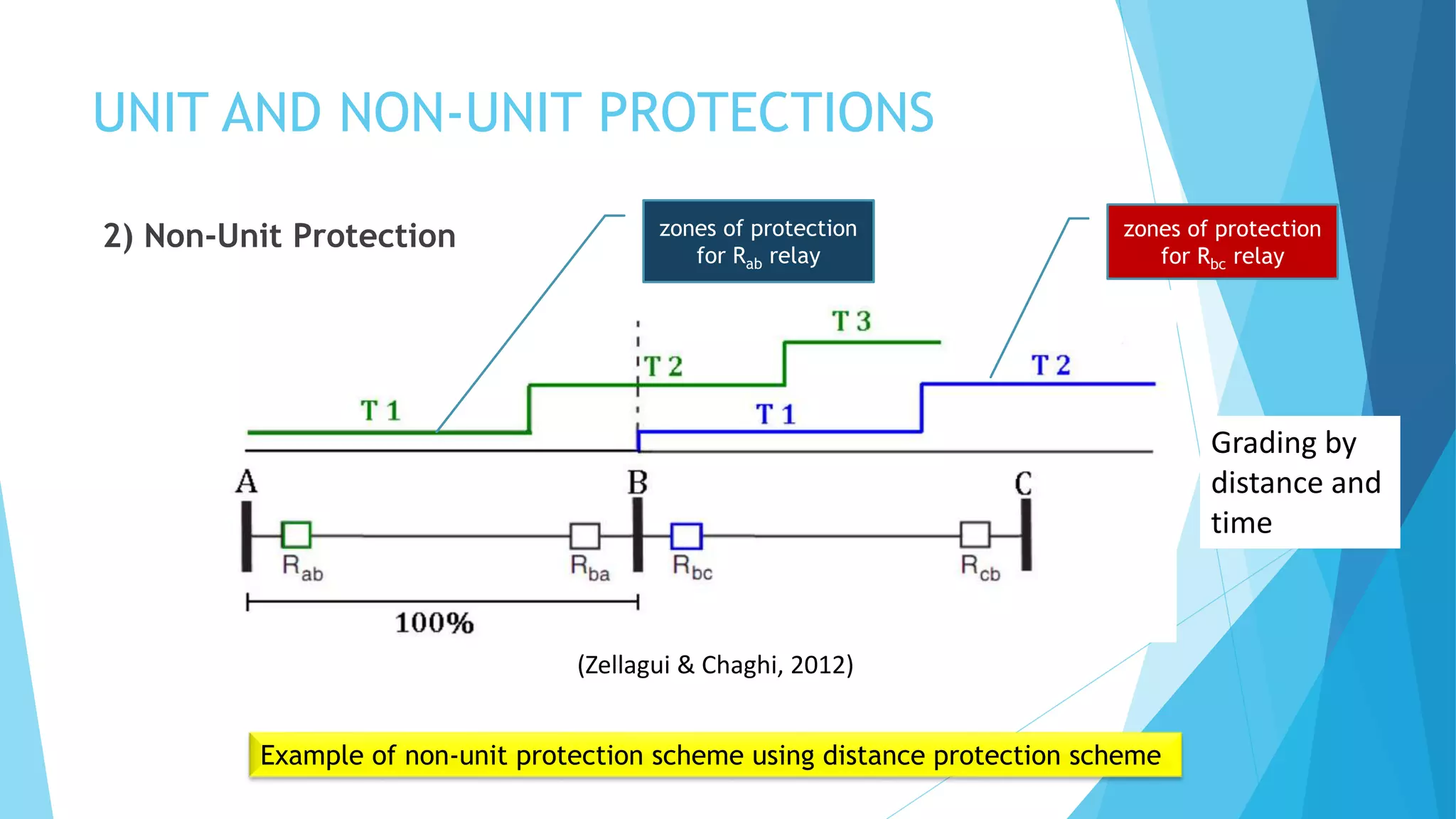


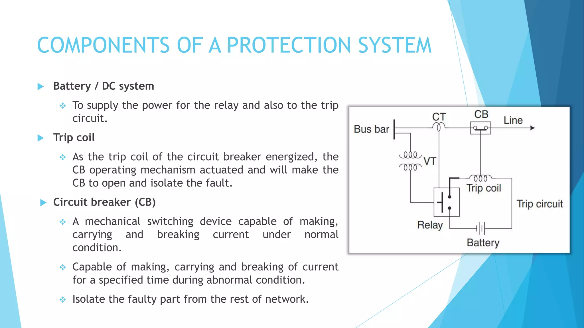
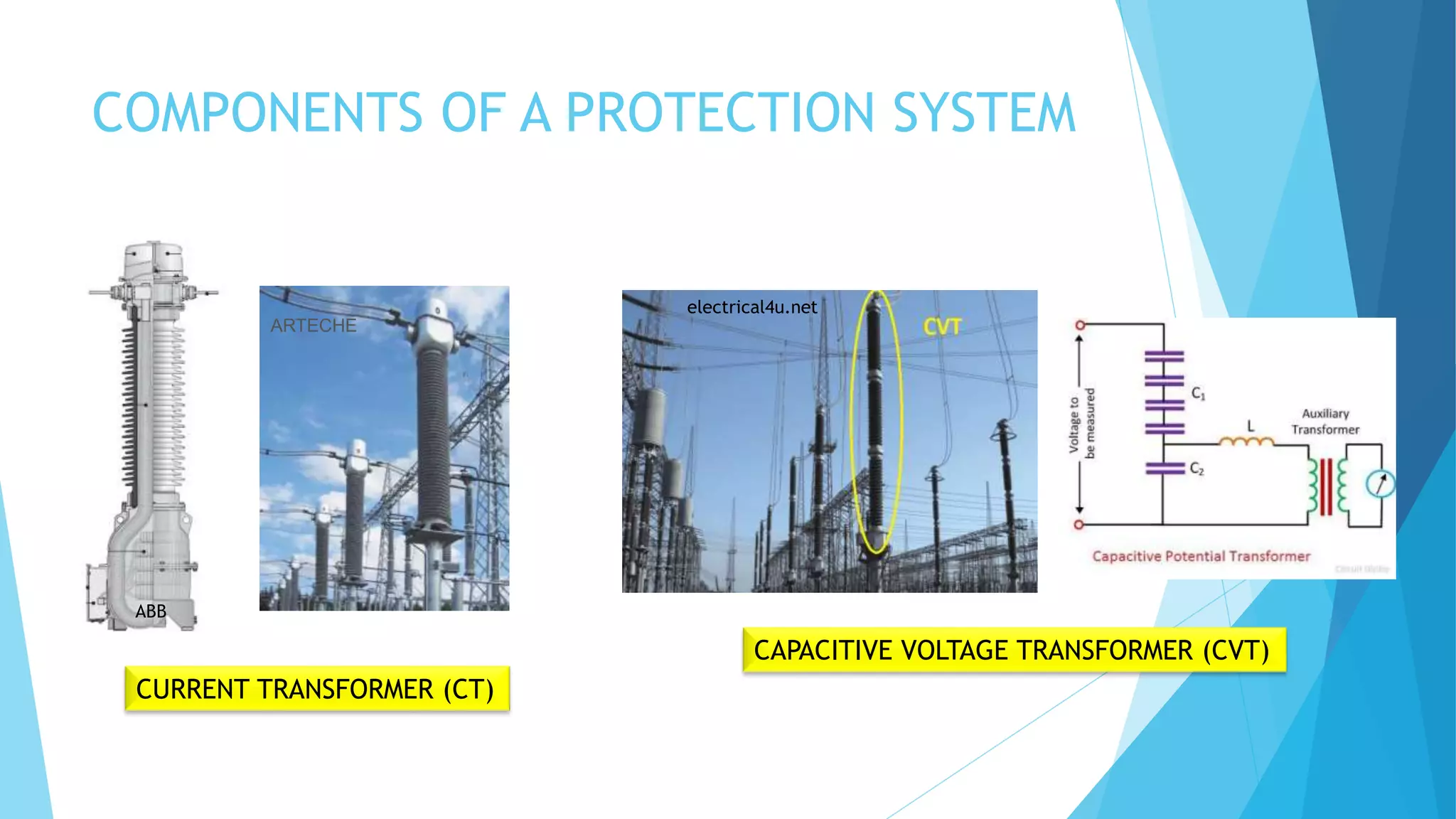

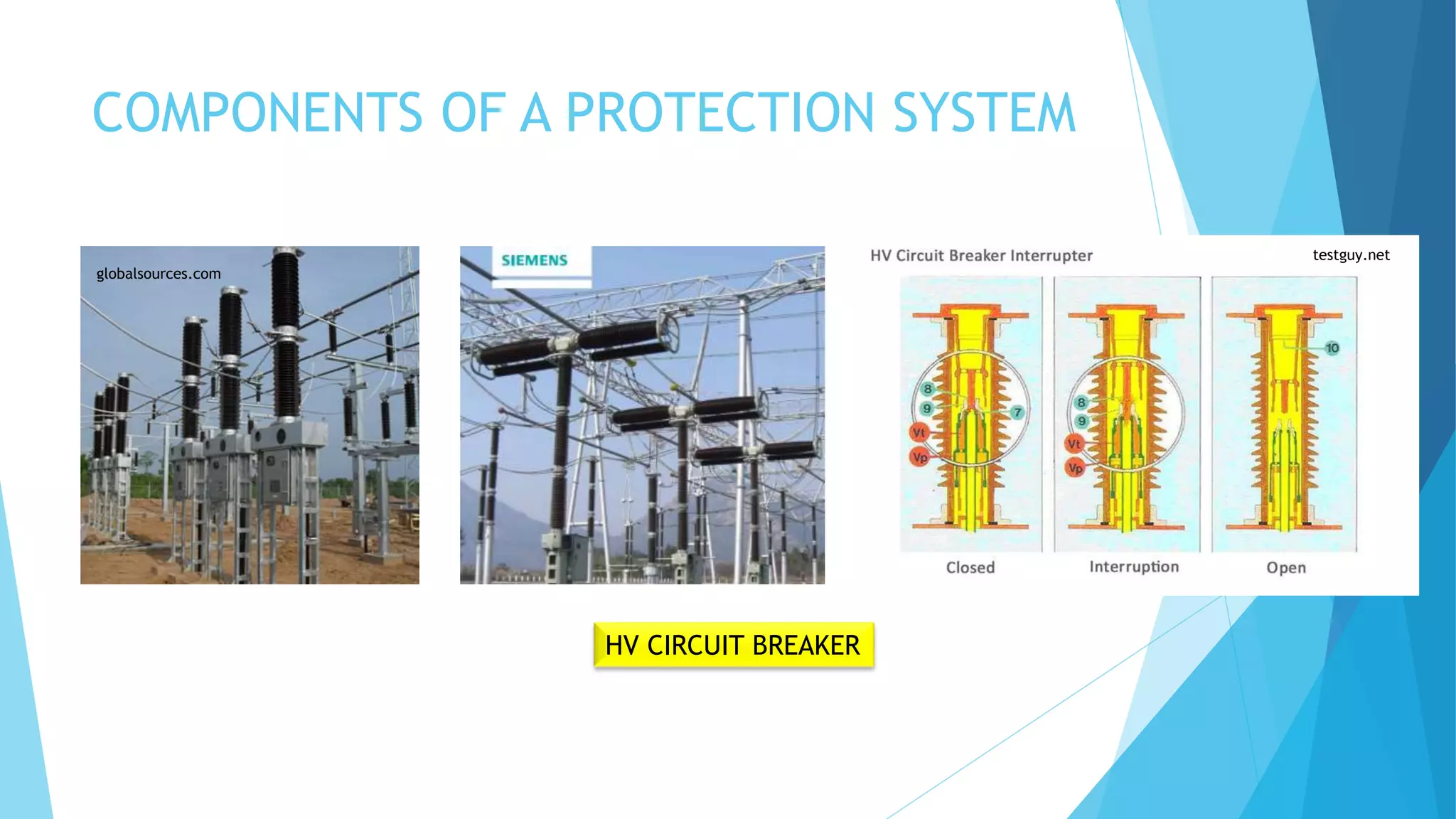

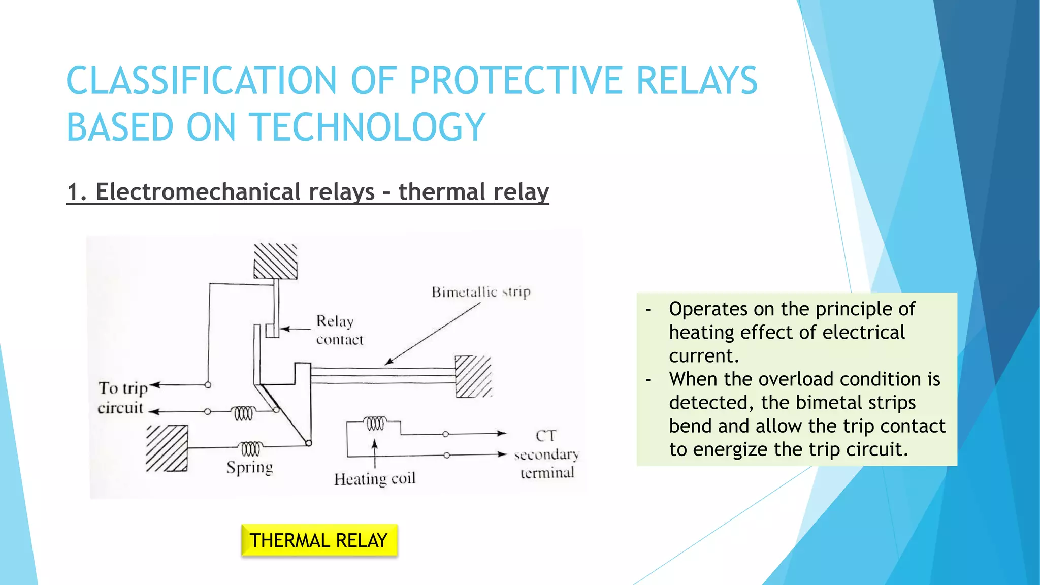
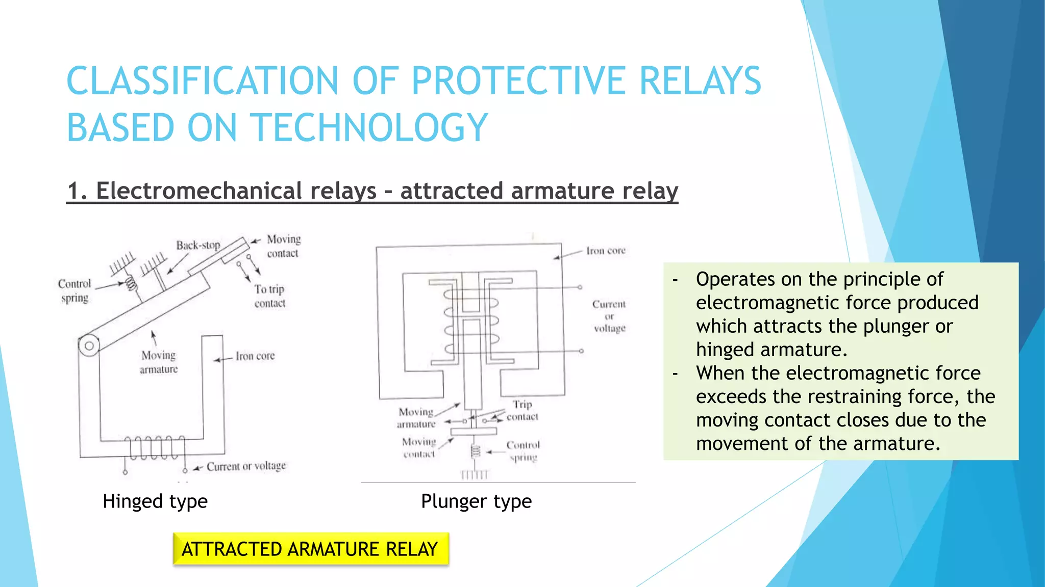

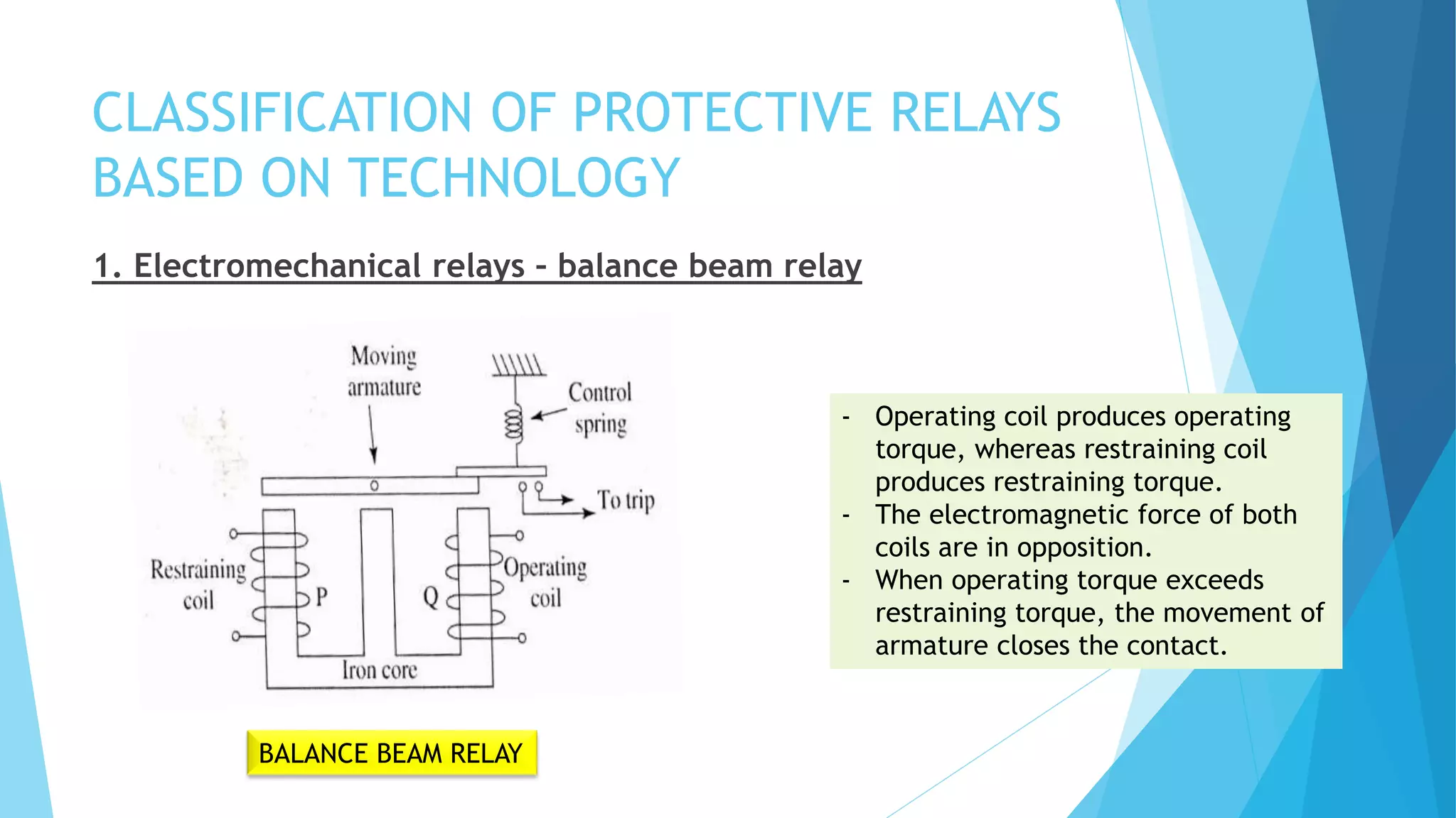
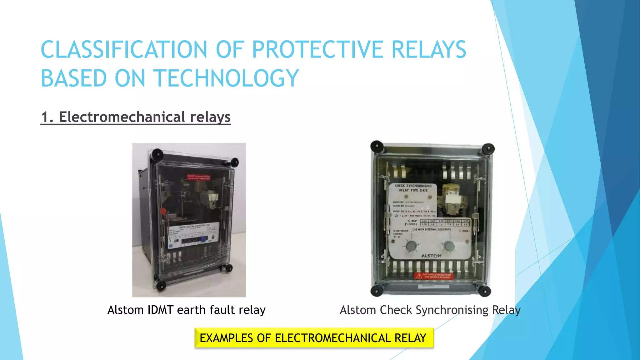
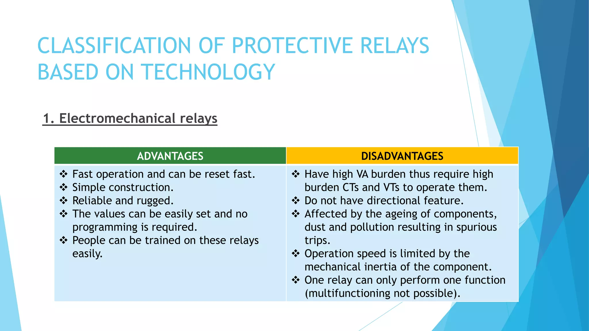


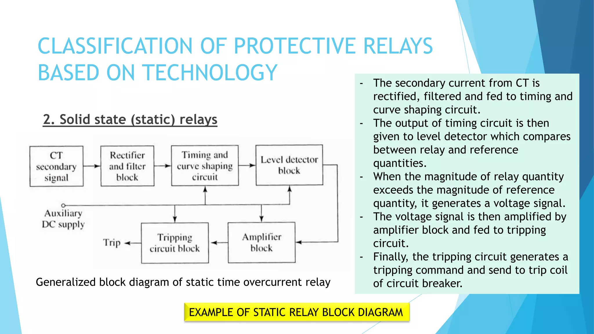


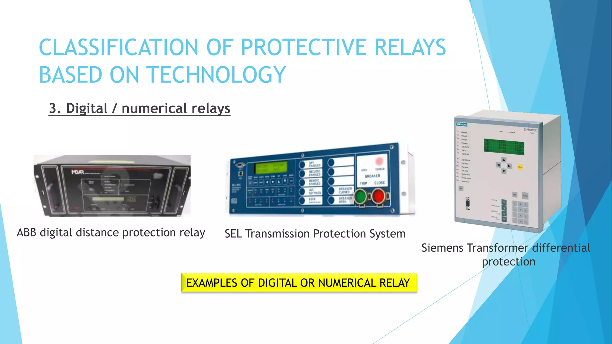


The document provides a comprehensive overview of protective relaying in power systems, detailing the functions, requirements, and types of protection schemes including unit and non-unit protections. It discusses various components of protection systems, different types of protective relays based on technology (electromechanical, solid state, and digital), and their respective advantages and disadvantages. Additionally, the document covers the ANSI standard device numbers used to identify protective devices in schematic diagrams.


