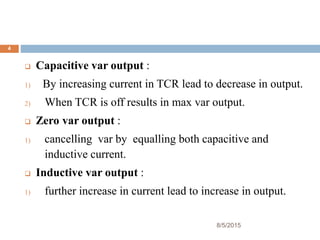
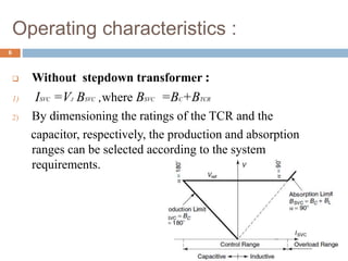
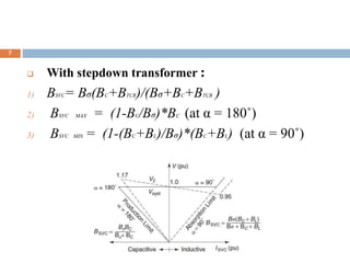
FC-TCR
Prepared By :
Upadhyay Rakshita R .
Er No : 140370707018
Roll no : 24
Contents…
8/5/2015
2
 Introduction
 Circuit diagram
 Operating characteristics
 Losses in FC-TCR
 Conclusion
 References
Introduction
8/5/2015
3
 Objective : To maintain the desired voltage at a high
voltage bus.
 FC-TCR is a var generator arrangement using a
Fixed capacitance with a TCR.
 The current in the reactor is varied by the method of
firing delay angle control method. (Qc) of the fixed
capacitor is opposed by the (QL) of the TCR.
8/5/2015
4
 Capacitive var output :
1) By increasing current in TCR lead to decrease in output.
2) When TCR is off results in max var output.
 Zero var output :
1) cancelling var by equalling both capacitive and
inductive current.
 Inductive var output :
1) further increase in current lead to increase in output.
Circuit diagram:
8/5/2015
5
 Components :
1) A TCR
2) A fix capacitor across TCR
3) High pass filter
Operating characteristics :
8/5/2015
6
 Without stepdown transformer :
1) ISVC =VJ BSVC ,where BSVC =BC+BTCR
2) By dimensioning the ratings of the TCR and the
capacitor, respectively, the production and absorption
ranges can be selected according to the system
requirements.
8/5/2015
7
 With stepdown transformer :
1) BSVC= Bσ(BC+BTCR)/(Bσ+BC+BTCR )
2) BSVC MAX = (1-BC/Bσ)*BC (at α = 180˚)
3) BSVC MIN = (1-(BC+BL)/Bσ)*(BC+BL) (at α = 90˚)
Losses in FC-TCR
8/5/2015
8
 Circulation of large current for cancelling capacitive var
resulting high steady state losses.
 Losses can be minimized by switching the fixed
capacitors through mechanical breakers, ensuring that the
capacitors are inserted in the compensator circuit only
when leading vars are needed.
Conclusion
8/5/2015
9
 FC-TCR is useful for getting controllable range of var
output with a capacitor connected across TCR. And
losses can be minimized by switching the fixed capacitor
by mechanical breakers.
References
8/5/2015
10
 ‘Thyristor-based FACTS controllers for Electrical
Transmission Systems,’ R. Mohan Mathur, R K Verma,
Wiley IEEE Press
 ‘Reactive power control using FC-TCR’,Ms shilpa gupta,
IJITR,volume-1,january-2013,india
8/5/2015
11

Fc tcr.newpptx

  • 1.
    FC-TCR Prepared By : UpadhyayRakshita R . Er No : 140370707018 Roll no : 24
  • 2.
    Contents… 8/5/2015 2  Introduction  Circuitdiagram  Operating characteristics  Losses in FC-TCR  Conclusion  References
  • 3.
    Introduction 8/5/2015 3  Objective :To maintain the desired voltage at a high voltage bus.  FC-TCR is a var generator arrangement using a Fixed capacitance with a TCR.  The current in the reactor is varied by the method of firing delay angle control method. (Qc) of the fixed capacitor is opposed by the (QL) of the TCR.
  • 4.
    8/5/2015 4  Capacitive varoutput : 1) By increasing current in TCR lead to decrease in output. 2) When TCR is off results in max var output.  Zero var output : 1) cancelling var by equalling both capacitive and inductive current.  Inductive var output : 1) further increase in current lead to increase in output.
  • 5.
    Circuit diagram: 8/5/2015 5  Components: 1) A TCR 2) A fix capacitor across TCR 3) High pass filter
  • 6.
    Operating characteristics : 8/5/2015 6 Without stepdown transformer : 1) ISVC =VJ BSVC ,where BSVC =BC+BTCR 2) By dimensioning the ratings of the TCR and the capacitor, respectively, the production and absorption ranges can be selected according to the system requirements.
  • 7.
    8/5/2015 7  With stepdowntransformer : 1) BSVC= Bσ(BC+BTCR)/(Bσ+BC+BTCR ) 2) BSVC MAX = (1-BC/Bσ)*BC (at α = 180˚) 3) BSVC MIN = (1-(BC+BL)/Bσ)*(BC+BL) (at α = 90˚)
  • 8.
    Losses in FC-TCR 8/5/2015 8 Circulation of large current for cancelling capacitive var resulting high steady state losses.  Losses can be minimized by switching the fixed capacitors through mechanical breakers, ensuring that the capacitors are inserted in the compensator circuit only when leading vars are needed.
  • 9.
    Conclusion 8/5/2015 9  FC-TCR isuseful for getting controllable range of var output with a capacitor connected across TCR. And losses can be minimized by switching the fixed capacitor by mechanical breakers.
  • 10.
    References 8/5/2015 10  ‘Thyristor-based FACTScontrollers for Electrical Transmission Systems,’ R. Mohan Mathur, R K Verma, Wiley IEEE Press  ‘Reactive power control using FC-TCR’,Ms shilpa gupta, IJITR,volume-1,january-2013,india
  • 11.