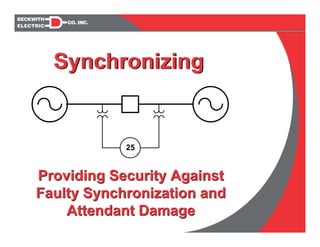
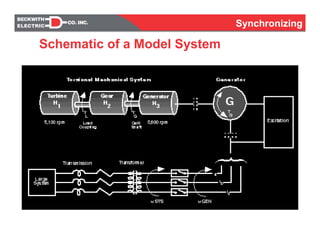
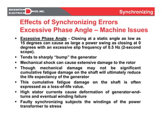
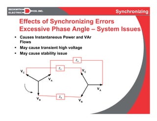
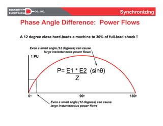
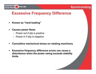
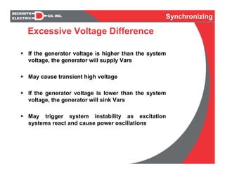
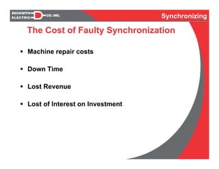
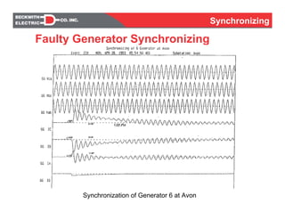
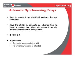
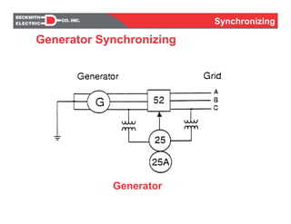
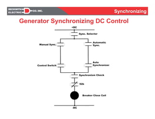
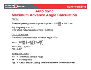
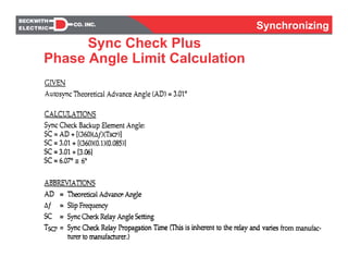
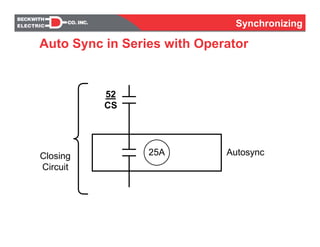
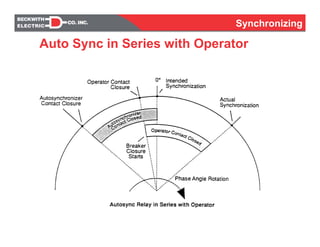
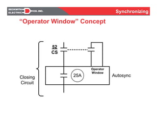
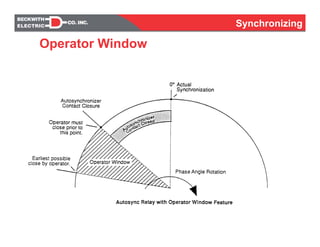
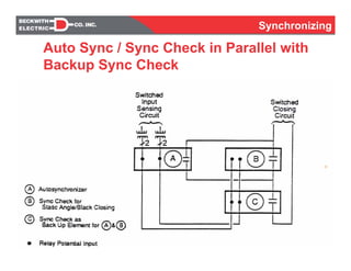
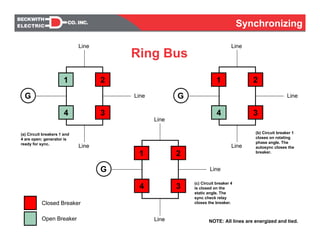
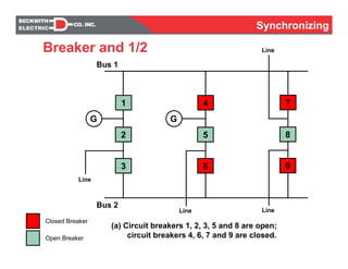
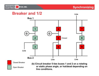
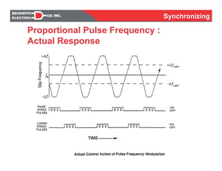
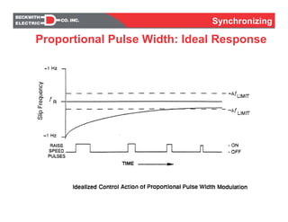
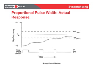
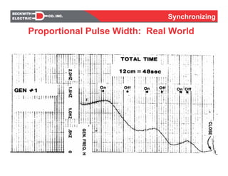
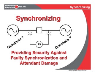
Providing Security Against
Faulty Synchronization and
Attendant Damage
Providing Security Against
Faulty Synchronization and
Attendant Damage
25
SynchronizingSynchronizing
Synchronizing
As protection practitioners, we spend the majority
of our time designing protection systems to trip
Designing a protection system to close requires
careful attention to security
You want to provide security against improper
closure of two electrical sources
What defines proper closure?
Introduction
Synchronizing
Synchronizing
Protect against harmful effects of closing two ac
electrical sources with excessive:
- Phase Angle Difference (Ø)
- Slip Frequency (ΔF or S)
- High or Low Voltage (UVL, LVL)
- Voltage Difference (ΔV)
Synchronizing is Used in Generator Synchronizing
and System Line Restoration Applications
Synchronizing
Introduction
SynchronizingSynchronizing
Φ
ΔV
f1
f2
Phase Angle
in 1cycle
Asynchronous Sine Waves
Synchronizing
Phasor Representation
Synchronizing
VA
VBVC
VA
Phase Difference 0º
P =
E1 E2---------------------------------------------------------------
Z
sin 0º
SynchronizingSynchronizing
Phase Difference 80º
VA
VBVC
VA
P =
E1 E2---------------------------------------------------------------
Z
sin 80º
Phasor Representation
SynchronizingSynchronizing
Phase Difference 160º
VA
VBVC
VA
P =
E1 E2---------------------------------------------------------------
Z
sin 160º
Phasor Representation
SynchronizingSynchronizing
Synchroscope
Display of
Phase Angle
Synchronizing
Schematic of a Model System
Synchronizing
Synchronizing
Effects of Synchronizing Errors
Excessive Phase Angle – Machine Issues
Excessive Phase Angle - Closing at a static angle as low as
15 degrees can cause as large a power swing as closing at 0
degrees with an excessive slip frequency of 0.5 Hz (2-second
scope).
Tends to sharply “bump” the generator
Mechanical shock can cause extensive damage to the rotor
Though mechanical damage may not be significant
cumulative fatigue damage on the shaft will ultimately reduce
the life expectancy of the generator
This cumulative fatigue damage on the shaft is often
expressed as a loss-of-life value.
High stator currents cause deformation of generator-end-
turns and eventual winding failure
Faulty synchronizing subjects the windings of the power
transformer to stress
Synchronizing
Synchronizing
Effects of Synchronizing Errors
Excessive Phase Angle – System Issues
Causes Instantaneous Power and VAr
Flows
May cause transient high voltage
May cause stability issue
Synchronizing
VA
VA
VB VB
VC
VC
ZB
ZA
ZC
Synchronizing
90O 180O0O
1 PU
Even a small angle (12 degrees) can cause
large instantaneous power flows
P= E1 * E2 (sin0)
Z
Even a small angle (12 degrees) can cause
large instantaneous power flows
Phase Angle Difference: Power Flows
A 12 degree close hard-loads a machine to 30% of full-load shock !
Synchronizing
Excessive Frequency Difference
Known as “hard loading”
Causes power flows
- Power out if slip is positive
- Power in if slip is negative
Cumulative mechanical stress on rotating machinery
Excessive frequency difference errors can cause a
disturbance when the power swing exceeds stability
limits
Synchronizing
Synchronizing
Excessive Voltage Difference
If the generator voltage is higher than the system
voltage, the generator will supply Vars
May cause transient high voltage
If the generator voltage is lower than the system
voltage, the generator will sink Vars
May trigger system instability as excitation
systems react and cause power oscillations
Synchronizing
Synchronizing
The Cost of Faulty Synchronization
Machine repair costs
Down Time
Lost Revenue
Lost of Interest on Investment
Synchronizing
Synchronizing
Faulty Generator Synchronizing
Synchronization of Generator 5-AT
Synchronizing
Faulty Generator Synchronizing
Synchronization of Generator 6 at Avon
SynchronizingSynchronizing
[1] Robert W. Beckwith, "Calculations of Circuit Breaker Closing Criteria for
Synchronizing a Generator." Beckwith Electric Company, August 1979.
[2] I. M. Canay, H. J. Rohrer, K. E. Schnirel, "Effect of Electrical Disturbances,
Grid Recovery Voltage and Generator Inertia on Maximization of Mechanical
Torques in Large Turbogenerator Sets." IEEE Transactions on Power
Apparatus and Systems, Vol. PAS-99, No.4, July/August 1980, pp. 1357-1370.
[3] H. H. Chen, G. E. Jablonka, J. V. Mitsche, J.B. Lewis, "Turbine-Generator
Loss-of-Life Analysis Following a Faulty Synchronization Incident." American
Power Conference, Chicago, Illinois, April 21-23, 1980.
[4] R. D. Dunlop, A. C. Parikn, "Verification of Synchronous Machine Modeling
in Stability Studies: Comparative Tests of Digital and physical Scale Model
Power System Simulations. IEEE Transactions on Power Apparatus and
Systems, Vol. PAS -98, No.2, March/April 1979, pp. 369-378.
[5] D. R. Green, et al, "IEEE Screening Guide for Planned Steady-State
Switching Operations to Minimize Harmful Effects on Steam Turbine-
Generators." IEEE Transactions on Power Apparatus and Systems, Vol. PAS-
99, No.4, July/August 1980, pp. 1519-1521.
References
SynchronizingSynchronizing
[6] T. J. Hammons, "Stressing of Large Turbine-Generators at Shaft Couplings
and LP Turbine Final-Stage Blade Roots Following Clearance of Grid System
Faults and Faulty Synchronization." IEEE Transactions on Power Apparatus and
Systems, Vol. PAS -99, No.4, July/ August 1980, pp. 1652-1662.
[7] M. C. Jackson, S. D. Umans, "Turbine-Generator Shaft Torques and Fatigue:
Part III -Refinements to Fatigue Model and Test Results IEEE Transactions on
Power Apparatus and Systems, Vol. PAS-99, No.3, May/ June 1980, pp. 1259-
1268.
[8] John S. Joyce, Dietrich Lambrecht, "Status of Evaluating the Fatigue of
Large Steam Turbine-Generators Caused by Electrical Disturbances." IEEE
Transactions on Power Apparatus and Systems, Vol. PAS-99, No. 1, Jan./Feb.
1980, pp. 111-119.
[9] John S. Joyce, Tadeusz Kulig, Dietrich Lambrecht, “The Impact of High-
Speed Reclosure of Single and Multi- Phase System Faults on Turbine-
Generator Shaft Torsional Fatigue”. IEEE Transactions on Power Apparatus
and Systems, Vol. PAS- 99, No. 1, Jan./Feb. 1980, pp. 279-291.
[10] J. V. Mitsche, P. A. Rusche, “Shaft Torsional Stress Due to Asynchronous
Faulty Synchronization.” IEEE Transactions on Power Apparatus and Systems,
Vol. PAS-99, No.5, Sept./act. 1980, pp. 1864-1870.
References
SynchronizingSynchronizing
[11] D. G. Ramey, G. C. Kung, “Important Parameters in Considering
Transient Torques on Turbine-Generator Shaft Systems.” IEEE Transactions
on Power Apparatus and Systems, Vol. PAS-99, No. 1, Jan./Feb. 1980, pp.
311-317.
[12] P. A. Rusche, P. C. Krause, W. C. Hollopeter, “Results of an Investigation
into the Torsional Shaft Failure of a 21 MW Combustion Turbine.” IEEE
Publication No. CH1523-4/80/1172.
[13] Jan Stein, Horst Fick, “The Torsional Stress Analyzer for Continuously
Monitoring Turbine-Generators.” IEEE Transactions on Power Apparatus and
Systems, Vol.. PAS-99, No.2, March/April 1980, pp. 703-710.
[14] United States Department of the Interior, Bureau of Reclamation, Denver,
Colorado, “Power O and M Bulletin.” No.27, June 1957.
References
Synchronizing
Sync Check (25SC, 25SC+)
Automatic Synchronizer (25A)
Speed (Frequency) Matching (15)
Voltage Matching (90)
Synchronizing
Synchronizing Elements
Synchronizing
√−−−−−−GEN VOLTAGE RAISE/LOWER
√−−−−−−GEN SPEED RAISE/LOWER
−−−−√√DEAD LINE/BUS CLOSE
−−√√√VOLTAGE DIFFERENCE (ΔV) LIMIT
−−√√√LOWER VOLTAGE LIMIT (LVL)
−−√√√UPPER VOLTAGE LIMIT (UVL)
−−√−−BREAKER CLOSING TIME (TBC)
−−√√−−
FREQUENCY DIFFERENCE (ΔF)
LIMIT
−−−−√√PHASE ANGLE TIME DELAY (TSC)
−−AUTO√√PHASE ANGLE (Φ) LIMIT
15/9025A25SC+25SCDEVICE NUMBER
GEN
CONTROL
AUTO
SYNC
SYNC
CHECK
PLUS
SYNC
CHECKDEVICE
Synchronizing Elements
Synchronizing
Sync Check Logic
Synchronizing
Classic sync check relays use phase angle/time
- This is done so an inferred slip limit can be realized
Modern sync check relays use phase angle/slip
- Using slip frequency directly is better than using
time
- Do not have to widen the angle setting
- Do not have to have a deliberate delay
Affords faster restoration on tie line applications
Affords tighter angle settings for generator
applications
Sync Check Plus
Synchronizing
Slip Frequency Limit OK
Sync Check Plus Logic
Synchronizing
Auto Sync,
Sync Check &
Sync Check +
with Rotating
Phase Angle
25A
25SC
Start Φ3
25SC+
Close Φ3
25SC
Close ΦT
Φ = 360 S T
Synchronizing
Generation
- Used to supervise an operator or automatic
synchronizing relay
Tie Line
- Used to verify static phase angle or extremely
low slip between systems
- Used to supervise a SCADA or automatic
synchronizing relay
Synchronizing
Sync Check Plus Applications
Synchronizing
Used to connect two electrical systems that are
separated
Have the ability to calculate an advance time to
close a breaker that takes into account the slip
frequency between the two systems
Φ = 360 S T
Applications
- Connect a generator to the grid
- Tie systems when one is islanded
Synchronizing
Automatic Synchronizing Relays
Synchronizing
Generator
Generator Synchronizing
Synchronizing
Generator Synchronizing DC Control
Synchronizing
Auto Sync
Maximum Advance Angle Calculation
Synchronizing
Sync Check Plus
Phase Angle Limit Calculation
Synchronizing
Electromechanical Sync Check
in Series with Operator
**** WARNING ****
Close Characteristic
- Time Delay Cannot Be Adjusted to Zero
- Phase Angle Setting Varies with Applied Voltage
Blocking Characteristic
- Once Made Up, Opens at Large Angles Exiting
Zero Degrees ! ! !
Synchronizing
Electromechanical Sync Check
in Series with Operator
Causes a
Late Close !
Synchronizing
Electromechanical Sync Check
in Series with Operator
Synchronism-Check Relay Test
General Electric Type IJS52
The purpose of this test was to determine the blocking characteristics of the IJS Relay
set for 20° and minimum time delay. Tests were run for the following conditions:
With the initial phase angle at 0° and both inputs at 60Hz, increase the line frequency
to create a slip frequency (ΔF) and measure the blocking time and blocking angle.
TEST DATA
Synchronizing
Manually Supervised
Automatic
Synchronizing
Synchronizing
Classical Method
Synchronizing
25A
52
CS
Closing
Circuit
Autosync
Auto Sync in Series with Operator
Synchronizing
Auto Sync in Series with Operator
Synchronizing
25A
52
CS
Closing
Circuit
Operator
Window
Autosync
“Operator Window” Concept
Synchronizing
Operator Window
Synchronizing
25A
25
52
CS
Closing
Circuit
Operator
Window
Autosync
Sync
Check
Operator Window with Backup Sync
Check
Synchronizing
Auto Sync with Operator Window and
Backup Sync Check: Failure Analysis
Failed Sync Check Relay &
Improper Operator Action
52
CS
25A
25SC
LEGEND:
25A – Autosynchronizer
25SC – Sync Check Relay
– Circuit Breaker Control Switch52
CS
Denotes Elements
Failed Closed
Synchronizing
Auto Sync with Operator Window and
Backup Sync Check: Failure Analysis
Failed Autosynchronizer &
Improper Operator Action
52
CS
25A
25SC
LEGEND:
25A – Autosynchronizer
25SC – Sync Check Relay
– Circuit Breaker Control Switch52
CS
Denotes Elements
Failed Closed
Synchronizing
Auto Sync with Operator Window and
Backup Sync Check: Failure Analysis
Failed Autosynchronizer &
Sync Check Relay
52
CS
25A
25SC
LEGEND:
25A – Autosynchronizer
25SC – Sync Check Relay
– Circuit Breaker Control Switch52
CS
Denotes Elements
Failed Closed
Synchronizing
Auto Sync / Sync Check in Parallel with
Backup Sync Check
Synchronizing
Ring Bus
1 2
4 3
G Line
Line
Line
1 2
4 3
G Line
Line
Line
1 2
4 3
G Line
Line
Line
(a) Circuit breakers 1 and
4 are open; generator is
ready for sync.
(b) Circuit breaker 1
closes on rotating
phase angle. The
autosync closes the
breaker.
(c) Circuit breaker 4
is closed on the
static angle. The
sync check relay
closes the breaker.
NOTE: All lines are energized and tied.
Closed Breaker
Open Breaker
Synchronizing
Breaker and 1/2
7
8
G
Line
9
4
5
6
1
2
3
G
Bus 1
Bus 2
Closed Breaker
Open Breaker
LineLine
Line
(a) Circuit breakers 1, 2, 3, 5 and 8 are open;
circuit breakers 4, 6, 7 and 9 are closed.
Synchronizing
Breaker and 1/2
7
8
G
Line
9
4
5
6
1
2
3
G
Bus 1
Bus 2
Closed Breaker
Open Breaker
LineLine
Line
(b) Circuit breaker 5 ties buses 1 and 2 on a rotating
or static phase angle, or hot/dead depending on
line conditions.
Closed
Synchronizing
Breaker and 1/2
7
8
G
Line
9
4
5
6
1
2
3
G
Bus 1
Bus 2
Closed Breaker
Open Breaker
LineLine
Line
(c) Circuit breaker 8 closed on the static phase angle.
Closed
Synchronizing
Breaker and 1/2
7
8
G
Line
9
4
5
6
1
2
3
G
Bus 1
Bus 2
Closed Breaker
Open Breaker
LineLine
Line
(d) Circuit breaker 1 closed on the
rotating phase angle.
Closed
Synchronizing
Breaker and 1/2
7
8
G
Line
9
4
5
6
1
2
3
G
Bus 1
Bus 2
Closed Breaker
Open Breaker
LineLine
Line
(e) Circuit breaker 3 closed on the
rotating phase angle.
Closed
Synchronizing
Breaker and 1/2
7
8
G
Line
9
4
5
6
1
2
3
G
Bus 1
Bus 2
Closed Breaker
Open Breaker
LineLine
Line
(f) Circuit breaker 2 closed on the static angle.
Station is synchronized.
Closed
Synchronizing
Generation
- Speed matching is required to bring a generator’s
frequency equal to the grid frequency
- Voltage matching is required to bring a generator’s
voltage equal to the grid voltage
Speed & Voltage Matching Relays
Synchronizing
Supervise and control generation coming onto bus
(system)
- Control generator so ideal synchronizing conditions
occur
Speed match
Voltage match
- Properly close the breaker
Application: Generation
Synchronizing
Difficulties are often encountered that affect
operators and speed matching relays
- High inertia of turbine-generator causes response lags
- Governor control systems take time to physically
move, causing a response lag
The speed matching algorithm has to take the lags
into account or control overshoot will result
Speed Matching
Synchronizing
Proportional Pulse Frequency :
Ideal Response
Synchronizing
Proportional Pulse Frequency :
Actual Response
Synchronizing
Proportional Pulse Width: Ideal Response
Synchronizing
Proportional Pulse Width: Actual
Response
Synchronizing
Proportional Pulse Width: Real World
Synchronizing
Supervise connection of two electrical systems
- Synchronous Tie: Systems are connected together at
some other location
- Asynchronous Tie: Systems are not connected anywhere
This is sometimes referred to as connected islanded
systems together
Application: System Restoration
Synchronizing
25
System
A
System
B
Synchronous Tie
Synchronizing
25
System
A
System
B
Asynchronous Tie
Synchronizing
Tie Line
System Restoration Synchronizing
Synchronizing
Provisions to Jump
Sync Check Angle
Under Certain System
Conditions
Auto Sync: Max ΔF Limit
Sync Check: Angle Limit, Low ΔF Limit
System Restoration Synchronizing DC
Control
Synchronizing
System Restoration:
Element Applications
Synchronizing
Providing Security Against
Faulty Synchronization and
Attendant Damage
Providing Security Against
Faulty Synchronization and
Attendant Damage
25
Questions ?
Questions ?
SynchronizingSynchronizing
©2008 Beckwith Electric Co., Inc.

Auto synch considerations methods

  • 1.
    Providing Security Against FaultySynchronization and Attendant Damage Providing Security Against Faulty Synchronization and Attendant Damage 25 SynchronizingSynchronizing
  • 2.
    Synchronizing As protection practitioners,we spend the majority of our time designing protection systems to trip Designing a protection system to close requires careful attention to security You want to provide security against improper closure of two electrical sources What defines proper closure? Introduction Synchronizing
  • 3.
    Synchronizing Protect against harmfuleffects of closing two ac electrical sources with excessive: - Phase Angle Difference (Ø) - Slip Frequency (ΔF or S) - High or Low Voltage (UVL, LVL) - Voltage Difference (ΔV) Synchronizing is Used in Generator Synchronizing and System Line Restoration Applications Synchronizing Introduction
  • 4.
  • 5.
    Synchronizing Phasor Representation Synchronizing VA VBVC VA Phase Difference0º P = E1 E2--------------------------------------------------------------- Z sin 0º
  • 6.
    SynchronizingSynchronizing Phase Difference 80º VA VBVC VA P= E1 E2--------------------------------------------------------------- Z sin 80º Phasor Representation
  • 7.
    SynchronizingSynchronizing Phase Difference 160º VA VBVC VA P= E1 E2--------------------------------------------------------------- Z sin 160º Phasor Representation
  • 8.
  • 9.
    Synchronizing Schematic of aModel System Synchronizing
  • 10.
    Synchronizing Effects of SynchronizingErrors Excessive Phase Angle – Machine Issues Excessive Phase Angle - Closing at a static angle as low as 15 degrees can cause as large a power swing as closing at 0 degrees with an excessive slip frequency of 0.5 Hz (2-second scope). Tends to sharply “bump” the generator Mechanical shock can cause extensive damage to the rotor Though mechanical damage may not be significant cumulative fatigue damage on the shaft will ultimately reduce the life expectancy of the generator This cumulative fatigue damage on the shaft is often expressed as a loss-of-life value. High stator currents cause deformation of generator-end- turns and eventual winding failure Faulty synchronizing subjects the windings of the power transformer to stress Synchronizing
  • 11.
    Synchronizing Effects of SynchronizingErrors Excessive Phase Angle – System Issues Causes Instantaneous Power and VAr Flows May cause transient high voltage May cause stability issue Synchronizing VA VA VB VB VC VC ZB ZA ZC
  • 12.
    Synchronizing 90O 180O0O 1 PU Evena small angle (12 degrees) can cause large instantaneous power flows P= E1 * E2 (sin0) Z Even a small angle (12 degrees) can cause large instantaneous power flows Phase Angle Difference: Power Flows A 12 degree close hard-loads a machine to 30% of full-load shock !
  • 13.
    Synchronizing Excessive Frequency Difference Knownas “hard loading” Causes power flows - Power out if slip is positive - Power in if slip is negative Cumulative mechanical stress on rotating machinery Excessive frequency difference errors can cause a disturbance when the power swing exceeds stability limits Synchronizing
  • 14.
    Synchronizing Excessive Voltage Difference Ifthe generator voltage is higher than the system voltage, the generator will supply Vars May cause transient high voltage If the generator voltage is lower than the system voltage, the generator will sink Vars May trigger system instability as excitation systems react and cause power oscillations Synchronizing
  • 15.
    Synchronizing The Cost ofFaulty Synchronization Machine repair costs Down Time Lost Revenue Lost of Interest on Investment Synchronizing
  • 16.
  • 17.
  • 18.
    SynchronizingSynchronizing [1] Robert W.Beckwith, "Calculations of Circuit Breaker Closing Criteria for Synchronizing a Generator." Beckwith Electric Company, August 1979. [2] I. M. Canay, H. J. Rohrer, K. E. Schnirel, "Effect of Electrical Disturbances, Grid Recovery Voltage and Generator Inertia on Maximization of Mechanical Torques in Large Turbogenerator Sets." IEEE Transactions on Power Apparatus and Systems, Vol. PAS-99, No.4, July/August 1980, pp. 1357-1370. [3] H. H. Chen, G. E. Jablonka, J. V. Mitsche, J.B. Lewis, "Turbine-Generator Loss-of-Life Analysis Following a Faulty Synchronization Incident." American Power Conference, Chicago, Illinois, April 21-23, 1980. [4] R. D. Dunlop, A. C. Parikn, "Verification of Synchronous Machine Modeling in Stability Studies: Comparative Tests of Digital and physical Scale Model Power System Simulations. IEEE Transactions on Power Apparatus and Systems, Vol. PAS -98, No.2, March/April 1979, pp. 369-378. [5] D. R. Green, et al, "IEEE Screening Guide for Planned Steady-State Switching Operations to Minimize Harmful Effects on Steam Turbine- Generators." IEEE Transactions on Power Apparatus and Systems, Vol. PAS- 99, No.4, July/August 1980, pp. 1519-1521. References
  • 19.
    SynchronizingSynchronizing [6] T. J.Hammons, "Stressing of Large Turbine-Generators at Shaft Couplings and LP Turbine Final-Stage Blade Roots Following Clearance of Grid System Faults and Faulty Synchronization." IEEE Transactions on Power Apparatus and Systems, Vol. PAS -99, No.4, July/ August 1980, pp. 1652-1662. [7] M. C. Jackson, S. D. Umans, "Turbine-Generator Shaft Torques and Fatigue: Part III -Refinements to Fatigue Model and Test Results IEEE Transactions on Power Apparatus and Systems, Vol. PAS-99, No.3, May/ June 1980, pp. 1259- 1268. [8] John S. Joyce, Dietrich Lambrecht, "Status of Evaluating the Fatigue of Large Steam Turbine-Generators Caused by Electrical Disturbances." IEEE Transactions on Power Apparatus and Systems, Vol. PAS-99, No. 1, Jan./Feb. 1980, pp. 111-119. [9] John S. Joyce, Tadeusz Kulig, Dietrich Lambrecht, “The Impact of High- Speed Reclosure of Single and Multi- Phase System Faults on Turbine- Generator Shaft Torsional Fatigue”. IEEE Transactions on Power Apparatus and Systems, Vol. PAS- 99, No. 1, Jan./Feb. 1980, pp. 279-291. [10] J. V. Mitsche, P. A. Rusche, “Shaft Torsional Stress Due to Asynchronous Faulty Synchronization.” IEEE Transactions on Power Apparatus and Systems, Vol. PAS-99, No.5, Sept./act. 1980, pp. 1864-1870. References
  • 20.
    SynchronizingSynchronizing [11] D. G.Ramey, G. C. Kung, “Important Parameters in Considering Transient Torques on Turbine-Generator Shaft Systems.” IEEE Transactions on Power Apparatus and Systems, Vol. PAS-99, No. 1, Jan./Feb. 1980, pp. 311-317. [12] P. A. Rusche, P. C. Krause, W. C. Hollopeter, “Results of an Investigation into the Torsional Shaft Failure of a 21 MW Combustion Turbine.” IEEE Publication No. CH1523-4/80/1172. [13] Jan Stein, Horst Fick, “The Torsional Stress Analyzer for Continuously Monitoring Turbine-Generators.” IEEE Transactions on Power Apparatus and Systems, Vol.. PAS-99, No.2, March/April 1980, pp. 703-710. [14] United States Department of the Interior, Bureau of Reclamation, Denver, Colorado, “Power O and M Bulletin.” No.27, June 1957. References
  • 21.
    Synchronizing Sync Check (25SC,25SC+) Automatic Synchronizer (25A) Speed (Frequency) Matching (15) Voltage Matching (90) Synchronizing Synchronizing Elements
  • 22.
    Synchronizing √−−−−−−GEN VOLTAGE RAISE/LOWER √−−−−−−GENSPEED RAISE/LOWER −−−−√√DEAD LINE/BUS CLOSE −−√√√VOLTAGE DIFFERENCE (ΔV) LIMIT −−√√√LOWER VOLTAGE LIMIT (LVL) −−√√√UPPER VOLTAGE LIMIT (UVL) −−√−−BREAKER CLOSING TIME (TBC) −−√√−− FREQUENCY DIFFERENCE (ΔF) LIMIT −−−−√√PHASE ANGLE TIME DELAY (TSC) −−AUTO√√PHASE ANGLE (Φ) LIMIT 15/9025A25SC+25SCDEVICE NUMBER GEN CONTROL AUTO SYNC SYNC CHECK PLUS SYNC CHECKDEVICE Synchronizing Elements
  • 23.
  • 24.
    Synchronizing Classic sync checkrelays use phase angle/time - This is done so an inferred slip limit can be realized Modern sync check relays use phase angle/slip - Using slip frequency directly is better than using time - Do not have to widen the angle setting - Do not have to have a deliberate delay Affords faster restoration on tie line applications Affords tighter angle settings for generator applications Sync Check Plus
  • 25.
    Synchronizing Slip Frequency LimitOK Sync Check Plus Logic
  • 26.
    Synchronizing Auto Sync, Sync Check& Sync Check + with Rotating Phase Angle 25A 25SC Start Φ3 25SC+ Close Φ3 25SC Close ΦT Φ = 360 S T
  • 27.
    Synchronizing Generation - Used tosupervise an operator or automatic synchronizing relay Tie Line - Used to verify static phase angle or extremely low slip between systems - Used to supervise a SCADA or automatic synchronizing relay Synchronizing Sync Check Plus Applications
  • 28.
    Synchronizing Used to connecttwo electrical systems that are separated Have the ability to calculate an advance time to close a breaker that takes into account the slip frequency between the two systems Φ = 360 S T Applications - Connect a generator to the grid - Tie systems when one is islanded Synchronizing Automatic Synchronizing Relays
  • 29.
  • 30.
  • 31.
  • 32.
    Synchronizing Sync Check Plus PhaseAngle Limit Calculation
  • 33.
    Synchronizing Electromechanical Sync Check inSeries with Operator **** WARNING **** Close Characteristic - Time Delay Cannot Be Adjusted to Zero - Phase Angle Setting Varies with Applied Voltage Blocking Characteristic - Once Made Up, Opens at Large Angles Exiting Zero Degrees ! ! !
  • 34.
    Synchronizing Electromechanical Sync Check inSeries with Operator Causes a Late Close !
  • 35.
    Synchronizing Electromechanical Sync Check inSeries with Operator Synchronism-Check Relay Test General Electric Type IJS52 The purpose of this test was to determine the blocking characteristics of the IJS Relay set for 20° and minimum time delay. Tests were run for the following conditions: With the initial phase angle at 0° and both inputs at 60Hz, increase the line frequency to create a slip frequency (ΔF) and measure the blocking time and blocking angle. TEST DATA
  • 36.
  • 37.
  • 38.
  • 39.
    Synchronizing Auto Sync inSeries with Operator
  • 40.
  • 41.
  • 42.
  • 43.
    Synchronizing Auto Sync withOperator Window and Backup Sync Check: Failure Analysis Failed Sync Check Relay & Improper Operator Action 52 CS 25A 25SC LEGEND: 25A – Autosynchronizer 25SC – Sync Check Relay – Circuit Breaker Control Switch52 CS Denotes Elements Failed Closed
  • 44.
    Synchronizing Auto Sync withOperator Window and Backup Sync Check: Failure Analysis Failed Autosynchronizer & Improper Operator Action 52 CS 25A 25SC LEGEND: 25A – Autosynchronizer 25SC – Sync Check Relay – Circuit Breaker Control Switch52 CS Denotes Elements Failed Closed
  • 45.
    Synchronizing Auto Sync withOperator Window and Backup Sync Check: Failure Analysis Failed Autosynchronizer & Sync Check Relay 52 CS 25A 25SC LEGEND: 25A – Autosynchronizer 25SC – Sync Check Relay – Circuit Breaker Control Switch52 CS Denotes Elements Failed Closed
  • 46.
    Synchronizing Auto Sync /Sync Check in Parallel with Backup Sync Check
  • 47.
    Synchronizing Ring Bus 1 2 43 G Line Line Line 1 2 4 3 G Line Line Line 1 2 4 3 G Line Line Line (a) Circuit breakers 1 and 4 are open; generator is ready for sync. (b) Circuit breaker 1 closes on rotating phase angle. The autosync closes the breaker. (c) Circuit breaker 4 is closed on the static angle. The sync check relay closes the breaker. NOTE: All lines are energized and tied. Closed Breaker Open Breaker
  • 48.
    Synchronizing Breaker and 1/2 7 8 G Line 9 4 5 6 1 2 3 G Bus1 Bus 2 Closed Breaker Open Breaker LineLine Line (a) Circuit breakers 1, 2, 3, 5 and 8 are open; circuit breakers 4, 6, 7 and 9 are closed.
  • 49.
    Synchronizing Breaker and 1/2 7 8 G Line 9 4 5 6 1 2 3 G Bus1 Bus 2 Closed Breaker Open Breaker LineLine Line (b) Circuit breaker 5 ties buses 1 and 2 on a rotating or static phase angle, or hot/dead depending on line conditions. Closed
  • 50.
    Synchronizing Breaker and 1/2 7 8 G Line 9 4 5 6 1 2 3 G Bus1 Bus 2 Closed Breaker Open Breaker LineLine Line (c) Circuit breaker 8 closed on the static phase angle. Closed
  • 51.
    Synchronizing Breaker and 1/2 7 8 G Line 9 4 5 6 1 2 3 G Bus1 Bus 2 Closed Breaker Open Breaker LineLine Line (d) Circuit breaker 1 closed on the rotating phase angle. Closed
  • 52.
    Synchronizing Breaker and 1/2 7 8 G Line 9 4 5 6 1 2 3 G Bus1 Bus 2 Closed Breaker Open Breaker LineLine Line (e) Circuit breaker 3 closed on the rotating phase angle. Closed
  • 53.
    Synchronizing Breaker and 1/2 7 8 G Line 9 4 5 6 1 2 3 G Bus1 Bus 2 Closed Breaker Open Breaker LineLine Line (f) Circuit breaker 2 closed on the static angle. Station is synchronized. Closed
  • 54.
    Synchronizing Generation - Speed matchingis required to bring a generator’s frequency equal to the grid frequency - Voltage matching is required to bring a generator’s voltage equal to the grid voltage Speed & Voltage Matching Relays
  • 55.
    Synchronizing Supervise and controlgeneration coming onto bus (system) - Control generator so ideal synchronizing conditions occur Speed match Voltage match - Properly close the breaker Application: Generation
  • 56.
    Synchronizing Difficulties are oftenencountered that affect operators and speed matching relays - High inertia of turbine-generator causes response lags - Governor control systems take time to physically move, causing a response lag The speed matching algorithm has to take the lags into account or control overshoot will result Speed Matching
  • 57.
  • 58.
  • 59.
  • 60.
  • 61.
  • 62.
    Synchronizing Supervise connection oftwo electrical systems - Synchronous Tie: Systems are connected together at some other location - Asynchronous Tie: Systems are not connected anywhere This is sometimes referred to as connected islanded systems together Application: System Restoration
  • 63.
  • 64.
  • 65.
  • 66.
    Synchronizing Provisions to Jump SyncCheck Angle Under Certain System Conditions Auto Sync: Max ΔF Limit Sync Check: Angle Limit, Low ΔF Limit System Restoration Synchronizing DC Control
  • 67.
  • 68.
    Synchronizing Providing Security Against FaultySynchronization and Attendant Damage Providing Security Against Faulty Synchronization and Attendant Damage 25 Questions ? Questions ? SynchronizingSynchronizing ©2008 Beckwith Electric Co., Inc.