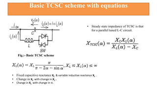
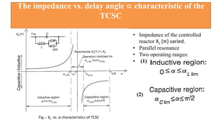
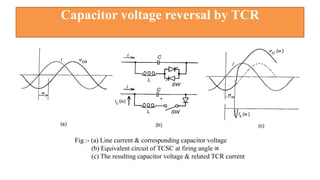
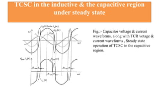
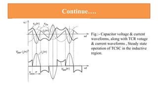
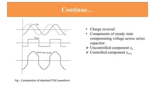
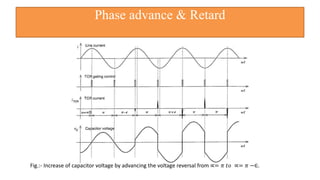
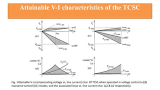
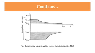
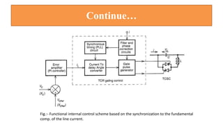
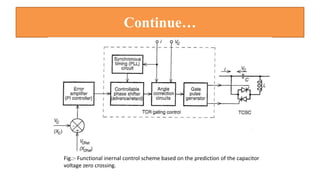
Thyristor Controlled Series
Capacitor (TCSC)
Prepared By : Karansinh Parmar
Flow of Presentation
• Basic TCSC scheme with equations
• The impedance vs. delay angle ∝ characteristic of the TCSC
• Capacitor voltage reversal by TCR
• TCSC in the capacitive & the inductive region under steady state
• Phase advance & retard
• Attainable V-I characteristics of the TCSC
• Harmonic voltages generation in TCSC
• Functional internal control schemes of the TCSC
• Conclusion
• Reference
Basic TCSC scheme with equations
Fig.:- Basic TCSC scheme
• Steady state impedance of TCSC is that
for a parallel tuned L-C circuit.
• Fixed capacitive reactance XC & variable inductive reactance XL .
• Change in XC with change in XL .
• Change in XL with change in ∝.
The impedance vs. delay angle ∝ characteristic of the
TCSC
Fig.:- XC vs. α characteristics of TCSC
• Impedance of the controlled
reactor XL (∝) varied.
• Parallel resonance
• Two operating ranges:
• (1)
(2)
Capacitor voltage reversal by TCR
Fig.:- (a) Line current & corresponding capacitor voltage
(b) Equivalent circuit of TCSC at firing angle ∝
(c) The resulting capacitor voltage & related TCR current
TCSC in the inductive & the capacitive region
under steady state
Fig.:- Capacitor voltage & current
waveforms, along with TCR votage &
current waveforms , Steady state
operation of TCSC in the capacitive
region.
Continue….
Fig.:- Capacitor voltage & current
waveforms, along with TCR votage
& current waveforms , Steady state
operation of TCSC in the inductive
region.
Continue…
• Charge reversal
• Components of steady state
compensating voltage across series
capacitor:
 Uncontrolled component Vco
 Controlled component VCTCR
Fig.:- Composition of idealized TCSC waveform
Phase advance & Retard
Fig.:- Increase of capacitor voltage by advancing the voltage reversal from ∝= 𝜋 𝑡𝑜 ∝= 𝜋 −∈.
Continue…
Fig.:- Decrease of capacitor voltage by retarding the voltage reversal from ∝= 𝜋 𝑡𝑜 ∝= 𝜋 +∈.
Attainable V-I characteristics of the TCSC
Fig.: Attainable V-I (compensating voltage vs, line current) char. Of TCSC when operated in voltage control (a1)&
reactance control (b1) modes, and the associated losss vs. line current char. (a2 & b2 respectively).
Continue…
Fig.:- Compensating reactance vs. Line current characteristics of the TCSC
Harmonic voltage generation in TCSC
Fig.:- Dominant harmonic voltages generated by TCSC at an XL/XC
ratio of 0.133.
• Effect of harmonics on TCSC
components
• Most important 3rd,5th & 7th
harmonics voltages
• 7th order harmonics
• Lower order harmonics
• Narrowing uncontrolled
capacitive band to a smaller
size for dynamic stability.
Functional internal control schemes of the TCSC
• Two types of internal control schemes:
Based on the synchronization to the fundamental comp. of the
line current.
Based on the prediction of the capacitor voltage zero crossing.
 The main consideration of TCSC internal control scheme to
ensure immunity to subsynchronous resonance.
Continue…
Fig.:- Functional internal control scheme based on the synchronization to the fundamental
comp. of the line current.
Continue…
Fig.:- Functional inernal control scheme based on the prediction of the capacitor
voltage zero crossing.
Conclusion
• Impedance of TCR does not significantly alter TCSC operation as it
is sufficiently smaller compared to capacitive reactance.
• Smaller XL is helpful in controlling period time of compensating
voltage & providing well-defined charge reversal.
• Smaller reactor L is also advantageous in protetive bypassing heavy
surge current during system fault.
• Smaller XL increases current harmonics generated by TCR.
• TCSC is usually applied to long, high impedance lines so line
current harmonics will be lower tan the ambient system.
Reference
Book:- “Understanding FACTS”
-By N.G.Hingorani & L.Gyughi
Thank you

TCSC

  • 1.
    Thyristor Controlled Series Capacitor(TCSC) Prepared By : Karansinh Parmar
  • 2.
    Flow of Presentation •Basic TCSC scheme with equations • The impedance vs. delay angle ∝ characteristic of the TCSC • Capacitor voltage reversal by TCR • TCSC in the capacitive & the inductive region under steady state • Phase advance & retard • Attainable V-I characteristics of the TCSC • Harmonic voltages generation in TCSC • Functional internal control schemes of the TCSC • Conclusion • Reference
  • 3.
    Basic TCSC schemewith equations Fig.:- Basic TCSC scheme • Steady state impedance of TCSC is that for a parallel tuned L-C circuit. • Fixed capacitive reactance XC & variable inductive reactance XL . • Change in XC with change in XL . • Change in XL with change in ∝.
  • 4.
    The impedance vs.delay angle ∝ characteristic of the TCSC Fig.:- XC vs. α characteristics of TCSC • Impedance of the controlled reactor XL (∝) varied. • Parallel resonance • Two operating ranges: • (1) (2)
  • 5.
    Capacitor voltage reversalby TCR Fig.:- (a) Line current & corresponding capacitor voltage (b) Equivalent circuit of TCSC at firing angle ∝ (c) The resulting capacitor voltage & related TCR current
  • 6.
    TCSC in theinductive & the capacitive region under steady state Fig.:- Capacitor voltage & current waveforms, along with TCR votage & current waveforms , Steady state operation of TCSC in the capacitive region.
  • 7.
    Continue…. Fig.:- Capacitor voltage& current waveforms, along with TCR votage & current waveforms , Steady state operation of TCSC in the inductive region.
  • 8.
    Continue… • Charge reversal •Components of steady state compensating voltage across series capacitor:  Uncontrolled component Vco  Controlled component VCTCR Fig.:- Composition of idealized TCSC waveform
  • 9.
    Phase advance &Retard Fig.:- Increase of capacitor voltage by advancing the voltage reversal from ∝= 𝜋 𝑡𝑜 ∝= 𝜋 −∈.
  • 10.
    Continue… Fig.:- Decrease ofcapacitor voltage by retarding the voltage reversal from ∝= 𝜋 𝑡𝑜 ∝= 𝜋 +∈.
  • 11.
    Attainable V-I characteristicsof the TCSC Fig.: Attainable V-I (compensating voltage vs, line current) char. Of TCSC when operated in voltage control (a1)& reactance control (b1) modes, and the associated losss vs. line current char. (a2 & b2 respectively).
  • 12.
    Continue… Fig.:- Compensating reactancevs. Line current characteristics of the TCSC
  • 13.
    Harmonic voltage generationin TCSC Fig.:- Dominant harmonic voltages generated by TCSC at an XL/XC ratio of 0.133. • Effect of harmonics on TCSC components • Most important 3rd,5th & 7th harmonics voltages • 7th order harmonics • Lower order harmonics • Narrowing uncontrolled capacitive band to a smaller size for dynamic stability.
  • 14.
    Functional internal controlschemes of the TCSC • Two types of internal control schemes: Based on the synchronization to the fundamental comp. of the line current. Based on the prediction of the capacitor voltage zero crossing.  The main consideration of TCSC internal control scheme to ensure immunity to subsynchronous resonance.
  • 15.
    Continue… Fig.:- Functional internalcontrol scheme based on the synchronization to the fundamental comp. of the line current.
  • 16.
    Continue… Fig.:- Functional inernalcontrol scheme based on the prediction of the capacitor voltage zero crossing.
  • 17.
    Conclusion • Impedance ofTCR does not significantly alter TCSC operation as it is sufficiently smaller compared to capacitive reactance. • Smaller XL is helpful in controlling period time of compensating voltage & providing well-defined charge reversal. • Smaller reactor L is also advantageous in protetive bypassing heavy surge current during system fault. • Smaller XL increases current harmonics generated by TCR. • TCSC is usually applied to long, high impedance lines so line current harmonics will be lower tan the ambient system.
  • 18.
  • 19.