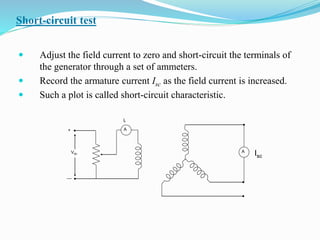
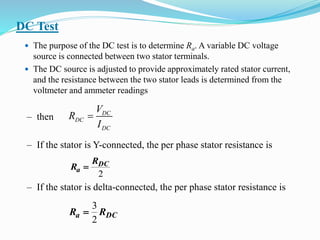
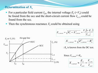
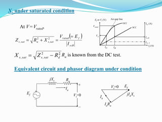
Downloaded 115 times

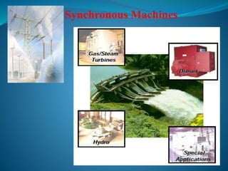
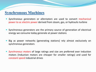
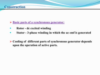
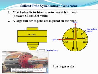
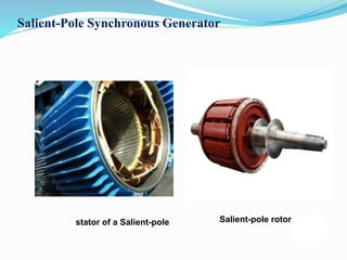
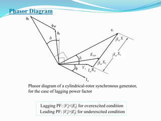
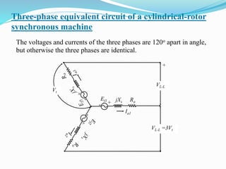
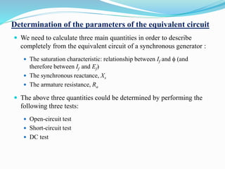
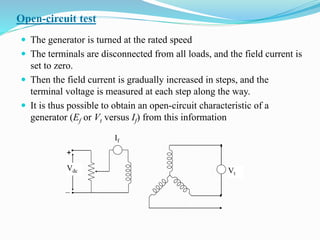


This document provides information about synchronous machines. It discusses: - Synchronous generators are used to generate electrical power from steam, gas, or hydraulic turbines. They are the primary source of power generation. - Synchronous machines can operate as generators or motors. Large synchronous motors are commonly used for constant speed industrial drives. - The document describes the construction, types, operation, and testing of synchronous machines. It provides equations to calculate parameters like voltage, frequency, reactance, and regulation from test data. - Parallel operation and synchronization of generators is discussed. Concepts like the infinite bus and power-angle characteristics are introduced.