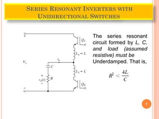
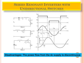
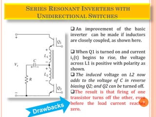
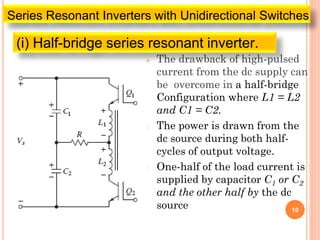
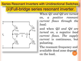
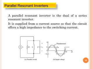
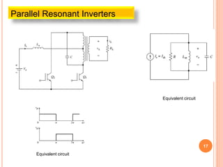
1
RESONANT PULSE INVERTERS
Dr. A. Ravi
Professor/EEE
FRANCIS XAVIER ENGINEERING COLLEGE
TIRUNELVELI- India
� To get the desired output voltage or current , the
switching devices in converters are controlled by with
a pulse-width-modulation (PWM) control.
� Hence the devices are undergone with high switch
high di/dt value also high voltage stresses resulting
Power loss of a devices.
� This power losses are increasing with switching
frequency.
� The electromagnetic interference is also produced due
to high di/dt and dv/dt in the converter waveforms.
2
WHY RESONANT PULSE CONVERTER- INTRODUCTION
� The disadvantages of PWM control can be
eliminated or minimized if the switching
devices are turned “on” and “off” when the
voltage across a device or its current becomes
zero.
� The voltage and current are forced to pass
through zero crossing by creating an LC-
resonant circuit, thereby called a resonant
pulse converter.
3
WHY RESONANT PULSE CONVERTER- INTRODUCTION
� Series resonant inverters
� Parallel resonant inverters
� Class E resonant converter
� Class E resonant rectifier
� Zero-voltage-switching (ZVS) resonant
converters
� Zero-current-switching (ZCS) resonant
converters
� Two-quadrant ZVS resonant converters
� Resonant dc-link inverters 4
RESONANT PULSE CONVERTER- TYPES
� The series resonant inverters produce a near
sinusoidal output voltage and the output
current depends on the load impedances.
� The parallel resonant inverter produces a
near sinusoidal output current and the output
voltage depends on the load impedances.
� These types of inverters are used for producing
high-frequency output voltage or current and
are often used as an intermediate between a dc
source and a dc power supply.
5
RESONANT PULSE CONVERTER-
� depending on the connections of the switching devices
and load. The series inverters may be classified into
two categories:
� 1. Series resonant inverters with unidirectional
switches
� 2. Series resonant inverters with bidirectional
switches
6
SERIES RESONANT INVERTERS
7
SERIES RESONANT INVERTERS WITH
UNIDIRECTIONAL SWITCHES
The series resonant
circuit formed by L, C,
and load (assumed
resistive) must be
Underdamped. That is,
8
SERIES RESONANT INVERTERS WITH
UNIDIRECTIONAL SWITCHES
Disadvantages: The power flow from the dc supply is discontinuous
9
SERIES RESONANT INVERTERS WITH
UNIDIRECTIONAL SWITCHES
 An improvement of the basic
inverter can be made if inductors
are closely coupled, as shown here.
 When Q1 is turned on and current
i1(t) begins to rise, the voltage
across L1 is positive with polarity as
shown.
 The induced voltage on L2 now
adds to the voltage of C in reverse
biasing Q2; and Q2 can be turned off.
The result is that firing of one
transistor turns off the other, even
before the load current reaches
zero.
 The drawback of high-pulsed
current from the dc supply can
be overcome in a half-bridge
Configuration where L1 = L2
and C1 = C2.
� The power is drawn from the
dc source during both half-
cycles of output voltage.
� One-half of the load current is
supplied by capacitor C1 or C2
and the other half by the dc
source 10
(i) Half-bridge series resonant inverter.
Series Resonant Inverters with Unidirectional Switches
� When Q1 and Q2 are turned
on, a positive resonant
current flows through the
load;
� and when Q3 and Q4 are
turned on, a negative load
current flows. The supply
current is continuous, but
pulsating.
� The resonant frequency and
available dead zone depend
on the load. 11
(ii)Full-bridge series resonant inverter.
Series Resonant Inverters with Unidirectional Switches
� For the resonant inverters with
unidirectional switches, the power devices
have to be turned on in every half-cycle of
output voltage.
� This limits the inverter frequency and the
amount of energy transfer from the source to
the load. In addition, the devices are
subjected to high peak reverse voltage.
12
Series Resonant Inverters with Unidirectional Switches
13
Series Resonant Inverters with Bidirectional Switches
• When device Q1 is turned on, a resonant pulse of current flows and
Q2 is self-commutated at t = t1.
• However, the resonant oscillation continues through diode D1 until
the current falls again to zero at the end of a cycle.
14
Series Resonant Inverters with Bidirectional Switches
Half-bridge series inverters with bidirectional switches.
15
Full-bridge series inverters with bidirectional switches.
Series Resonant Inverters with Bidirectional Switches
� A parallel resonant inverter is the dual of a series
resonant inverter.
� It is supplied from a current source so that the circuit
offers a high impedance to the switching current.
16
Parallel Resonant Inverters
17
Parallel Resonant Inverters
Equivalent circuit
Equivalent circuit
REFERENCE
18
Power Electronics Devices, Circuits, and
Applications
FOURTH EDITION
Muhammad H. Rashid
19

Resonant Inverters

  • 1.
    1 RESONANT PULSE INVERTERS Dr.A. Ravi Professor/EEE FRANCIS XAVIER ENGINEERING COLLEGE TIRUNELVELI- India
  • 2.
    � To getthe desired output voltage or current , the switching devices in converters are controlled by with a pulse-width-modulation (PWM) control. � Hence the devices are undergone with high switch high di/dt value also high voltage stresses resulting Power loss of a devices. � This power losses are increasing with switching frequency. � The electromagnetic interference is also produced due to high di/dt and dv/dt in the converter waveforms. 2 WHY RESONANT PULSE CONVERTER- INTRODUCTION
  • 3.
    � The disadvantagesof PWM control can be eliminated or minimized if the switching devices are turned “on” and “off” when the voltage across a device or its current becomes zero. � The voltage and current are forced to pass through zero crossing by creating an LC- resonant circuit, thereby called a resonant pulse converter. 3 WHY RESONANT PULSE CONVERTER- INTRODUCTION
  • 4.
    � Series resonantinverters � Parallel resonant inverters � Class E resonant converter � Class E resonant rectifier � Zero-voltage-switching (ZVS) resonant converters � Zero-current-switching (ZCS) resonant converters � Two-quadrant ZVS resonant converters � Resonant dc-link inverters 4 RESONANT PULSE CONVERTER- TYPES
  • 5.
    � The seriesresonant inverters produce a near sinusoidal output voltage and the output current depends on the load impedances. � The parallel resonant inverter produces a near sinusoidal output current and the output voltage depends on the load impedances. � These types of inverters are used for producing high-frequency output voltage or current and are often used as an intermediate between a dc source and a dc power supply. 5 RESONANT PULSE CONVERTER-
  • 6.
    � depending onthe connections of the switching devices and load. The series inverters may be classified into two categories: � 1. Series resonant inverters with unidirectional switches � 2. Series resonant inverters with bidirectional switches 6 SERIES RESONANT INVERTERS
  • 7.
    7 SERIES RESONANT INVERTERSWITH UNIDIRECTIONAL SWITCHES The series resonant circuit formed by L, C, and load (assumed resistive) must be Underdamped. That is,
  • 8.
    8 SERIES RESONANT INVERTERSWITH UNIDIRECTIONAL SWITCHES Disadvantages: The power flow from the dc supply is discontinuous
  • 9.
    9 SERIES RESONANT INVERTERSWITH UNIDIRECTIONAL SWITCHES  An improvement of the basic inverter can be made if inductors are closely coupled, as shown here.  When Q1 is turned on and current i1(t) begins to rise, the voltage across L1 is positive with polarity as shown.  The induced voltage on L2 now adds to the voltage of C in reverse biasing Q2; and Q2 can be turned off. The result is that firing of one transistor turns off the other, even before the load current reaches zero.
  • 10.
     The drawbackof high-pulsed current from the dc supply can be overcome in a half-bridge Configuration where L1 = L2 and C1 = C2. � The power is drawn from the dc source during both half- cycles of output voltage. � One-half of the load current is supplied by capacitor C1 or C2 and the other half by the dc source 10 (i) Half-bridge series resonant inverter. Series Resonant Inverters with Unidirectional Switches
  • 11.
    � When Q1and Q2 are turned on, a positive resonant current flows through the load; � and when Q3 and Q4 are turned on, a negative load current flows. The supply current is continuous, but pulsating. � The resonant frequency and available dead zone depend on the load. 11 (ii)Full-bridge series resonant inverter. Series Resonant Inverters with Unidirectional Switches
  • 12.
    � For theresonant inverters with unidirectional switches, the power devices have to be turned on in every half-cycle of output voltage. � This limits the inverter frequency and the amount of energy transfer from the source to the load. In addition, the devices are subjected to high peak reverse voltage. 12 Series Resonant Inverters with Unidirectional Switches
  • 13.
    13 Series Resonant Inverterswith Bidirectional Switches • When device Q1 is turned on, a resonant pulse of current flows and Q2 is self-commutated at t = t1. • However, the resonant oscillation continues through diode D1 until the current falls again to zero at the end of a cycle.
  • 14.
    14 Series Resonant Inverterswith Bidirectional Switches Half-bridge series inverters with bidirectional switches.
  • 15.
    15 Full-bridge series inverterswith bidirectional switches. Series Resonant Inverters with Bidirectional Switches
  • 16.
    � A parallelresonant inverter is the dual of a series resonant inverter. � It is supplied from a current source so that the circuit offers a high impedance to the switching current. 16 Parallel Resonant Inverters
  • 17.
  • 18.
    REFERENCE 18 Power Electronics Devices,Circuits, and Applications FOURTH EDITION Muhammad H. Rashid
  • 19.