1) For alternators to operate in parallel, they must be synchronized by having equal line voltage, frequency, phase sequence, phase angle, and waveform.
2) When alternators are synchronized and operating in parallel with no load, a circulating current will flow if their speeds or excitations differ slightly.
3) This circulating current acts to resynchronize the alternators by speeding up the slower one and slowing the faster one through their functioning as motor and generator respectively, until steady state is reached with no circulating current.
In this document
Powered by AI
Introduction to parallel operation of alternators, key synchronization conditions: line voltage, frequency, phase sequence, angle and waveform.
Analysis of E.M.F. in alternators A1 and A2 on no load, impact of prime mover and excitation changes, effects on circulating current.
Impact of resistance and reactance on synchronizing power, total synchronizing power, calculations for synchronizing torque.
Effects of excitation changes on E.M.F. magnitudes, resulting circulating currents and their effects on load percentages between the alternators.
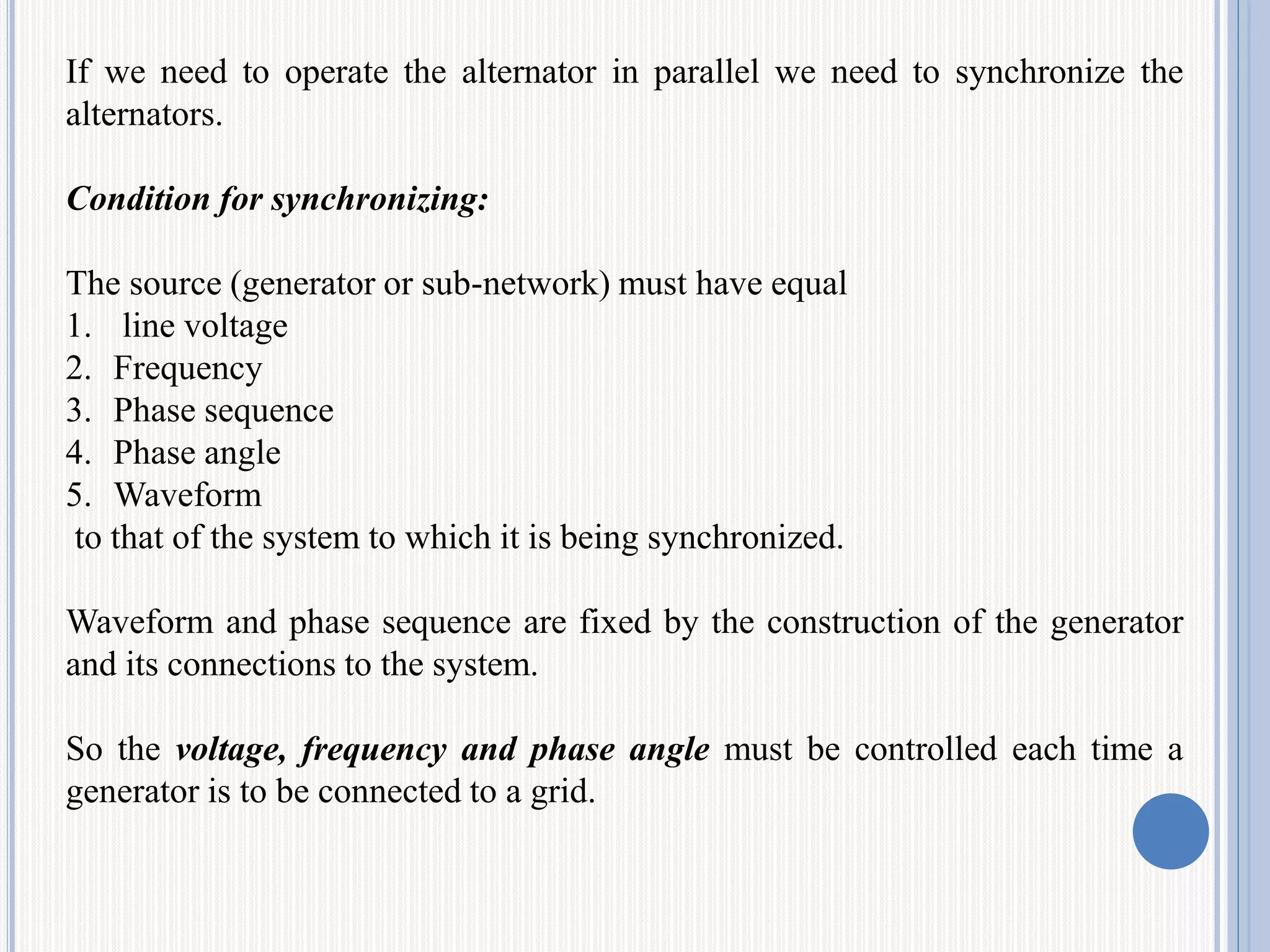
If we needto operate the alternator in parallel we need to synchronize the
alternators.
Condition for synchronizing:
The source (generator or sub-network) must have equal
1. line voltage
2. Frequency
3. Phase sequence
4. Phase angle
5. Waveform
to that of the system to which it is being synchronized.
Waveform and phase sequence are fixed by the construction of the generator
and its connections to the system.
So the voltage, frequency and phase angle must be controlled each time a
generator is to be connected to a grid.
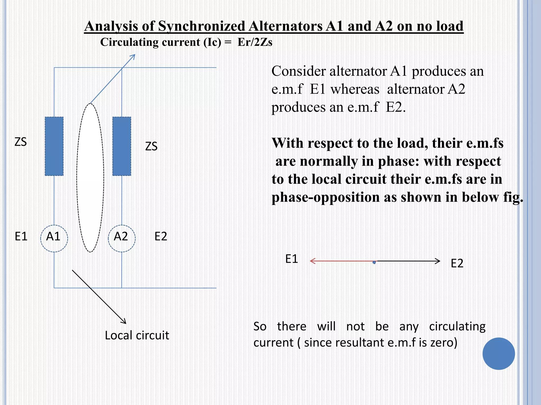
3.
A1 A2
ZS ZS
Localcircuit
Consider alternator A1 produces an
e.m.f E1 whereas alternator A2
produces an e.m.f E2.
With respect to the load, their e.m.fs
are normally in phase: with respect
to the local circuit their e.m.fs are in
phase-opposition as shown in below fig.
E1 E2
So there will not be any circulating
current ( since resultant e.m.f is zero)
E1 E2
Circulating current (Ic) = Er/2Zs
Analysis of Synchronized Alternators A1 and A2 on no load
4.
Let us considertwo abnormal conditions on no-load
1)Change in prime mover
2)Change in Excitation
5.
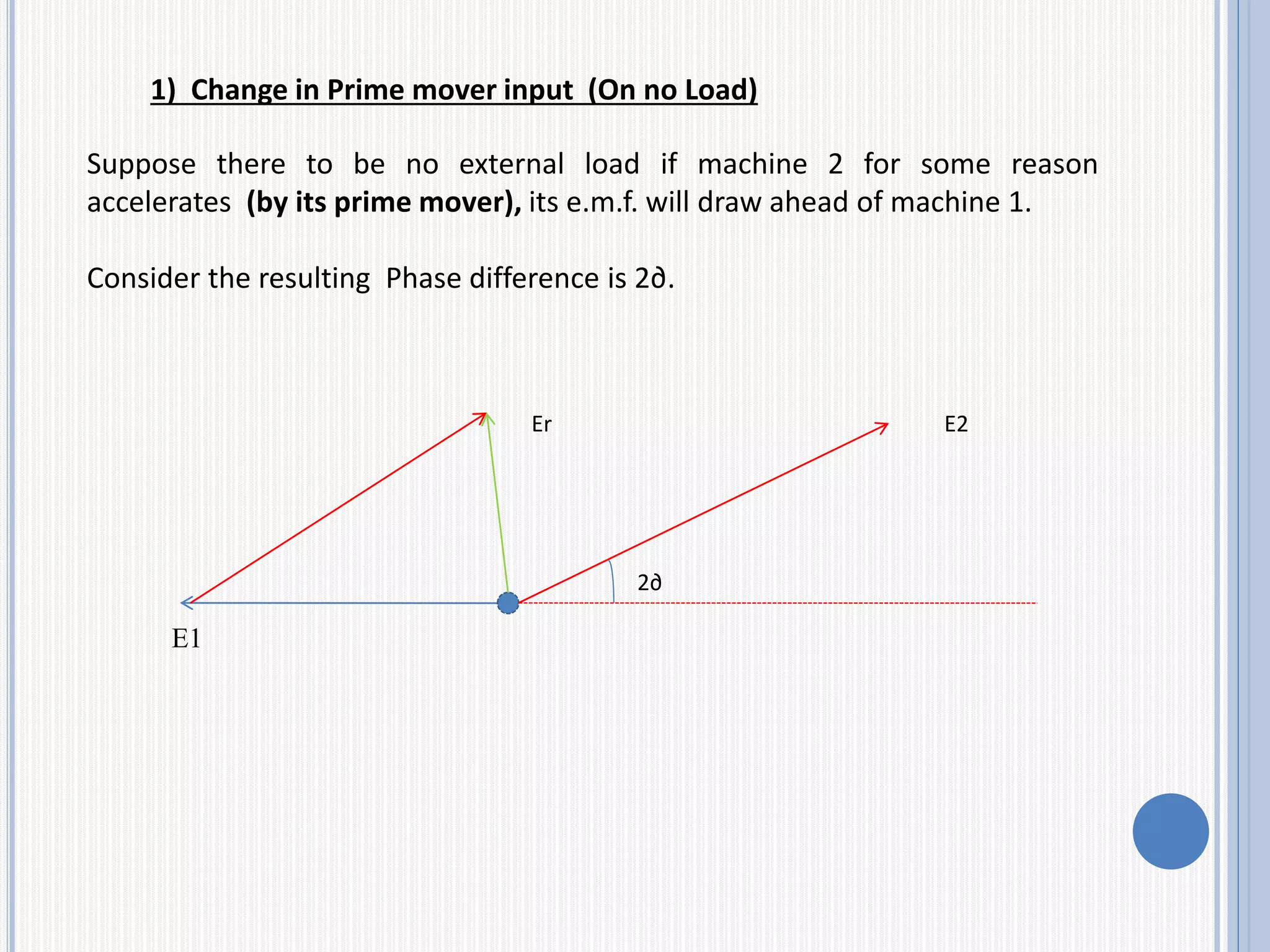
Suppose there tobe no external load if machine 2 for some reason
accelerates (by its prime mover), its e.m.f. will draw ahead of machine 1.
Consider the resulting Phase difference is 2∂.
E1
2∂
E2Er
1) Change in Prime mover input (On no Load)
6.
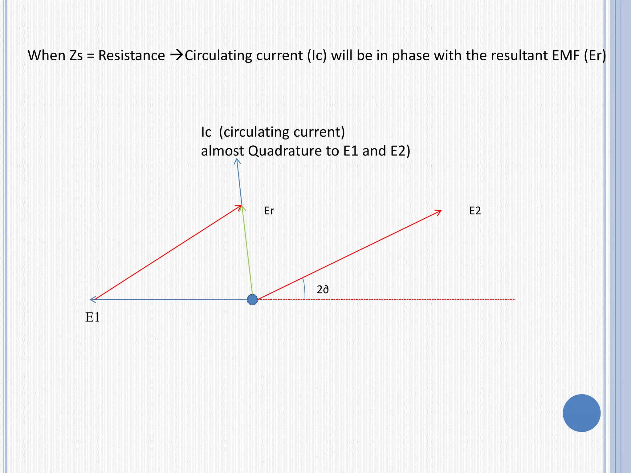
When Zs =Resistance Circulating current (Ic) will be in phase with the resultant EMF (Er)
E1
2∂
E2Er
Ic (circulating current)
almost Quadrature to E1 and E2)
7.
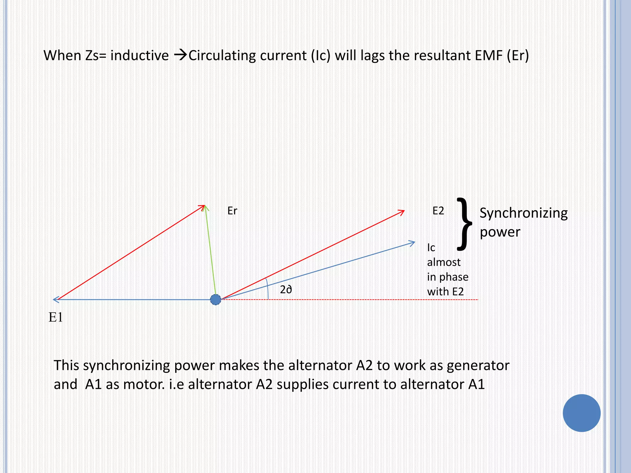
When Zs= inductiveCirculating current (Ic) will lags the resultant EMF (Er)
E1
2∂
E2Er
Ic
almost
in phase
with E2
}Synchronizing
power
This synchronizing power makes the alternator A2 to work as generator
and A1 as motor. i.e alternator A2 supplies current to alternator A1
8.
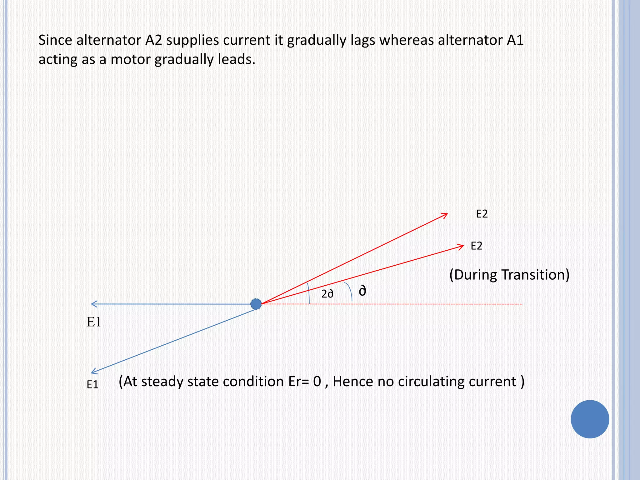
Since alternator A2supplies current it gradually lags whereas alternator A1
acting as a motor gradually leads.
E1
2∂
E2
E2
∂
E1
(During Transition)
(At steady state condition Er= 0 , Hence no circulating current )
9.
Thus the presenceof more resistance in the generators will
resist or oppose their synchronous operation. More reactance
in the generators can cause good reaction between the two
and help the generators to remain synchronism in spite of
any disturbance occurring in any one of the generators.
From phasor diagram , total synchronizing power, Maximum
synchronizing power and synchronizing torque can be calculated
10.
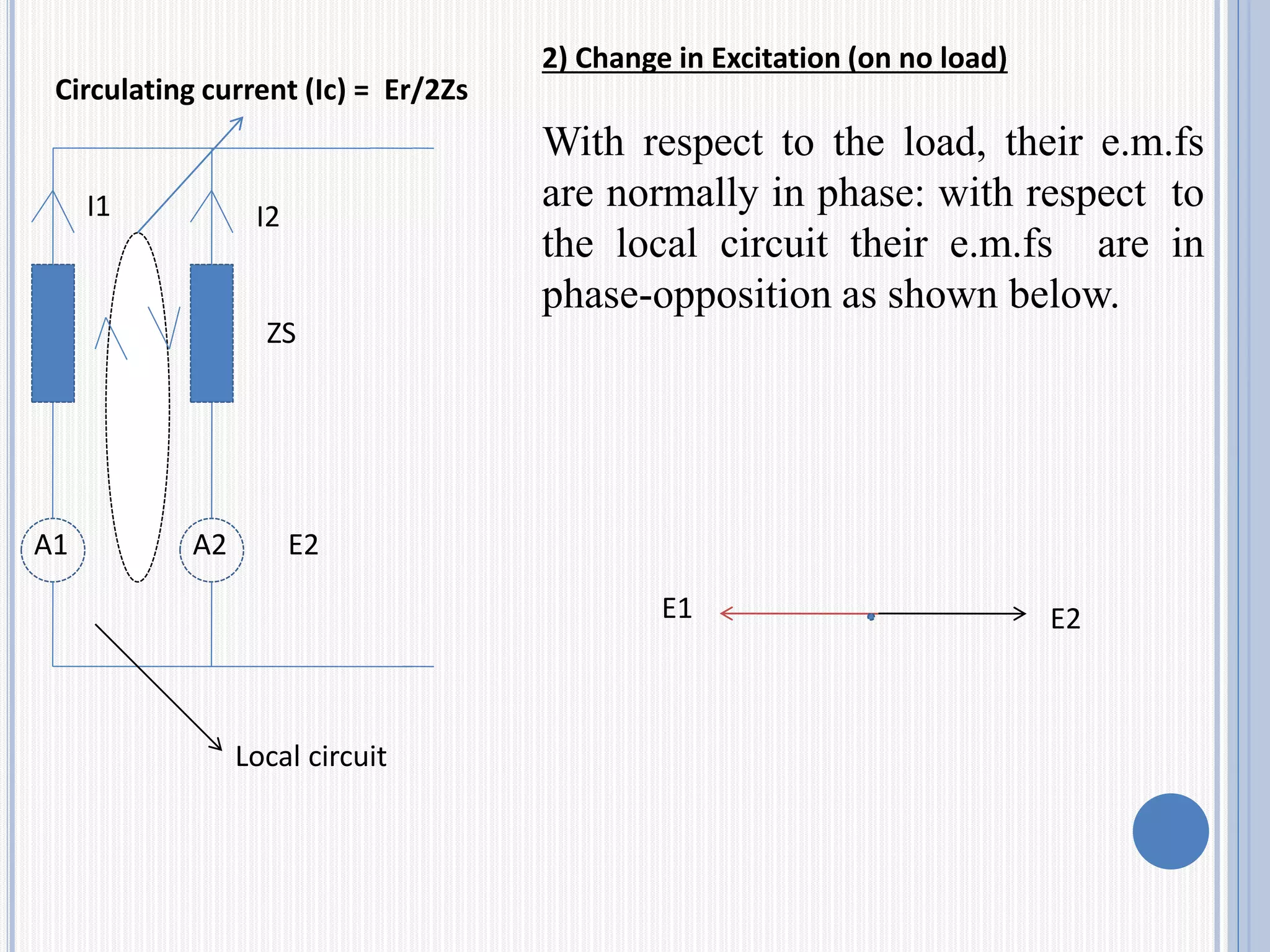
2) Change inExcitation (on no load)
With respect to the load, their e.m.fs
are normally in phase: with respect to
the local circuit their e.m.fs are in
phase-opposition as shown below.
A1 A2
ZS
Local circuit
E2
Circulating current (Ic) = Er/2Zs
E1 E2
I1 I2
11.
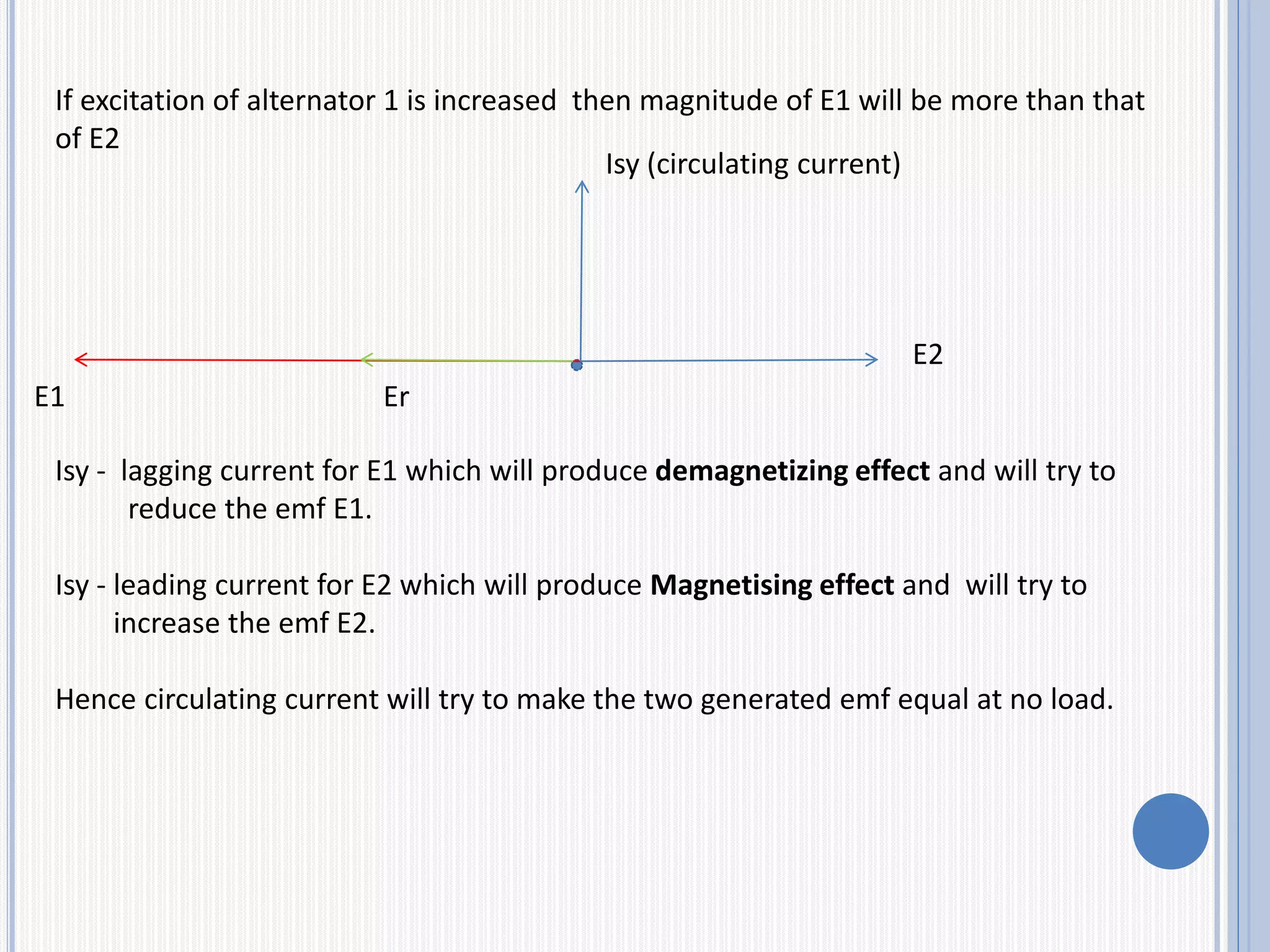
If excitation ofalternator 1 is increased then magnitude of E1 will be more than that
of E2
E2
E1 Er
Isy (circulating current)
Isy - lagging current for E1 which will produce demagnetizing effect and will try to
reduce the emf E1.
Isy - leading current for E2 which will produce Magnetising effect and will try to
increase the emf E2.
Hence circulating current will try to make the two generated emf equal at no load.
12.
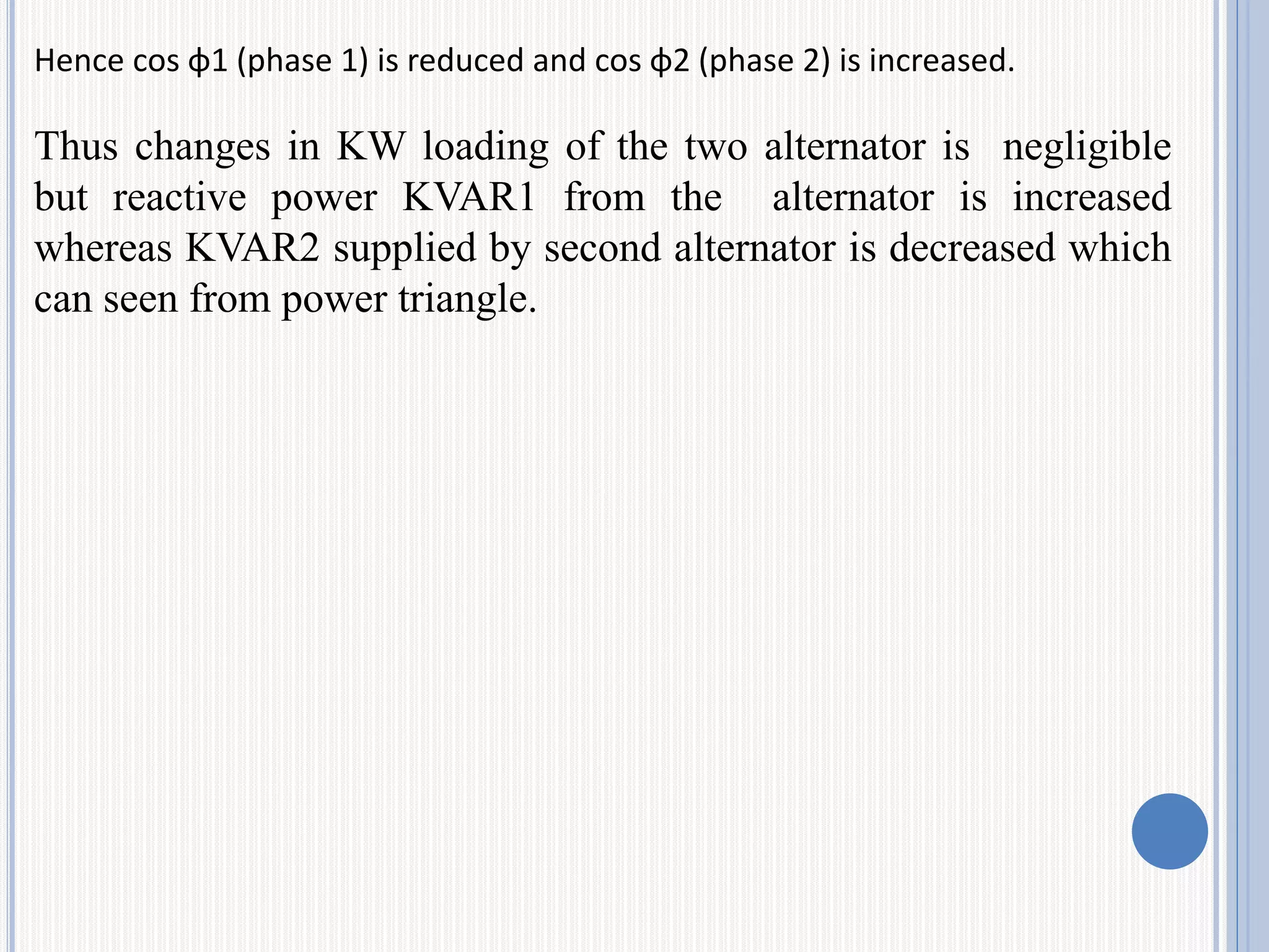
Hence cos φ1(phase 1) is reduced and cos φ2 (phase 2) is increased.
Thus changes in KW loading of the two alternator is negligible
but reactive power KVAR1 from the alternator is increased
whereas KVAR2 supplied by second alternator is decreased which
can seen from power triangle.