Downloaded 103 times
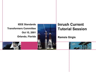
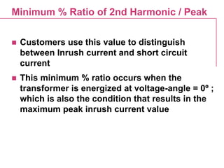
![Calculated Inrush Current Waveshape
0
200
400
600
800
1000
1200
1400
1600
1800
2000
0 5 10 15 20
Time [ms]
Amps](https://image.slidesharecdn.com/ieeeinrushtutorial-150608122454-lva1-app6891/85/Ieee-inrush-tutorial-4-320.jpg)
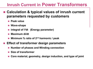
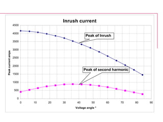
![Calculated Peak inrush current
0
200
400
600
800
1000
1200
1400
1600
1800
2000
0 20 40 60 80 100
Cycle
Current[A]](https://image.slidesharecdn.com/ieeeinrushtutorial-150608122454-lva1-app6891/85/Ieee-inrush-tutorial-5-320.jpg)

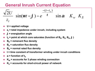
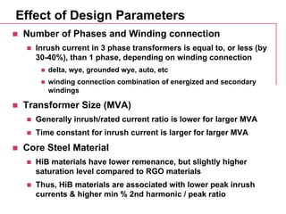
![Inrush Current for First Cycle
-2000
-1500
-1000
-500
0
500
1000
1500
2000
0 5 10 15 20
Time [ms]
Current[A]
-400
-300
-200
-100
0
100
200
300
400
di/dt[A/ms]
Inrush Current 1st Peak
di/dt of 1st Cycle
n Value used in setting size of vacuum switch](https://image.slidesharecdn.com/ieeeinrushtutorial-150608122454-lva1-app6891/85/Ieee-inrush-tutorial-10-320.jpg)


This document discusses inrush current in power transformers. It provides calculations and typical values for inrush current parameters such as peak value, wave shape, energy parameter, and maximum di/dt. It also examines the effect of transformer design parameters like the number of phases, winding connection, size, core material, geometry, design induction, and joint type on inrush current values. General equations are presented for calculating inrush current waveform based on factors like applied voltage, impedance, energization angle, and core material properties.


![Transformer Repair Workshop Report [EEE]](https://cdn.slidesharecdn.com/ss_thumbnails/transformerrepairworkshopeee-140621072318-phpapp01-thumbnail.jpg?width=640&height=640&fit=bounds)