The document discusses data download processes for various event loggers and disturbance recorders used in substations, highlighting their functions, applications, and operational concepts. It also covers critical operational guidelines for fault locators, synchronization, transformer parallel operations, and interlocking mechanisms for circuit breakers and isolators. Additionally, it provides insight into various electrical concepts, protection schemes, and practical calculations relevant to electrical systems.

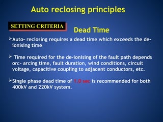
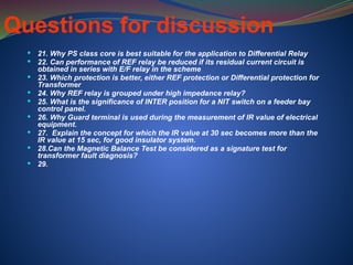
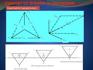
![Minimum Dead Time (IEEE)
System
Voltage
Minimum deionization time
[ms]
kV Based on Field
and
Laboratory
Tests
Based on
Operating
Experience
23 110 180
46 120 200
69 130 210
115 150 230
132 160 240
230 210 280
345 260 340
400 280 370
500 330 420](https://image.slidesharecdn.com/4876979-240822173418-723c19ee/85/event-looger-Distrubance-Recorders-ppt-31-320.jpg)
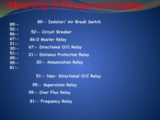
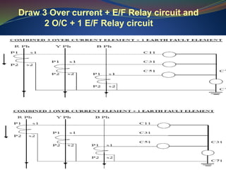
![Questions for discussion
11. Why the use of combined instrument transformer is not gaining
popularity in India.
12. Why the spring-spring mechanism is gaining popularity in Breaker
Technology
13. Which circuit is important for supervision of breaker trip coil status?
(Pre-close supervision, post-close supervision)
14 Why DC Voltage is preferable for the protection and control circuit in
System Network
15. What are the reasons for variation of voltage due to increase of
load in the system
16. Most of the Power transformers are of Y connected, why not ∆
connected
17. We know that Voltage is directly proportional to frequency, but
sometimes voltage decreases but not the frequencies why?
18. In case of 3ph, 4wire system, and the neutral is disconnected. Why
the meter showing the value above 350volts in 2 phases?
19. Why REF protection is not considered as 100% protection to the
equipment winding
20. Why PT of different rating is used [110V /√3 and 110V]](https://image.slidesharecdn.com/4876979-240822173418-723c19ee/85/event-looger-Distrubance-Recorders-ppt-46-320.jpg)