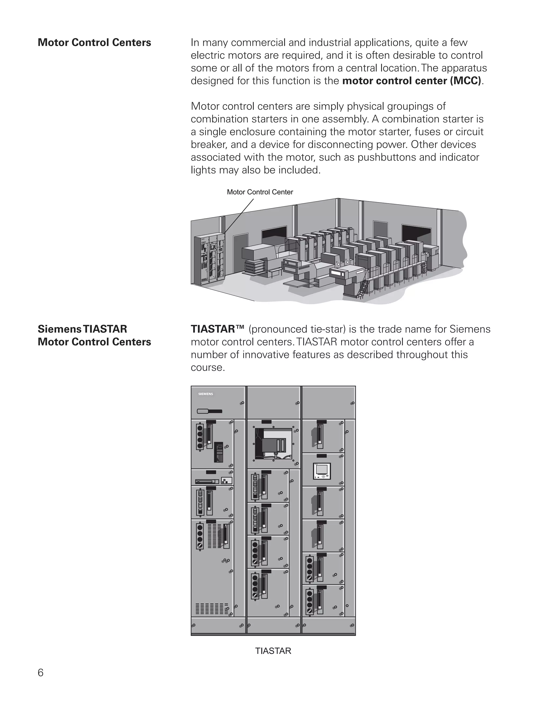
SlideShare a Scribd company logo
1 of 72
Download to read offline
Table of Contents
Introduction...............................................................................2
Motor Control............................................................................4
Power Supplies..........................................................................8
Design Standards....................................................................12
Need for Circuit Protection......................................................13
Overcurrent Protection Devices...............................................18
Motor Control Centers.............................................................22
TIASTAR MCC Construction....................................................33
Combination Motor Control Units............................................44
Motor Starters.........................................................................51
Pilot Devices............................................................................57
Circuit Breakers.......................................................................59
OtherTypes of Devices in MCCs.............................................61
TIASTAR Ordering Information................................................64
Review Answers......................................................................66
Final Exam...............................................................................67
quickSTEP Online Courses......................................................72
Introduction
Welcome to another course in the STEP series, Siemens
Technical Education Program, designed to prepare our
distributors to sell Siemens Energy  Automation products
more effectively.This course covers Basics of Motor Control
Centers.
Upon completion of Basics of Motor Control Centers, you
should be able to:
•	 Explain the role of motor control centers in a distribution
system
•	 Define a motor control center according to NEMA and UL
•	 Explain the need for circuit protection
•	 Identify various components of a motor control center
•	 Explain the difference between the various classifications
and types of motor control center wiring
•	 Explain features of theTIASTAR motor control centers
This knowledge will help you better understand customer
applications. In addition, you will be better prepared to describe
motor control products to customers.You should complete
Basics of Electricity and Basics of Control Components
before attempting Basics of Motor Control Centers.
If you are an employee of a Siemens Energy  Automation
authorized distributor, fill out the final exam tear-out card and
mail in the card. We will mail you a certificate of completion if
you score a passing grade. Good luck with your efforts.
Siemens is a trademark of Siemens AG. Product names
mentioned may be trademarks or registered trademarks of their
respective companies. Specifications are subject to change
without notice.
National Electrical Code® and NEC® are registered trademarks
of the National Fire Protection Association, Quincy, MA 02169.
Portions of the National Electrical Code are reprinted with
permission from NFPA 70-2008, National Electrical Code®,
Copyright ©2007, National Fire Protection Association, Quincy,
MA 02169.This reprinted material is not the complete and
official position of the National Fire Protection Association on
the referenced subject which is represented by the standard in
its entirety.
NEMA® is a registered trademark and service mark of the
National Electrical Manufacturers Association, Rosslyn, VA
22209.
Underwriters Laboratories Inc. and UL are registered
trademarks of Underwriters Laboratories Inc., Northbrook, IL
60062-2096.
Other trademarks are the property of their respective owners.
Motor Control
Power distribution systems used in large commercial and
industrial applications can be complex. Power may be
distributed through switchgear, switchboards, transformers,
and panelboards. Power distributed throughout a commercial or
industrial application is used for a variety of applications such as
heating, cooling, lighting, and motor-driven machinery.
Feeder Busway
Motor Control Center
Switchboard
Panelboard
Transformer
Panelboard
480 VAC
480 VAC
480 VAC
120 VAC
480 VAC
480 VAC
From Utility
Outdoor
Feeder
Busway
Basic Motor Control	 Wherever motors are used, they must be controlled. In Basics
of Control Components you learned how various control
products are used to control the operation of motors.The most
basic type of AC motor control, for example, involves turning
the motor on and off.This is often accomplished using a motor
starter made up of a contactor and an overload relay.
	 The contactor’s contacts are closed to start the motor
and opened to stop the motor.This is accomplished
electromechanically using start and stop pushbuttons or other
pilot devices wired to control the contactor.
The overload relay protects the motor by disconnecting power
to the motor when an overload condition exists. Although the
overload relay provides protection from overloads, it does not
provide short-circuit protection for the wiring supplying power
to the motor. For this reason, a circuit breaker or fuses are also
used.
Circuit Breaker
L1
L2
L3
Motor Starter
Contactor
Overload Relay
Motor
OL
OL
OL
M
M
M
Start
Pushbutton
Stop
Pushbutton
Ma
M
Auxiliary Contactor Contact
(Holding Circuit)
Contactor Coil
Overload Contact
150A
OFF O
ION
Type/Tipo NDG
Frame DG
AC Motor
Typically one motor starter controls one motor. When only a
few geographically dispersed AC motors are used, the circuit
protection and control components may be located in a panel
near the motor.
Short Circiut
Protection
Disconnect
Motor Starter
OFF
ON
OFF
START
STOP
Motor Control Centers	 In many commercial and industrial applications, quite a few
electric motors are required, and it is often desirable to control
some or all of the motors from a central location.The apparatus
designed for this function is the motor control center (MCC).
	 Motor control centers are simply physical groupings of
combination starters in one assembly. A combination starter is
a single enclosure containing the motor starter, fuses or circuit
breaker, and a device for disconnecting power. Other devices
associated with the motor, such as pushbuttons and indicator
lights may also be included.
Motor Control Center
SiemensTIASTAR	 TIASTAR™ (pronounced tie-star) is the trade name for Siemens
Motor Control Centers 	 motor control centers.TIASTAR motor control centers offer a
number of innovative features as described throughout this
course.
	
TIASTAR
Advantages of 	 Some of the advantages of usingTIASTAR motor control
SiemensTIASTAR MCCs	 centers are:
•	 Faster and easier installation and wiring
•	 Centralized motor control
•	 Generally less total space is required
•	 Neat, attractive appearance
•	 Simplicity in adding special components such as service
entrance switches, load centers, and transformers
•	 Ease of future modifications, such as increasing the size of
the starters, adding additional starters, or adding additional
vertical sections.
TIA 	 The TIA portion of theTIASTAR name stands forTotally
Integrated Automation.TIA is more than a concept. It is a
strategy developed by Siemens that emphasizes the seamless
integration of automation, networking, drive, and control
products.TheTIA strategy has been the cornerstone of
development for a wide variety of Siemens products.
	 TIA is important not just because it simplifies the engineering,
startup, and maintenance of systems developed using Siemens
products, but also because it lowers the life-cycle costs for
systems incorporating these products. Additionally, by reducing
engineering and startup of systems,TIA helps Siemens
customers reduce time to market and improve overall financial
performance.
Power Supplies
The major source of electrical power used by motor control
centers is an AC generator located at a power generating
facility.  AC generators operate on the theory of electromagnetic
induction.This simply means that when conductors are
moved through a magnetic field, a voltage is induced into the
conductors. A basic generator consists of a magnetic field, an
armature, slip rings, brushes, and some type of resistive load.
An armature is any number of conductive wires (conductors)
wound in loops which rotate through the magnetic field. For
simplicity, one loop is shown.
If the rotation of the AC generator were tracked through a
complete revolution of 360°, it could be seen that during
the first quarter of a revolution voltage would increase until
it reached a maximum positive value at 90°. Voltage would
decrease during the second quarter of revolution until it reached
zero at 180°. During the third quarter of a revolution voltage
would increase in the opposite direction until it reached a
maximum negative value at 270°. During the last quarter of a
revolution voltage would decrease until it reached zero at 360°.
This is one complete cycle or one complete alternation between
positive and negative.
If the armature of the simple AC generator shown here rotates
3600 times per minute (3600 RPM), the generator produces 60
cycles of voltage per second, or 60 hertz (Hz). In practice, AC
generators typically have two or three pairs of electromagnetic
poles, allowing the generation of 60 Hz voltage at a slower
rotational speed.
Three-Phase Voltage	 In most large commercial and industrial motor applications,
three-phase voltage is used. In a three-phase system, the
generator produces three voltages. Each voltage phase rises
and falls at the same frequency (60 Hz in the U.S., 50 Hz in
many other countries); however, the phases are offset by 120°
from each other.
The motor control center receives this power through complex
distribution systems which include power distribution lines,
transformers, substations, and switchboards.Transformers used
with three-phase power require three interconnected coils in
both the primary and the secondary.These transformers can be
connected in either a wye or a delta configuration.The type of
transformer and the actual voltage depend on the requirements
and capability of the power company and the needs of the
customer.The following illustration shows examples of the
secondary windings of wye- and delta-connected transformers.
10
Motor Rotation	 Three-phase voltage is used throughout large commercial and
industrial facilities to run AC motors. An AC motor is made up
of a stationary member, called a stator, and a rotating member,
called a rotor.Three-phase AC power is applied to the stator
through the power connections.
Stator
Rotor
Power Connections
The direction a three-phase AC motor rotor turns depends
on the phase sequence of the incoming power supply. In the
following example, L1 (A) is connected to motor leadT1, L2 (B)
is connected to motor leadT2, and L3 (C) is connected to motor
leadT3. When power is applied through the “F” contacts, the
motor turns in a clockwise, or forward direction.
However, if any two of the three power supply leads are
reversed, the motor runs in the opposite direction. In this
example, when the F contacts open and the R contacts close,
L1 (A) is connected to motor leadT3, L2 (B) is connected to
motor leadT2, and L3 (C) is connected to motor leadT1. (L1 
and L3 have been reversed.) As a result, the motor runs in the
counterclockwise, or reverse direction.
11
Many applications are designed for forward and reverse
operation. An overhead crane, for example, might use the
forward direction to raise the crane and reverse direction to
lower the crane.
Overhead Crane
Review 1	
1.	 Which of the following is a advantage of using a
TIASTAR motor control center?
	 a.	Faster and easier installation and wiring
	 b.	Simplicity in adding special components
	 c.	Ease of future modifications
	 d.	All the above
2.	 TheTIA portion of theTIASTAR name stands for ______.
3.	 In most large commercial and industrial motor
applications, ________-phase voltage is used.
4.	 Motor rotation of a three-phase AC induction motor
can be reversed by reversing any ________ of the three
power supply leads.
12
Design Standards
Although several organizations are involved in establishing
standards for the design, construction, and application of motor
control centers, the primary standards discussed in this book
were established by UL, NEMA, and NFPA.  The following
organizations have established standards which may be applied
to motor control centers. It is beyond the scope of this course
to cover every standard; however, reference will be made
throughout the course to important standards with which
Siemens motor control centers comply.
UL	 Underwriters Laboratories (UL) is a private company that is
nationally recognized as an independent testing laboratory. UL
tests products for safety and products that pass UL tests can
carry a UL mark. Siemens motor control centers are designed
to UL 845 standards.
NEMA	 The National Electrical Manufacturers Association (NEMA)
is an organization that, among other things, develops standards
for electrical equipment.
NFPA	 The National Fire Protection Association (NFPA) is a
nonprofit organization which publishes the National Electrical
Code® (NEC®).The intent of the NEC® is to describe safe
electrical practices.
ANSI	 The American National Standards Institute (ANSI) is a
nongovernmental organization that facilitates the development
of standards by establishing a consensus among qualified
groups.
IEEE	 The Institute of Electrical and Electronic Engineers (IEEE) is
an organization open to individual membership and provides a
variety of services for its members. It also develops numerous
standards for electrical and electronic equipment and practices.
IEC	 The International Electrotechnical Commission (IEC)
is an organization based in Geneva, Switzerland with over
50 member nations. IEC writes standards for electrical and
electronic equipment practices.
13
Need for Circuit Protection
Current andTemperature	 Current flow in a conductor always generates heat.The greater
the current flow in any one size conductor, the hotter the
conductor. Excess heat is damaging to electrical components
and conductor insulation. For that reason, conductors have
a rated, continuous current-carrying capacity or ampacity.
Overcurrent protection devices, such as fuses, are used to
protect conductors from excessive current flow.
Normal Current Flow
Excessive Current Flow
Excessive current is referred to as overcurrent.The National
Electrical Code® defines overcurrent as any current in excess of
the rated current of equipment or the ampacity of a conductor.
It may result from overload, short circuit, or ground fault (Article
100-definitions).
Reprinted with permission from NFPA 70-2008, the National Electrical
Code®, Copyright ©2007, National Fire Protection Association, Quincy, MA
02169.This reprinted material is not the complete and official position of the
National Fire Protection Association which is represented by the standard in
its entirety.
14
Overloads	 An overload occurs when too many devices are operated on
a single circuit or when electrical equipment is made to work
harder than its rated design. For example, a motor rated for 10
amperes may draw 20, 30, or more amperes in an overload
condition. In the following illustration, a package has become
jammed on a conveyor, causing the motor to work harder and
draw more current. Because the motor is drawing more current,
it heats up. Damage will occur to the motor in a short time if
the problem is not corrected or if the circuit is not shut down by
an overcurrent protection device.
Conductor Insulation	 Motors, of course, are not the only devices that require circuit
protection for an overload condition. Every circuit requires some
form of protection against overcurrent. Heat is one of the major
causes of insulation failure of any electrical component. High
levels of heat to insulated wire can cause the insulation to
breakdown, melt, or flake off, exposing conductors.
Insulation Affected by Heat
Good Insulation
15
Short Circuits	 When two bare conductors touch, a short circuit occurs. When
a short circuit occurs, resistance drops to almost zero. Short
circuit current can be thousands of times higher than normal
operating current.
Ohm’s Law demonstrates the relationship of current, voltage,
and resistance. For example, a 240 volt motor with 24 Ω (ohms)
of resistance would normally draw 10 amperes of current.
When a short circuit develops, resistance drops. If resistance
drops to 24 milliohms, current will be 10,000 amperes.
Short-Circuit Current on	 When a short circuit occurs, current will continue to flow
Unprotected Electrical 	 in an unprotected electrical circuit.The peak short-circuit
Circuits	 current of the first cycle is the greatest and is referred to as
peak let-thru current (IP).The force of this current can cause
damage to wires, switches, and other electrical components of
a circuit.
16
Associated with the peak let-thru current is peak let-thru
energy (I
2
t). For an unprotected circuit, this energy is often
capable of dramatic destruction of equipment and is a serious
safety concern.
Short-Circuit Current on 	 Fortunately, if a circuit has a properly applied overcurrent
Protected Electrical Circuits	 protection device, the device will  open the circuit quickly when
if a short circuit occurs, limiting peak let-thru current (IP) and
energy (I
2
t).
Circuit protection would be unnecessary if overloads and short
circuits could be eliminated. Unfortunately, overloads and short
circuits do occur.
NEC® Article 240 	 Article 240 of the NEC® covers overcurrent protection.You are
encouraged to become familiar with this material. Article 240.1 
states that:
	 Overcurrent protection for conductors and equipment is
provided to open the circuit if the current reaches a value that
will cause an excessive or dangerous temperature in conductors
or conductor insulation.
Reprinted with permission from NFPA 70-2008, the National Electrical
Code®, Copyright ©2007, National Fire Protection Association, Quincy, MA
02169.This reprinted material is not the complete and official position of the
National Fire Protection Association which is represented by the standard in
its entirety.
17
NEC® Article 430.94	 The National Electrical Code® requires overcurrent protection
for motor control centers. NEC® Article 430.94 states:
Motor control centers shall be provided with overcurrent
protection in accordance with Parts I, II, and IX of Article 240.
The ampere rating or setting of the overcurrent protective
device shall not exceed the rating of the common power
bus.This protection shall be provided by (1) an overcurrent
protective device located ahead of the motor control center
or (2) a main overcurrent protective device located within the
motor control center.
There are two ways Article 430.94 can be met. An overcurrent
protection device can be installed ahead of the motor control
center. A switchboard, for example, located upstream of the
motor control center may contain the overcurrent protection
device for the motor control center.The second way to meet
this requirement is to install a main overcurrent protection
device within the motor control center.
Reprinted with permission from NFPA 70-2008, the National Electrical
Code®, Copyright ©2007, National Fire Protection Association, Quincy, MA
02169.This reprinted material is not the complete and official position of the
National Fire Protection Association which is represented by the standard in
its entirety.
18
Overcurrent Protection Devices
An overcurrent protection device must be able to recognize
the difference between an overcurrent and short circuit and
respond in the proper way. Slight overcurrents can be allowed
to continue for some period of time; but as the current
magnitude increases, the protection device must open faster.
Short circuits must be interrupted instantly.
Fusible Disconnect Switch	 A fusible disconnect switch is one type of device used to
provide overcurrent protection. Properly sized fuses located
in the switch open the circuit when an overcurrent condition
exists.
Fusible Disconnect Switch
Fuses
Fuse	 A fuse is a one-shot device.The heat produced by overcurrent
causes the current carrying element to melt open,
disconnecting the load from the source voltage.
Fuse During Fault Fuse After Fault
19
Non-time-Delay Fuses	 Non-time-delay fuses provide excellent short-circuit
protection. When an overcurrent occurs, heat builds up rapidly
in the fuse. Non-time-delay fuses usually hold 500% of their
rating for ­approximately one-fourth second, after which the
current-carrying element melts.This means that these fuses
should not be used in motor circuits which often have inrush
currents greater than 500%.
Time-Delay Fuses	 Time-delay fuses provide overload and short-circuit protection.
Time-delay fuses usually allow several times the rated current
to flow for a short time to allow a motor to start.
Fuse Classes	 Fuses are grouped into classes based on their operating and
construction characteristics. Each class has an interrupting
rating (IR) in amperes which is the amount of fault current this
class of fuses is capable of interrupting without destroying the
fuse casing. Fuses are also rated according to the maximum
continuous current and maximum voltage they can handle.
Underwriters Laboratories (UL) establishes and standardizes
basic performance and physical specifications to develop
its safety-test procedures.These standards have resulted in
distinct classes of low-voltage fuses rated at 600 volts or less.
The following chart lists the fuse class and its ratings.
20
Circuit Breakers	 Another device used for overcurrent protection is a circuit
breaker.The National Electrical Code® defines a circuit
breaker as a device designed to open and close a circuit by
nonautomatic means and to open the circuit automatically on
a predetermined overcurrent without damage to itself when
properly applied within its rating (Article 100-definitions).
Circuit breakers provide a manual means of energizing and
de-energizing a circuit. In addition, circuit breakers provide
automatic overcurrent protection of a circuit. One key advantage
of a circuit breaker is that it allows a circuit to be reactivated
quickly after a short circuit or overload is cleared by simply
resetting the breaker.
O
N
O
F
F
l
O
100
100 Amp
Type/Tipo NEGFrame-EG
Circuit Breaker
Ampere Rating	 Like fuses, every circuit breaker has ampere, voltage, and
interrupting ratings.The ampere rating is the maximum
continuous current a circuit breaker can carry without exceeding
its rating. In general, the circuit breaker ampere rating should
not exceed the conductor ampere rating. For example, if the
conductor is rated for 20 amps, the circuit breaker rating should
not exceed 20 amps. Siemens breakers are rated on the basis
of using 60° C or 75° C conductors.This means that even if
a conductor with a higher temperature rating were used, the
ampacity of the conductor must be figured on its 60° C or 75° C
rating.
Voltage Rating	 The voltage rating of the circuit breaker must be at least equal
to the supply voltage.The voltage rating of a circuit breaker can
be higher than the supply voltage, but never lower. For example,
a 480 VAC circuit breaker could be used on a 240 VAC circuit. A
240 VAC circuit breaker could not be used on a 480 VAC circuit.
Reprinted with permission from NFPA 70-2008, the National Electrical
Code®, Copyright ©2007, National Fire Protection Association, Quincy, MA
02169.This reprinted material is not the complete and official position of the
National Fire Protection Association which is represented by the standard in
its entirety..
21
The voltage rating is a function of the circuit breaker’s ability to
suppress the internal arc that occurs when the circuit breaker’s
contacts open.
Fault-Current	 Circuit breakers are also rated according to the level of fault
Interrupting Rating	 current they can interrupt. When applying a circuit breaker, one
must be selected to sustain the largest potential short-circuit
current which can occur in the selected application. Siemens
circuit breakers have interrupting ratings from 10,000 to
200,000 amps.
Review 2
1.	 ________ is a private company that is nationally
recognized as an independent testing laboratory.
2.	 An ________ occurs when too many devices are
operated on a single circuit or when electrical
equipment is made to work harder than its rated
design.
3.	 Time-delay fuses provide overload and ________
protection.
4.	 Class R fuses have an interrupting rating of ________
amps.
5.	 The ________ rating of a circuit breaker must be at least
equal to the supply voltage.
22
Motor Control Centers
NEMA Definition 	 NEMA defines a motor control center in ICS-18-2001 as being
a floor-mounted assembly of one or more enclosed vertical
sections having a horizontal common power bus and principally
containing combination motor control units.These units are
mounted one above the other in the vertical sections.The
sections normally incorporate vertical buses connected to the
common power bus, thus extending the common power supply
to the individual units. Power may also be supplied to the
individual units by bus bar connections, by stab connection, or
by suitable wiring.
According to the NEMA definition, motor control centers:
•	 Are floor-mounted assemblies
•	 Have one or more enclosed vertical sections
•	 Have a common horizontal power bus
•	 May incorporate vertical buses connected to the
common bus
•	 Principally contain combination motor control units
23
Vertical Sections	 The motor control center is made up of a steel structure to
contain the combination motor control units, wireways, internal
wiring, and bus bars. From the NEMA definition it can be seen
that a motor control center is a floor-mounted assembly made
up of enclosed vertical sections. One vertical section may
stand alone as a complete motor control center, or several
sections may be bolted and bussed together. Vertical sections
are generally 20” wide by 90” high, but structures less than 90”
are available.
Three Vertical Sections
90”
20” 20”20”
EnclosureTypes 	 NEMA defines an enclosure as a surrounding case constructed
to provide a degree of protection to personnel against incidental
contact with the enclosed equipment and to provide a degree
of protection to the enclosed equipment against specified
environmental conditions (NEMA Standard 250 - section 2,
definitions).
The following brief descriptions cover enclosures types
available forTIASTAR motor control centers.
24
Type 1 Enclosure	 Type 1 enclosures are intended for indoor use primarily to
provide protection against limited amounts of falling dirt and
contact with the enclosed equipment in locations where
unusual service conditions do not exist.This is the standard
enclosure type forTIASTAR motor control centers, butTIASTAR
motor control centers can also be provided with the other
NEMA enclosure types listed in the following paragraphs.
Type 1 Gasket Front	 Type 1 gasketed front, general purpose, indoor enclosures
have the same use asType 1 enclosures except some additional
gasketing is used.
Type 2, Drip-Proof, Indoor	 Type 2, drip-proof, indoor enclosures are intended to
protect equipment from falling noncorrosive liquids and dirt.
The enclosure prevents the entrance of dripping liquid at a
higher level than the lowest live part within the enclosure.This
design is aType 1 gasketed front, orType 12, with a drip shield
mounted on top of the enclosure.
Type 12 Enclosure	 Type 12 enclosures are intended for indoor use primarily to
provide a degree of protection against circulating dust, falling
dirt, and dripping noncorrosive liquids.They are not intended
to provide protection against conditions such as internal
condensation. All openings inType 12 enclosures are gasketed.
There is no gap between sections, allowing for much greater
dust resistance. In addition, interconnection holes in the side
sheet assemblies are sealed. Bottom plates are included.These
features allowType 12 enclosures to provide a greater degree of
protection thanType 1 enclosures.
25
Type 3R Enclosure	 Type 3R enclosures are intended for outdoor use primarily to
provide a degree of protection against falling rain and sleet and
protection from contact with the enclosed equipment.They are
not dust, snow, or sleet (ice) proof.They will prevent entrance of
rain at a level higher than the lowest live part.The enclosure has
provisions for locking and drainage.
The enclosure entirely surrounds the motor control center
for outdoor operation.TheType 3R enclosure is designed
to accommodate bottom cable entry and exit only.The 3R
enclosure is not a walk-in type design.
IEC EnclosureTypes	 The International Electrotechnical Commission (IEC) is another
organization that defines the degree of protection provided by
enclosures. NEMA is primarily associated with equipment used
in North America. IEC is associated with equipment sold in
many countries including the United States.
The IEC designation consists of the letters IP followed by two
numbers.The first number indicates the degree of protection
provided by the enclosure with respect to persons and solid
objects entering the enclosure.The second number indicates
the degree of protection against the ingress of water. Although
TIASTAR motor control centers  are provided in the NEMA
enclosure types listed in the preceding paragraphs, the
following chart provides an approximate conversion between
NEMA and IEC designations.
NEMA IEC
1 IP10
2 IP11
3R IP14
12 IP52
26
MCC Voltage Rating	 In addition to the various ratings of individual components used
in motor control centers, motor control centers also have an
overall rating of 600 volts.This is the maximum voltage that can
be applied to a motor control center. A motor control center can
be connected to a lower voltage, however, and a three-phase,
480 VAC supply voltage is common.
3-Phase, 4-Wire
480 Volt Transformer
Motor Control Center
There are several ways incoming power can be terminated
in a motor control center. Cable can be routed directly to the
incoming power lugs, to main breakers or disconnects, or to a
terminal block in a vertical section. Also, incoming power cables
can enter and exit the motor control center from the top or
bottom depending on the application. Finally, incoming power
can be provided using busway.
Main Lugs	 When using main lugs, the amount of vertical space required
varies with the amperage rating and the bus bracing. When the
main lugs are located on the top, as in the following illustration,
the vertical space is taken at the top. A motor control center
can also have the lugs located at the bottom of the MCC. In
the following illustration, for example, main lugs rated for 600
amps are located on the top of the MCC. In this example 24” of
vertical space is required.
24”
Lugs for
Incoming
Power
27
Main Lugs onTop, 	 In the arrangement illustrated below, incoming power cables
Top Entry	 enter through the top of a vertical section and are connected to
main lugs.
Main Lugs onTop, 	 Incoming cables can also enter from the bottom and connect to
Bottom Entry	 main lugs located in the top section.
Main Lugs on Bottom,	 Lugs can also be supplied on the bottom of the vertical bus for
Bottom Entry	 bottom cable entry.
28
Main Disconnect Device	 When a main disconnect device, such as a circuit breaker
or fusible disconnect, is used, the disconnect is mounted in
its own unit.The amount of space required depends on the
disconnect used.The space can vary from 12” to 72”.
In the following illustration a main circuit breaker is used. Cable
entry can be from the top or bottom of the vertical section.
Bottom Entry
Top Entry
Horizontal and Vertical Bus	 A bus is a conductor that serves as a common connection
for two or more circuits. It is represented schematically by a
straight line with a number of connections made to it.
29
In power circuits, such as motor control centers, a bus is made
of a heavy-duty metal bar.These bus bars provide power to
each of the combination motor control units.The vertical bus
is connected to a corresponding horizontal bus and is isolated
from the other bus bars.
Horizontal Bus Bars
Vertical Bus Bars
Temperature Rise	 The bus bars are the major current carrying component of the
motor control center. Before a motor control center is operated,
bus bars are at the temperature of the surrounding air.This is
known as the ambient temperature.Temperature rises in the
motor control center bus bars during operation.The combination
of ambient temperature and allowed temperature rise equals
the maximum temperature of the bus bars.
NEMA and UL both have standards concerning the maximum
temperature rise of bus bars used in motor control centers.
NEMA limits temperature rise to 65°C based on an ambient
temperature of 40°C (104°F), for a maximum operating
temperature of 105°C. UL limits temperature rise to 50°C based
on an ambient temperature of 40°C (104°F), for a maximum
operating temperature of 90°C. Electrical equipment bearing a
UL mark must meet or exceed this standard.
Siemens motor control centers meet or exceed NEMA and
UL standards. Bus bars in Siemens motor control centers are
tested with a maximum temperature rise of 50°C  over 40°C
(104°F) ambient.
30
NEMA Phase Arrangement	 NEMA requires bus bars to have phases in sequence so that
an installer can have the same fixed phase arrangement at each
termination point in any motor control center.The following
diagram illustrates accepted NEMA phase arrangements. It is
possible to have a non-NEMA phase sequence; however, this
would have to be clearly marked.
	
A
B
C
A B C
Back to Back Structures	 It should be noted that the NEMA phase arrangement
illustrated in the previous drawing is viewed from the front.The
vertical bus bars appear to be in reverse order when viewed
from the rear. Some motor control centers can have devices
installed on the front and rear of the motor control center.
Front View Rear View
A
A
AB
B
BC
C
C
Shipping Splits	 When a motor control center is made up of more than one
vertical section, the sections are assembled together with a
common top- and bottom-frame assembly. For shipping, this
assembly can consist of a maximum of four 20” wide vertical
sections (80” maximum). Several assemblies can be bolted
and bussed together at the installation site to form a complete
lineup.
31
}
Vertical Bus
Shipping Split #1 Shipping Split #2
Horizontal
Bus Bars
When there are more than four sections or the customer
specifies a split between two vertical sections, a splice kit,
must be installed to join the horizontal bus bars.
Splice Plates
Combination Motor	 Motor control centers are distinguished from other distribution
Control Units	 devices, such as panelboards and switchboards, in that motor
control centers principally contain combination motor control
units. In contrast, panelboards and switchboards principally
contain branch circuit-protection devices such as circuit
breakers and fusible switches.
32
Underwriter’s Laboratory	 UL 845 does allow the use of auxiliary devices and panelboards
in a motor control center, provided they do not make up a major
portion of the motor control center. Often, lighting transformers,
panelboards, and other distribution devices are incorporated in
motor control centers.
Panelboard Motor Control Center
Branch
Protective
Devices
Combination
Motor Control
Units
Review 3
1.	 NEMAType ___ enclosures are intended for indoor use
primarily to provide protection against limited amounts
of falling dirt and contact with the enclosed equipment
in locations where unusual service conditions do not
exist.
2.	 Motor control centers have an overall voltage rating of
________ volts.
3.	 ________ provide power to each of the combination
motor control units in a motor control center. .
4.	 NEMA requires bus bars to have ________ in
sequence so that an installer has same fixed ________
arrangement at each termination point in a motor
control center.
33
TIASTAR MCC Construction
Dimensions	 The nominal height of aTIASTAR motor control center is 90”.
The overall height is 91 1/8”  including a standard 1 1/8”
base channel.There are 72” of vertical space available for
combination motor control units, with 12” at the top and 6”
at the bottom for wiring.The horizontal power bus is located
behind the wireway in the top 12” of the structure making
it easier to service. Each vertical structure will hold up to six
12” units (6 x 12” = 72”). An optional pull box (top hat) can be
supplied when extra wire-bending space is required. Pull boxes
can be 12”, 18”, or 24” high.
Vertical structures are normally 20” wide, but a 30” wide
structure is available for special equipment, such as large AC
drives or transformers, that requires more space.The vertical
wireway is 4” wide on 20” wide sections, but an optional
8”‑wide wireway is available. Front-mounted vertical units can
be 15” or 20” deep.
90”
12”
20”
30” Optional 4” Vertical
Wireway
12”, 18”, 24”
Optional Pull Box (Top Hat)
6”
1 1/8”
15” 20”
Front View Side View
34
Back-to-Back Mounting	 TIASTAR sections designed for back-to-back mounting are 30”
or 40” deep and include two vertical and horizontal buses.This
allows for correct bus phasing on the front and rear. Siemens
also provides a 21”-deep, back-to-back design with common
horizontal and vertical buses for applications where available
floor space is limited.
	
21’, 30”, 40”
Back-to-back combination motor control units use the same
stab-on connection as front mounted units.
Stab-on Connections
Front-Mounted Unit Back-to-Back Mounted Units
Stab Vertical Bus
Front Unit Rear Unit
Basic Construction	 TIASTAR motor control centers offer two vertical bus designs.
Front only structures with 42K or 65K ampere bus bracing are
supplied with an insulated vertical bus design standard.The
vertical bus bars are not physically isolated phase-to-phase.
An optional isolated and insulated vertical bus assembly is
available for front-only 42K and 65K ampere bus bracing.The
isolated and insulated vertical bus design is standard for 100K
ampere bus bracing and all back-to-back structures.
35
Combination motor control units can be interchanged and are
easily rearranged on either bus assembly.The unit support
brackets can be repositioned to accommodate various size
units.
Section with
Insulated Vertical Bus
Section with Optional
Isolated, Insulated Vertical Bus
Bus Insulation
Horizontal Bus	 The horizontal bus onTIASTAR motor control centers are
made of tin or optional silver plated copper.They are available
with 600, 800, 1200, 1600, 2000 and 2500 ampere current
ratings.
Horizontal
Bus Bars
36
The horizontal bus is connected to the vertical bus with a
two-bolt, U-shaped clamp utilizing spring washers to maintain
torque.This allows the bolts to be tightened from the front.
Horizontal bus bars are shielded by a clear polycarbonate cover
for safety and easy visibility for inspection.
U-shaped
Clamp
Clear Polycarbonate
Cover
Vertical Bus	 The vertical bus on theTIASTAR motor control centers are
available with 300 and 600 ampere current ratings.
Vertical Bus Bars
{
Bus Bracing	 The NEC® discusses bus bars used in motor control centers in
Article 430.97(A), which states that busbars shall be protected
from physical damage and be held firmly in place.
	 Motor control centers must be capable of withstanding the
largest potential short-circuit current which can occur in the
selected application.The amount of short-circuit current
available depends on the amount of power available to a facility.
Short-circuit current can be thousands of times higher than
normal current.
	 Bus bars must be braced to withstand this potential current.
The bus bars used in SiemensTIASTAR motor control centers
are braced for 42,000 ampere interrupting rating with optional
bracing available to 100,000 amperes.
Reprinted with permission from NFPA 70-2008, the National Electrical
Code®, Copyright ©2007, National Fire Protection Association, Quincy, MA
02169.This reprinted material is not the complete and official position of the
National Fire Protection Association which is represented by the standard in
its entirety.
37
Horizontal
Bus Bracing
Vertical
Bus Bracing
Bus Spacing	 In addition, NEC®Table 430.97 requires 1” of clearance
between a live bus and ground, 1” of clearance between
phases through air, and 2” of clearance across a surface for
nominal voltages over 250 volts, but not over 600 volts.These
spacings are used throughout the horizontal and vertical bus in
theTIASTAR motor control centers.
1” Between Phases
Through Air
1” Live Bus to Ground
2” Across a Surface
38
Ground Bus	 A horizontal ground bus is typically mounted in the bottom
6” of the structure.The horizontal ground bus is standard. An
optional vertical ground bus can be connected to the horizontal
bus. When a combination motor control unit is inserted into
the MCC, the vertical ground bus is the first item engaged.
Likewise, when the unit is removed, the vertical ground bus is
the last thing to be disengaged.
Vertical Ground Bus
Horizontal Ground Bus
WireTie Rods	 Round wire tie rods are located in each vertical wireway to
hold wire harnesses in place.
Wire Harness
Wire Tie Rod
Pilot Devices	 Pilot devices are mounted on a panel that attaches to the unit
door with two captive screws.The pilot-device panel can be
removed from the door and attached to the combination motor
control unit for service or unit removal.There is room for four
22 mm or 30 mm pilot devices on the panel.
39
Pilot Devices Panels
Terminal Blocks	 Terminal blocks are supplied withType B and C wiring.The
terminal blocks are mounted up front on a swing-out side panel.
The panel is notched so that the terminal block can be placed
inside the unit, in a center position, or in the vertical wireway.
This secures the terminals inside the unit when access is not
required, or allows access from the vertical wireway. Pull-apart
terminals are available as an option.
Terminal Block
in Vertical Wireway
Terminal Block
in Center Position
Terminal Block
in Control Unit
40
Disconnect Operating 	 The disconnect operating handle has four positions. When
Handle	 the handle is placed in the “PARK” position, the unit door can
be opened without the handle interfering.The “ON,”“OFF,”
and“TRIP” position are clearly indicated by color, position,
and label.The “TRIP” position applies only to circuit breaker
equipped units.
On
Trip
Off
Park
Racking Lever	 A racking lever located on each combination motor control unit
is used to remove or install the unit. When the operator handle
is in the “ON” position, a locking pin blocks the racking lever
closed. When the operator handle is switched to the “OFF”
position, the locking pin disengages the racking lever.The
combination motor control unit can be pulled to a test position.
The operator handle is placed in “PARK” to completely remove
the combination motor control unit.The unit is designed so that
it cannot be inserted or removed with the operator handle in the
“ON” position. In the test position, the unit can be padlocked in
place.
Racking Lever
Locking Pin
41
Ground Clip	 A copper ground clip on the side of the combination motor
control unit engages the unit support bracket, grounding the
unit to the motor control center at all times. An optional vertical
bus stab is mounted on the unit when a vertical ground bus is
used.
Ground Clip
Combination Motor Control Unit
Locking	 The disconnect operating handle can be locked in the “OFF”
position with up to three padlocks.
42
High Density Units	 TIASTAR motor control centers are also available with high
density units. High density units are 6” tall. A maximum of 12
high density units can be installed in 72” of vertical space. High
density combination motor control units are available in NEMA
size 0 (5 HP) and size 1 (10 HP). High density feeder circuit
breaker units are available through 100 amps.To compliment
the high density unit, a 24” wide structure is available with
an oversized (8”-wide) vertical wireway. While the 24”-wide
structure allows for the increased quantity of wires typical of
high density applications, they are not required when high
density units are used. High density units can only be provided
with 22 mm pilot devices.
High Density Unit
8” Vertical Wireway
24”
Combination Units	 High density units have many of the same features as the full
size units, but the disconnect operating handle is mounted
sideways. WhenType B or C wiring is specified, a swing-out
terminal block is supplied.
The motor starter is located behind the terminal block.The
circuit breaker is located behind the operator handle. A unique
swing out feature permits components to swing out of the
unit for easy inspection or maintenance.
43
Review 4
1.	 MountingTIASTAR motor control centers back to back
allows for ___ combination motor control units to be
mounted in 72” of vertical space.
2.	 TIASTAR motor control centers are available with
horizontal bus current ratings of 600 to ______ amperes.
3.	 TIASTAR motor control centers are available with
vertical bus ratings of 300 and ____ amperes.
4.	 The operating handle for a combination motor control
unit in aTIASTAR motor control center has four
positions: ON, ________, OFF, and ________.
5.	 TIASTAR motor control centers can accommodate a
maximum of ___ high density units in 72” of vertical
space.
44
Combination Motor Control Units
	 Motor control centers principally contain combination motor
control units. A combination motor control unit takes all the
elements required to control an AC motor and combines them
into one unit.
The combination motor control unit in the following example
uses a molded case circuit breaker to provide circuit
disconnecting means and branch-circuit overcurrent protection.
The circuit breaker is opened and closed using the operating
handle located on the front of the unit.
The magnetic motor starter is used to start and stop an AC
motor and provide overcurrent protection for the motor. Pilot
devices, located on the door, serve to provide an operator
means to start and stop the motor as well as provide visual
indication of the motor’s status.
Motor Starter
Operating HandleCircuit Breaker
Pilot Devices
45
Vertical Space	 Most vertical sections provide 72” of vertical space for the
combination motor control units. As many sections as needed
will be assembled together to contain all of the required
combination motor control units and other equipment.
Wireways run horizontally across the top and bottom of all of
the sections. A vertical wireway is provided in each vertical
section.
72”
Horizontal Wireway
Vertial Wireway
Horizontal Wireway
Dimensions	 Combination motor control units are designed to fit into modular
compartments.Typically, the minimum height of a combination
motor control unit is 12”, increasing in 6” increments (12”, 18”,
24”, 30”, up to 72”) as needed. Six combination motor control
units that are 12” high will fit in 72” of vertical space.
12”
46
Installation and Removal	 To simplify installation and removal, combination motor control
units are provided with self-aligning copper stabs on the back
of the control unit. An optional ground bus stab is used when a
vertical ground bus is supplied. A fixed mounting is used when
the unit is physically too large for stabs or rated for greater than
250 amperes.
Copper Stabs
Copper Stab Vertical Bus
Position
for Optional
Ground Bus Stab
These stabs engage the vertical bus bars, making the electrical
connection to the control unit. Siemens incorporates a flat
vertical bus bar to ensure positive connection between the stab
and the bus bar.
Shelf Brackets	 Combination motor control units are supported in the motor
control center on shelf brackets.The brackets can be easily
moved to accommodate different size units.The shelf bracket
guides the combination motor control unit to assure positive
engagement with the vertical bus and provides the standard
grounding means for the combination motor control unit.
Shelf Bracket
47
Wiring Classes andTypes	 NEMA has established two classification standards (Class I
and Class II) and three types of wiring (A, B, and C) used in the
construction of motor control centers.The class and type used
in a motor control center are specified by the customer.
Class I	 Class I consists of a grouping of combination motor control
units in which each starter and motor operates independently
of the other starters.The factory connects the combination
motor control units to the vertical bus but does not provide
interconnecting wiring between combination motor control
units, different vertical units, or remotely connected devices.
Diagrams of the individual units only are supplied.  
Class I,Type A Wiring	 Type A wiring is only available on Class I motor control
centers.The motor control center manufacturer connects the
combination motor control unit to the vertical bus via the stabs
on the back of the unit. Power is applied to the circuit breaker
from the vertical bus.The circuit breaker is factory wired to
the motor starter.The customer connects the motor leads and
control wiring to the motor starter components.There is no
interconnecting wiring between combination motor control
units.
Disconnect Device
Disconnect Device
Wired to Starter
by Manufacturer
Customer Wires
Motor and Control
Devices to Starter
Wireway
Starter
Vertical Section
Class I,Type B Wiring	 Typically pilot devices, such as indicator lights, pushbuttons, and
selector switches, are used with Class I,Type B wiring.Type B
wiring is divided into two designations: B-d (-d for connection
of load wires directly on starter or contactor terminals) and B-t
(-t for connection of load wires to unit mounted load terminal
blocks).
48
WhenType B-d wiring is specified, terminal blocks are furnished
near the wireway for control circuit connections. Motor leads
are connected directly to the overload relay terminals.
Pilot Devices Wired
to Terminal Block
by Manufacturer
External Control Wired
to Terminal Block
by Customer
Overload Relay Wired
to Terminal Block
by Customer
WhenType B-t wiring is specified, terminal blocks are furnished
near the wireway for control circuit connections and for motor
starter leads.Type B-t wiring can be used on starters up to
size 3.
Overload Relay Wired
to Terminal Block
by Manufacturer
Pilot Devices Wired
to Terminal Block
by Manufacturer
External Control Wired
to Terminal Block
by Customer
Class I,Type C	 With Type C wiring, a master terminal block is typically
provided in either the top or bottom horizontal wiring gutter.
The manufacturer of the motor control center brings the control
wires from each control unit to the master terminal block.
The installer is then able to make his wiring connections at
the master terminal block. WithType C wiring, load wiring for
combination motor control units smaller than size 3 (50 HP)
are connected to the master terminal block. Load wiring for
combination motor control units larger than size 3 is connected
directly to unit device terminals.
49
Motor Terminal Blocks
Provided Through Size 3
Master Terminal Block
Class II	 Class II consists of a grouping of combination motor control
units with interwiring and interlocking between the starters to
form a complete control system. Wiring diagrams, including
the interwiring, is furnished. Class II is generally specified
when a group of motors requires sequencing, interlocking, or
interconnecting.
Class II,Type B	 Class II,Type B wiring is similar to Class I,Type B wiring.
Terminal blocks are furnished near the wireway. In addition,
Class II,Type B wiring includes interconnecting wiring between
motor starters.
50
Reference Chart	 The following chart provides a handy reference when
determining the class and type of wiring used in motor control
centers.
51
Motor Starters
	 The motor starter is the heart of the combination motor
control unit.The most common type of starter is the full-voltage
starter which consists of a contactor and an overload relay.
The contactor portion of a motor starter provides the means to
remotely start and stop a motor.The overload relay protects the
motor from overload conditions.
	
Motor Starter
Starter Ratings	 Starter contactors are rated according to size and type of load
they handle.The International Electrotechnical Commission
(IEC) and NEMA rate contactors and motor starters. IEC is
associated with equipment sold in many countries including the
United States. NEMA is primarily associated with equipment
used in North America. Contactors and starters used inTIASTAR
motor control centers are NEMA rated. NEMA specifies sizes
from size 00 to size 9, which cover the horsepower range from
2 HP to 1,600 HP at 460 volts.
52
Types of Starters	 While full-voltage starters are the most common type of starter,
other types of starters are also available.The following types of
starters are available for use inTIASTAR motor control centers:
FVNR	 Full-Voltage Non-Reversing
FVR	 Full-Voltage Reversing
2S1W	 Two-Speed One Winding Reconnectable Consequent
		 Pole Unit
2S2W	 Two-SpeedTwo Winding
PW	 Full-Voltage Part Winding
RVAT	 Reduced-Voltage Auto-Transformer (ClosedTransition)
YD	 Wye Delta (Open or ClosedTransition)
RVSS	 Reduced-Voltage Solid State (Soft Starter)
VFD	 Variable Frequency Drive
Full-Voltage Starters	 Full-voltage starters are sometimes referred to as across-the-
line starters because they start an induction motor by applying
the full line voltage to the motor’s stator windings when the
contacts of the motor starter’s contactor close.The current that
flows through these contacts also flows through the motor
starter’s overload relay which is designed to protect the motor
by removing power in the event of an overload condition.
Overload Relay	 Overload relays are rated by a trip class, which defines the
Trip Classes	 length of time it will take for the relay to trip in an overload
condition.The most common trip classes are Class 10, Class
20 and Class 30. Class 10 overload relay, for example, has to
trip the motor off line in 10 seconds or less at 600% of the full
load amps.This is usually sufficient time for the motor to reach
full speed. Many industrial loads, particularly high inertia loads,
require Class 30. Siemens offers overload relays in all three
classes.
	
Class 30
Class 20
Class 10
1061 2 3 4
(Multiples of Overload Current)
TripTime
1 Sec
2 Sec
4 Sec
10 Sec
20 Sec
30 Sec
1 Min
2 Min
4 Min
10 Min
20 Min
1 Hr
2 Hr
53
	 Starters used in TIASTAR motor control centers can be
equipped with ambient-compensated bimetal overload relays or
solid-state overload relays.
Class 14 NEMA Starters	 Class 14 NEMA starters are available in NEMA sizes 00
through 4. In addition to whole sizes, this range includes 1¾,
2½, and 3½ sizes, and are available up to 100 HP.These starters
are available with Class 10 or 20 ambient-compensated bimetal
overload relays.
	
	
Contactor
Ambient Compensated
Bimetal Overload Relay
Class 14 ESP100 Starters	 Class 14 ESP100 starters use the same contactors as Class 14
NEMA starters equipped with bimetal overload relays (for
NEMA sizes 00 through 4), but are supplied with a Class 10,
20, or 30 ESP100 solid-state overload relay. In addition, these
starters are available with contactors up to and including NEMA
size 8.
A single ESP100 overload relay replaces at least six size ranges
of heaters. Instead of installing heaters the full load amperes
(FLA) of the motor is set with a dial.
The ESP100 overload relay protects three-phase motors with
full-load ampere (FLA) ratings of 0.25 through 1220 amperes,
and single-phase motors with FLA ratings of 0.75 through
16 amperes. All ESP100 overload relays have an adjustable
overload ampere range. In addition, the ESP100 also protects
the motor by tripping within three seconds if any of the three
power phases is lost.
Contactor
ESP100 Solid-State
Overload Relay
54
SIMOCODE pro	 TIASTAR motor control centers may also be equipped with
SIMOCODE pro systems. SIMOCODE pro is a flexible, modular
motor management system that provides multifunctional, solid-
state protection for constant speed motors. SIMOCODE pro
implements all motor protection and control functions; provides
for tracking of operational, diagnostic, and statistical data; and
communicates with the automation system via PROFIBUS DP.
SIMOCODE pro C includes a Basic Unit, a Current Measuring
Module, and an Operator Panel. SIMOCODE pro V includes a
Basic Unit, a Current/Voltage Measuring Module, and Operator
Panel, but can accommodate up to five expansion modules.
Expansion modules are available for digital inputs, analog inputs,
ground fault detection, and temperature sensing.
SIMOCODE pro V
Current/Voltage
Measuring Module Basic Unit Expansion Units
Operator Panel
PROFIBUS DP	 In any complex process, the need for rapid communication
is critical. PROFIBUS DP is an open communication system
based upon international standards developed through industry
associations. PROFIBUS DP allows multiple field devices,
including SIMOCODE pro Basic Units, to communicate with a
PLC or computer.
PC with SIMOCODE ES Professional
PLC with PROFIBUS-DP
Communication Processor
SIMOCODE Pro C
PROFIBUS-DP
55
SIRIUS 3R Soft Starters 	 Solid-state, reduced-voltage controllers or soft starters limit
motor starting current and torque by ramping up the voltage
applied to the motor during the selectable starting time.
Soft starters accomplish this by gradually increasing the portion
of the power supply cycle applied to the motor windings, a
process sometimes referred to as phase control. Soft starters
also allow this phase control process to be applied in reverse
when the motor is being stopped.This controlled starting and
stopping significantly reduces stress on connected devices and
minimizes line voltage fluctuations.
The SIRIUS 3R modular system of components incorporates
a broad range of soft starters that includes SIRIUS 3RW30/31 
and 3RW40 soft starters for standard applications, and SIRIUS
3RW44 soft starters for high feature applications.
3RW30/31 3RW40 3RW44
SIRIUS 3RW30/31 soft starters have an especially compact
design that saves space and easily integrates with other SIRIUS
3R components. SIRIUS 3RW30/31 soft starters are available
for supply voltages up to 575 VAC and for operating current up
to 100 amperes at 40º C. Potentiometers on the front of the
unit provide settings for starting time, starting voltage, and
stopping time.
SIRIUS 3RW40 soft starters have all the advantages of
3RW30/31 soft starters, but have more features and are
available for operating current up to 432 amperes at 40º C.
Potentiometers on the front of the unit provide settings for
current limit, starting voltage, and starting and stopping times
of the voltage ramp.
SIRIUS 3RW44 soft starters make soft starting and stopping
attractive for difficult starting applications and combine a high
degree of functionality, simplified operational settings, and
extensive diagnostics. SIRIUS 3RW44 soft starters are available
for operating current up to 1214 amperes at 40º C and can be
equipped with a Profibus DP communication option.
56
Variable Frequency Drives	 An AC drive is an electronic device that, in addition to
	 controlling speed, may control other quantities, but that
depends upon the capabilities of the drive and the needs of
the application. Because the type of motor being controlled
is often an AC induction motor and the speed of this motor is
dependent upon the frequency of the AC power applied, an AC
drive is often referred to as a variable frequency drive, or VFD
for short.
Siemens offers a broad range of AC drives to meet widely
varying application requirements.TIASTAR motor control
centers can accommodate an increasing selection of AC drives
including:
•	 Siemens MICROMASTER 4 AC drives up through 150 HP
at 480 VAC for constant torque applications or up through
200 HP at 480 VAC for variable torque applications.
•	 Siemens SED2 AC drives for heating, ventilation, and air
conditioning (HVAC) applications.
•	 Siemens MASTERDRIVE 6SE70 AC drives up through
250 HP at 480 VAC for constant torque applications or up
through 300 HP at 480 VAC for variable torque applications.
57
Pilot Devices
A variety of pilot devices can be used on Siemens motor
control centers. Pilot devices include pushbuttons, selector
switches, and pilot lights.
Pilot Devices Panels
Pushbuttons	 A pushbutton is a control device used to manually open and
close a set of contacts. Pushbuttons are available in a flush
mount, extended mount, with a mushroom head, illuminated, or
non-illuminated. Pushbuttons come with either normally open,
normally closed, or a combination contact block.
22 mm SIGNUM
3SB3 Pushbutton
30 mm Class 52
Pushbutton
58
Selector Switches	 Selector switches are also used to manually open and close
contacts. Selector switches can be maintained, spring return,
or key operated. Selector switches are available in 2-, 3-, and 4-
position types.
22 mm SIGNUM
3SB3 Selector Switch
30 mm Class 52
Selector Switch
Pilot Lights	 Pilot lights provide visual information of the circuit’s operating
condition. Pilot lights are normally used for ON/OFF indication,
caution, changing conditions, and alarm signaling. Pilot lights
are available with a variety of lens colors, such as red, green,
amber, blue, white, or clear.
30 mm Class 52
Indicator Light
22 mm SIGNUM
3SB3 Indicator Light
59
Circuit Breakers
Circuit Breakers 	 Circuit breakers are typically used as disconnect devices
in combination motor control units. Circuit breakers provide
a manual means of energizing and de-energizing a circuit.
In addition, circuit breakers provide automatic overcurrent
protection of a circuit.
	
Circuit Breaker
There are three types of circuit breakers that are typically
used in motor control centers. Instantaneous trip-only
circuit breakers, also referred to as magnetic-only or Type
ETI circuit breakers, provide short circuit protection, but do
not provide overload protection.Type ETI circuit breakers are
commonly used in combination motor control units where
a motor starter, such as a Siemens Class 14 motor starter,
provides overload protection.
ETI trip ranges are selected to meet maximum settings per
NEC® table 430.52 and Article 430.52(C)(3). Refer to the
National Electical Code® for additional information.
Thermal-magnetic circuit breakers have both overload and
instantaneous trip features. When an overload condition exists,
the excess current generates heat, which is detected in the
circuit breaker. After a short period of time, depending on
the rating of the breaker and the amount of the overload, the
breaker trips, disconnecting the load from the voltage source. If
a short circuit occurs, the breaker responds instantaneously to
the fault current and disconnects the circuit.
60
A thermal-magnetic circuit breaker may be used as a main
disconnect for the motor control center or as part of feeder tap
unit. In addition, some motor control centers have equipment,
such as a panelboard, that incorporates thermal-magnetic circuit
breakers.
Solid state circuit breakers are another type of circuit
breaker available for motor control center main, feeder, or other
applications.This type of circuit breaker features a solid-state
trip unit with multiple adjustments to optimize circuit breaker
trip performance. In addition, solid-state circuit breakers often
can incorporate optional communication features. For example,
Siemens WL circuit breakers offer integrated communications
over PROFIBUS to provide real-time data on breaker status and
power utilization.
Siemens offers a broad range of circuit breakers and
accessories including circuit breakers in all three of the
categories mentioned.
O I
O I
!
!
! DANGER
DANGER PELIGRO
ON
OFF
O
I
Type/Typo
NNGFrame MG
!
!
! DANGER
DANGER PELIGRO
ON
OFF
O
I
Type/Typo
NNGFrame MG
ON
OFF
O800A
I
Type/Typo
NMG
!
!
! DANGER
DANGER PELIGRO
Frame MG
ON
I
O
OFF
600A
Frame - LG
Type/Tipo
150A
OFF
O
ION
Type/Tipo NDG
Frame DG
250A
OFF
O
ION
Type/Tipo NFG
Frame FG
ESC
150A
OFF
O
ION
Type/Tipo NDG
Frame DG
61
OtherTypes of Devices in MCCs
In addition to devices used to directly control or protect motors
and related equipment,TIASTAR motor control centers can
incorporate a variety of other devices such as power meters,
programmable logic controllers (PLCs), power distribution
equipment, etc.
Digital
Metering
Digital Metering	 Power meters can be included inTIASTAR motor control centers
to measure real-time RMS values of phase currents, phase and
line voltages, power usage, power factor, KW, frequency, and
peak demand. Siemens offers a variety of digital meters that
can replace multiple analog meters and can communicate with
other devices as part of the Siemens ACCESS™ system.
62
PLCs	 Programmable logic controlers (PLCs) are widely used for
machine and process control. TIASTAR motor control centers
can accommodate selected models of PLCs, such as Siemens
SIMATIC S7-200, S7-300, and S7-400.
A PLC system incorporates modules or points which are
connected to switches and sensors. Information from these
inputs is used by the PLCs central processing unit (CPU) to
determine the status of output devices which are connected
to the PLC via output modules or points. Devices controlled
by PLCs can include motor starters, contactors, solenoids, AC
drives, etc. In addition, many PLCs are also equipped to accept
signals from analog sensors and can generate analog outputs.
S7-400 S7-300
S7-200
Other Devices	 TIASTAR motor control centers can also incorporate a variety of
other devices such as relay panels, panelboards, and feeder-tap
units.
A feeder-tap unit, such as the one shown in the following
illustration, is typically used to supply power to non-motor loads
located downstream of the motor control center.
63
UL Marks	 ATIASTAR motor control center typically has a UL mark for the
structure and bus, and each control unit also caries a UL mark.
SomeTIASTAR MCCs may contain special sections or units that
have not been UL tested and therefore may not be able to carry
the UL mark. Some municipalities may not allow devices that
do not carry the UL mark.
Review 5	
1.	 A Class _____ overload relay will trip within 10 seconds
at 600% of full load amperes.
2.	 The ESP100 solid-state overload relay trips within
___ seconds of loss of any of the three power-supply
phases.
3.	 A NEMA size 5 controller is rated for ________ HP.
4.	 Which of the following devices can be used in a
TIASTAR motor control center?
	 a.	SIMOCODE pro system
	 b.	SIRIUS 3R soft starter
	 c.	Class 14 ESP100 starter
	 d.	SIMATIC S7 PLC
	 e.	MICROMASTER, SED2, or MASTERDRIVE 6SE70
		 drive
	 f.	 all of the above
5.	 ATIASTAR motor control center can incorporate a other
devices such as ________ unit to supply power to non-
motor loads located downstream of the motor control
center.
64
TIASTAR Ordering Information
	 The following information will be essential when ordering a
TIASTAR motor control center.
•	 Voltage, frequency, number of phases, and available
fault current of power supply
•	 Incoming power requirements (main circuit breaker,
main fusible switch, main lugs only, or splicing to
existing MCC)
•	 Ampere rating of the horizontal bus and finish material
(tin or silver)
•	 Voltage rating and source of control power
•	 Size, type (aluminum or copper), number per phase, and
location of incoming cables or busway and outgoing
cables
•	 Enclosure
	 -	 Type, finish
	 -	 Accessibility (front, rear, or both)
	 -	 Clearance for door swing
	 -	 Restrictions on height, width, and depth
•	 Horsepower rating and motor design of motors to be
controlled
•	 Ampacity of feeder tap units and unit disconnect
devices
•	 Type of disconnect for units: thermal-magnetic,
instantaneous trip, or fusible
•	 Ground bus requirements
•	 Types of starting method of combination motor-control
units, such as FVNR, FVR, 2S1W, 2S2W, PW, RVAT,
RVSS, VFD, orYD
65
•	 Type of control circuit for units
•	 Service entrance requirements
•	 Vertical bus requirements (finish, isolated/insulated,
amp rating)
•	 Class andType of wiring
•	 Additional equipment requirements (transformers,
panelboards, transfer switches, PLCs, etc.)
•	 Preferred layout of units
•	 Special features, codes, or restrictions
•	 Customer specifications
•	 Drawing requirements
•	 Detailed quotation
66
Review Answers
Review 1	1) d; 2)Totally Integrated Automation; 3) three; 4) two.
Review 2	1) Underwriters Laboratories; 2) overload; 3) short-circuit
4) 200,000; 5) voltage.
Review 3	1) 1; 2) 600; 3) Bus bars; 4) phases, phase.
Review 4	1) 12; 2) 2500; 3) 600; 4)Trip, Park; 5) 12.
Review 5	1) 10; 2) 3; 3) 200; 4) f; 5) feeder-tap.
67
Final Exam
The final exam is intended to be a learning tool.The book
may be used during the exam. A tear-out answer sheet is
provided. After completing the test, mail the answer sheet in for
grading. A grade of 70% or better is passing. Upon successful
completion of the test a certificate will be issued.
Questions	1.	 ________ is the trade name for a Siemens motor
			 control center.
		 a.	 SIRIUS
		 b.	 SIMATIC
		 c.	 MICROMASTER
		 d.	 TIASTAR
2.	 Article ________ of the National Electrical Code®
		 requires overcurrent protection for MCCs.
		 a.	 430.94
		 b.	 450.5
		 c.	 427.6
		 d.	 501.12
3.	 Which of the following is not a part of the NEMA
		 definition for motor control centers?
		 a.	 Principally contains branch circuit protection
		 b.	 Floor-mounted assemblies
		 c.	 Common horizontal bus
		 d.	 One or more vertical sections
4.	 The nominal height of aTIASTAR motor control center
		 vertical section is ________ inches, not including the
		1 1/8 inch standard base channel.
		 a.	 72
		 b.	 40
		 c.	 90
		 d.	 20
68
5.	 The maximum shipping width of aTIASTAR motor
		 control center assembly is ________ inches.
		 a.	 60
		 b.	 80
		 c.	 90
		 d.	120
6.	 According to NEC® Article 430.97, there should be
		 a minimum distance of ________ inch(es) of clearance
		 between a live bus and ground.
		 a.	1
		 b.	 2
		 c.	 3
		 d.	 4
7.	 A Class 20 overload relay will trip within ________
		 seconds when motor current is 600%.
		 a.	 3
		 b.	10
		 c.	 20
		 d.	 30
8.	 ________ is a modular motor management system
		 available in C and V versions.
		 a.	 SIRIUS 3RW40
		 b.	 SED2
		 c.	 ESP100
		 d.	 SIMOCODE pro
9.	 A NEMA size 3 controller is rated for ________ HP
		 at 480 volts.
		 a.	 3
		 b.	 25
		 c.	 50
		 d.	100
10.	 Motor control centers are rated for ________ volts.
		 a.	 480
		 b.	 600
		 c.	1000
		 d.	1200
69
11.	 Up to ________ 30 mm pilot devices can be mounted
		 on the combination motor control unit door of a
		 TIASTAR motor control center.
		 a.	 2
		 b.	 4
		 c.	 6
		 d.	 8
12.	 TIASTAR motor control centers are manufactured with
		 a maximum temperature rise of ________ over 40°C
		 ambient temperature.
		 a.	 25°C
		 b.	 50°C
		 c.	 65°C
		 d.	 75°C
13.	 Type B-t wiring can be used on starters up to
		 size _________.
		 a.	 3
		 b.	 5
		 c.	 6
		 d.	 7
14.	 No terminal blocks are supplied on Class I,
		 Type ________ wiring.
		 a.	 A
		 b.	 B-t
		 c.	 B-d
		 d.	 C
15.	 ________ motor control center wiring is generally
		 specified when a group of motors requires sequencing,
		 interlocking, or interconnecting.
		 a.	 Class I,Type B-t
		 b.	 Class II
		 c.	 Class I,Type B-d
		 d.	 Class I,Type C
70
16.	 Standards for motor control centers are provided by
which of the following organizations?
		 a.	 NFPA
		 b.	 NEMA
		 c.	 UL
		 d.	 All the above
17.	 TIASTAR high density units take up ________ inches of
		 vertical space.
		 a.	 4
		 b.	12
		 c.	 6
		 d.	18
18.	 Most Siemens plug-in combination motor control units
		 use ________ for quick bus connect and disconnect.
		 a.	 pull-apart terminal blocks
		 b.	 two-bolt, U-shaped clamp
		 c.	 shelf-brackets
		 d.	 stab clips
19.	 The operating handle of aTIASTAR combination motor
		 control unit is place in the ________ position to remove
		 the unit from the motor control center.
		
		 a.	 On
		 b.	 Off
		 c.	 Park
		 d.	 Tripped
20.	 TheTIA portion of theTIASTAR name stands for
		 ________.
		 a.	 Telecommunication Industry Association
		 b.	 True Industrial Automation
		 c.	 Total Information Available
		 d.	 Totally Integrated Automation
71
72
quickSTEP Online Courses
quickSTEP online courses are available at
http://www.sea.siemens.com/step.
The quickSTEP training site is divided into three sections:
Courses, Downloads, and a Glossary.  Online courses
include  reviews, a final exam, the ability to print a certificate
of completion, and the opportunity to register in the Sales
 Distributor training database to maintain a record of your
accomplishments.
From this site the complete text of all STEP courses can be
downloaded in PDF format.These files contain the most recent
changes and updates to the STEP courses.
A unique feature of the quickSTEP site is our pictorial glossary.
The pictorial glossary can be accessed from anywhere within
a quickSTEP course.This enables the student to look up an
unfamiliar word without leaving the current work area.

More Related Content

What's hot

Power system protection topic 1
Power system protection topic 1Power system protection topic 1
Power system protection topic 1Siswoyo Edo
 
Sample calculation-for-differential-relays
Sample calculation-for-differential-relaysSample calculation-for-differential-relays
Sample calculation-for-differential-relaysRoberto Costa
 
Protective relay
Protective relay Protective relay
Protective relay Uday Wankar
 
Generator and Transformer Protection (PART 1)
Generator and Transformer Protection (PART 1)Generator and Transformer Protection (PART 1)
Generator and Transformer Protection (PART 1)Dr. Rohit Babu
 
Electric substation
Electric substation Electric substation
Electric substation ANNU KUMAR
 
Interlocking on switchgear principles
Interlocking on switchgear principlesInterlocking on switchgear principles
Interlocking on switchgear principlesBryan Johnson
 
Genrator Relay Protection & Logics
Genrator Relay Protection & LogicsGenrator Relay Protection & Logics
Genrator Relay Protection & LogicsMahadev Kovalli
 
Excitation System & capability curve of synchronous generator
Excitation System &  capability curve of synchronous generatorExcitation System &  capability curve of synchronous generator
Excitation System & capability curve of synchronous generatorMANOJ KUMAR MAHARANA
 
Power transformer protection
Power transformer protectionPower transformer protection
Power transformer protectionmichaeljmack
 
33-11-kv-substation-training-report (1) (1).pdf
33-11-kv-substation-training-report (1) (1).pdf33-11-kv-substation-training-report (1) (1).pdf
33-11-kv-substation-training-report (1) (1).pdfSagarRana91
 
Protection Of Generator
Protection Of GeneratorProtection Of Generator
Protection Of GeneratorRahuldey1991
 
ABB - TRANSFORMERS-PROTECTION-COURSE (2001)
ABB - TRANSFORMERS-PROTECTION-COURSE (2001)ABB - TRANSFORMERS-PROTECTION-COURSE (2001)
ABB - TRANSFORMERS-PROTECTION-COURSE (2001)J. FR
 
Protection & switchgear
Protection & switchgear  Protection & switchgear
Protection & switchgear johny renoald
 
Automatic voltaer regulator and it's modelling
Automatic voltaer regulator and it's modellingAutomatic voltaer regulator and it's modelling
Automatic voltaer regulator and it's modellingrajani51
 
Industrial summer training on 220 kv substation ppt
Industrial summer training on 220 kv substation pptIndustrial summer training on 220 kv substation ppt
Industrial summer training on 220 kv substation pptAshutosh Srivastava
 

What's hot (20)

Power system protection topic 1
Power system protection topic 1Power system protection topic 1
Power system protection topic 1
 
Sample calculation-for-differential-relays
Sample calculation-for-differential-relaysSample calculation-for-differential-relays
Sample calculation-for-differential-relays
 
Protective relay
Protective relay Protective relay
Protective relay
 
Generator and Transformer Protection (PART 1)
Generator and Transformer Protection (PART 1)Generator and Transformer Protection (PART 1)
Generator and Transformer Protection (PART 1)
 
Motor starter Design
Motor starter DesignMotor starter Design
Motor starter Design
 
Electric substation
Electric substation Electric substation
Electric substation
 
Switch yard & Protection
Switch yard & ProtectionSwitch yard & Protection
Switch yard & Protection
 
Interlocking on switchgear principles
Interlocking on switchgear principlesInterlocking on switchgear principles
Interlocking on switchgear principles
 
Genrator Relay Protection & Logics
Genrator Relay Protection & LogicsGenrator Relay Protection & Logics
Genrator Relay Protection & Logics
 
Switchyard
SwitchyardSwitchyard
Switchyard
 
Excitation System & capability curve of synchronous generator
Excitation System &  capability curve of synchronous generatorExcitation System &  capability curve of synchronous generator
Excitation System & capability curve of synchronous generator
 
Power transformer protection
Power transformer protectionPower transformer protection
Power transformer protection
 
33-11-kv-substation-training-report (1) (1).pdf
33-11-kv-substation-training-report (1) (1).pdf33-11-kv-substation-training-report (1) (1).pdf
33-11-kv-substation-training-report (1) (1).pdf
 
Protection Of Generator
Protection Of GeneratorProtection Of Generator
Protection Of Generator
 
ABB - TRANSFORMERS-PROTECTION-COURSE (2001)
ABB - TRANSFORMERS-PROTECTION-COURSE (2001)ABB - TRANSFORMERS-PROTECTION-COURSE (2001)
ABB - TRANSFORMERS-PROTECTION-COURSE (2001)
 
Vacuum circuit breaker
Vacuum circuit breakerVacuum circuit breaker
Vacuum circuit breaker
 
Protection & switchgear
Protection & switchgear  Protection & switchgear
Protection & switchgear
 
What is Power Swing | Power Swing
What is Power Swing | Power Swing What is Power Swing | Power Swing
What is Power Swing | Power Swing
 
Automatic voltaer regulator and it's modelling
Automatic voltaer regulator and it's modellingAutomatic voltaer regulator and it's modelling
Automatic voltaer regulator and it's modelling
 
Industrial summer training on 220 kv substation ppt
Industrial summer training on 220 kv substation pptIndustrial summer training on 220 kv substation ppt
Industrial summer training on 220 kv substation ppt
 

Similar to Basics of motor control centers

MCC Motor Control Center 1
MCC Motor Control Center 1MCC Motor Control Center 1
MCC Motor Control Center 1Sakshi Vashist
 
Industrial Temperature Controller using Microcontroller
Industrial Temperature Controller using MicrocontrollerIndustrial Temperature Controller using Microcontroller
Industrial Temperature Controller using MicrocontrollerEdgefxkits & Solutions
 
IRJET- AC Motor Fault Analyser by Characteristic Analysis
IRJET-  	  AC Motor Fault Analyser by Characteristic AnalysisIRJET-  	  AC Motor Fault Analyser by Characteristic Analysis
IRJET- AC Motor Fault Analyser by Characteristic AnalysisIRJET Journal
 
AUTOMATIC COIL WINDING MACHINE
AUTOMATIC COIL WINDING MACHINEAUTOMATIC COIL WINDING MACHINE
AUTOMATIC COIL WINDING MACHINEIRJET Journal
 
Condor St30 Specification
Condor St30 SpecificationCondor St30 Specification
Condor St30 SpecificationKrdenas
 
Kada003 ac drives_diagnostics_report
Kada003 ac drives_diagnostics_reportKada003 ac drives_diagnostics_report
Kada003 ac drives_diagnostics_reportbrumaller
 
IRJET- Automated Gear Transmission in Two Wheelers using Embedded System
IRJET- Automated Gear Transmission in Two Wheelers using Embedded SystemIRJET- Automated Gear Transmission in Two Wheelers using Embedded System
IRJET- Automated Gear Transmission in Two Wheelers using Embedded SystemIRJET Journal
 
Implementation of a Microcontroller Base Single Phase Automatic Changeover
Implementation of a Microcontroller Base Single Phase Automatic Changeover Implementation of a Microcontroller Base Single Phase Automatic Changeover
Implementation of a Microcontroller Base Single Phase Automatic Changeover IJSRED
 
Littelfuse Solutions: Industrial Motor Drives and Soft Starters
Littelfuse Solutions: Industrial Motor Drives and Soft StartersLittelfuse Solutions: Industrial Motor Drives and Soft Starters
Littelfuse Solutions: Industrial Motor Drives and Soft StartersLittelfuse
 
General principles of motor control
General principles of motor controlGeneral principles of motor control
General principles of motor controlmegashane
 
Smart - Optimizer ECOD
Smart - Optimizer ECODSmart - Optimizer ECOD
Smart - Optimizer ECODAndrew Dmitrev
 
Manual conversor dc siemens
Manual conversor dc   siemensManual conversor dc   siemens
Manual conversor dc siemensJosh Santos
 
02- Manual Motor Starter - Fuji Electric
02- Manual Motor Starter - Fuji Electric02- Manual Motor Starter - Fuji Electric
02- Manual Motor Starter - Fuji ElectricCTY TNHH HẠO PHƯƠNG
 
POWER QUALITY IMPROVEMENT IN ELECTRICAL RAILWAY POWER SYSTEM
POWER QUALITY IMPROVEMENT IN ELECTRICAL RAILWAY POWER SYSTEMPOWER QUALITY IMPROVEMENT IN ELECTRICAL RAILWAY POWER SYSTEM
POWER QUALITY IMPROVEMENT IN ELECTRICAL RAILWAY POWER SYSTEMIRJET Journal
 
Practical professional books from Elsevier) Malcolm Barnes CPEng BSc(ElecEng...
Practical professional books from Elsevier) Malcolm Barnes CPEng  BSc(ElecEng...Practical professional books from Elsevier) Malcolm Barnes CPEng  BSc(ElecEng...
Practical professional books from Elsevier) Malcolm Barnes CPEng BSc(ElecEng...EMERSON EDUARDO RODRIGUES
 
IRJET- Speed Control of BLDC Motor using PID Tuned Fuzzy Controller
IRJET-  	  Speed Control of BLDC Motor using PID Tuned Fuzzy ControllerIRJET-  	  Speed Control of BLDC Motor using PID Tuned Fuzzy Controller
IRJET- Speed Control of BLDC Motor using PID Tuned Fuzzy ControllerIRJET Journal
 
Improving Accuracy With Servomotors And High Speed Network
Improving Accuracy With Servomotors And High Speed NetworkImproving Accuracy With Servomotors And High Speed Network
Improving Accuracy With Servomotors And High Speed NetworkYuki Honda
 

Similar to Basics of motor control centers (20)

MCC Motor Control Center 1
MCC Motor Control Center 1MCC Motor Control Center 1
MCC Motor Control Center 1
 
Industrial Temperature Controller using Microcontroller
Industrial Temperature Controller using MicrocontrollerIndustrial Temperature Controller using Microcontroller
Industrial Temperature Controller using Microcontroller
 
IRJET- AC Motor Fault Analyser by Characteristic Analysis
IRJET-  	  AC Motor Fault Analyser by Characteristic AnalysisIRJET-  	  AC Motor Fault Analyser by Characteristic Analysis
IRJET- AC Motor Fault Analyser by Characteristic Analysis
 
AUTOMATIC COIL WINDING MACHINE
AUTOMATIC COIL WINDING MACHINEAUTOMATIC COIL WINDING MACHINE
AUTOMATIC COIL WINDING MACHINE
 
Condor St30 Specification
Condor St30 SpecificationCondor St30 Specification
Condor St30 Specification
 
Kada003 ac drives_diagnostics_report
Kada003 ac drives_diagnostics_reportKada003 ac drives_diagnostics_report
Kada003 ac drives_diagnostics_report
 
IRJET- Automated Gear Transmission in Two Wheelers using Embedded System
IRJET- Automated Gear Transmission in Two Wheelers using Embedded SystemIRJET- Automated Gear Transmission in Two Wheelers using Embedded System
IRJET- Automated Gear Transmission in Two Wheelers using Embedded System
 
Implementation of a Microcontroller Base Single Phase Automatic Changeover
Implementation of a Microcontroller Base Single Phase Automatic Changeover Implementation of a Microcontroller Base Single Phase Automatic Changeover
Implementation of a Microcontroller Base Single Phase Automatic Changeover
 
Littelfuse Solutions: Industrial Motor Drives and Soft Starters
Littelfuse Solutions: Industrial Motor Drives and Soft StartersLittelfuse Solutions: Industrial Motor Drives and Soft Starters
Littelfuse Solutions: Industrial Motor Drives and Soft Starters
 
General principles of motor control
General principles of motor controlGeneral principles of motor control
General principles of motor control
 
Smart - Optimizer ECOD
Smart - Optimizer ECODSmart - Optimizer ECOD
Smart - Optimizer ECOD
 
Catalog Motor CB Fuji Electric
Catalog Motor CB Fuji ElectricCatalog Motor CB Fuji Electric
Catalog Motor CB Fuji Electric
 
MVE brochure US
MVE brochure USMVE brochure US
MVE brochure US
 
Manual conversor dc siemens
Manual conversor dc   siemensManual conversor dc   siemens
Manual conversor dc siemens
 
02- Manual Motor Starter - Fuji Electric
02- Manual Motor Starter - Fuji Electric02- Manual Motor Starter - Fuji Electric
02- Manual Motor Starter - Fuji Electric
 
POWER QUALITY IMPROVEMENT IN ELECTRICAL RAILWAY POWER SYSTEM
POWER QUALITY IMPROVEMENT IN ELECTRICAL RAILWAY POWER SYSTEMPOWER QUALITY IMPROVEMENT IN ELECTRICAL RAILWAY POWER SYSTEM
POWER QUALITY IMPROVEMENT IN ELECTRICAL RAILWAY POWER SYSTEM
 
Practical professional books from Elsevier) Malcolm Barnes CPEng BSc(ElecEng...
Practical professional books from Elsevier) Malcolm Barnes CPEng  BSc(ElecEng...Practical professional books from Elsevier) Malcolm Barnes CPEng  BSc(ElecEng...
Practical professional books from Elsevier) Malcolm Barnes CPEng BSc(ElecEng...
 
IRJET- Speed Control of BLDC Motor using PID Tuned Fuzzy Controller
IRJET-  	  Speed Control of BLDC Motor using PID Tuned Fuzzy ControllerIRJET-  	  Speed Control of BLDC Motor using PID Tuned Fuzzy Controller
IRJET- Speed Control of BLDC Motor using PID Tuned Fuzzy Controller
 
Improving Accuracy With Servomotors And High Speed Network
Improving Accuracy With Servomotors And High Speed NetworkImproving Accuracy With Servomotors And High Speed Network
Improving Accuracy With Servomotors And High Speed Network
 
Three-phase asynchronous motors
Three-phase asynchronous motorsThree-phase asynchronous motors
Three-phase asynchronous motors
 

More from Ibrahim Khleifat

Ielts april 7th 2018 ielts listening
Ielts april 7th 2018 ielts listeningIelts april 7th 2018 ielts listening
Ielts april 7th 2018 ielts listeningIbrahim Khleifat
 
Ielts 2018.04.21 listening real excellent real
Ielts 2018.04.21 listening real excellent realIelts 2018.04.21 listening real excellent real
Ielts 2018.04.21 listening real excellent realIbrahim Khleifat
 
Ielts 2017.12.14 listening real excellent
Ielts 2017.12.14 listening real excellentIelts 2017.12.14 listening real excellent
Ielts 2017.12.14 listening real excellentIbrahim Khleifat
 
Ielts 2017.5.13 listening predict section 1
Ielts 2017.5.13 listening predict section 1Ielts 2017.5.13 listening predict section 1
Ielts 2017.5.13 listening predict section 1Ibrahim Khleifat
 
Ielts reading ancient literate signals proto writing in americas 2014
Ielts reading ancient literate signals   proto writing in americas 2014Ielts reading ancient literate signals   proto writing in americas 2014
Ielts reading ancient literate signals proto writing in americas 2014Ibrahim Khleifat
 
Ielts 2018.10.13 reading real uphere
Ielts 2018.10.13 reading real   uphereIelts 2018.10.13 reading real   uphere
Ielts 2018.10.13 reading real uphereIbrahim Khleifat
 
Right and left handedness in humans
Right and left handedness in humansRight and left handedness in humans
Right and left handedness in humansIbrahim Khleifat
 
John franklin the discovery of the slowness
John franklin the discovery of the slownessJohn franklin the discovery of the slowness
John franklin the discovery of the slownessIbrahim Khleifat
 
Internal verification policy
Internal verification policyInternal verification policy
Internal verification policyIbrahim Khleifat
 
Certificate in assessing vocational acheivement textbook print
Certificate in assessing vocational acheivement textbook printCertificate in assessing vocational acheivement textbook print
Certificate in assessing vocational acheivement textbook printIbrahim Khleifat
 
Quality assuring assessment guidelines for providers, revised 2013
Quality assuring assessment   guidelines for providers, revised 2013Quality assuring assessment   guidelines for providers, revised 2013
Quality assuring assessment guidelines for providers, revised 2013Ibrahim Khleifat
 
Internal verification forms
Internal verification formsInternal verification forms
Internal verification formsIbrahim Khleifat
 
Engineering symbology-prints-and-drawings-handbook
Engineering symbology-prints-and-drawings-handbookEngineering symbology-prints-and-drawings-handbook
Engineering symbology-prints-and-drawings-handbookIbrahim Khleifat
 
The e learning-guilds-handbook-on-synchronous-e-learning
The e learning-guilds-handbook-on-synchronous-e-learningThe e learning-guilds-handbook-on-synchronous-e-learning
The e learning-guilds-handbook-on-synchronous-e-learningIbrahim Khleifat
 
Dc earth ground-measurement_ed1
Dc earth ground-measurement_ed1Dc earth ground-measurement_ed1
Dc earth ground-measurement_ed1Ibrahim Khleifat
 
Wireless charger for_low_power_devices_ excellent one same
Wireless charger for_low_power_devices_ excellent one sameWireless charger for_low_power_devices_ excellent one same
Wireless charger for_low_power_devices_ excellent one sameIbrahim Khleifat
 

More from Ibrahim Khleifat (20)

Ielts april 7th 2018 ielts listening
Ielts april 7th 2018 ielts listeningIelts april 7th 2018 ielts listening
Ielts april 7th 2018 ielts listening
 
Ielts 2018.04.21 listening real excellent real
Ielts 2018.04.21 listening real excellent realIelts 2018.04.21 listening real excellent real
Ielts 2018.04.21 listening real excellent real
 
Ielts 2017.12.14 listening real excellent
Ielts 2017.12.14 listening real excellentIelts 2017.12.14 listening real excellent
Ielts 2017.12.14 listening real excellent
 
Ielts 2017.5.13 listening predict section 1
Ielts 2017.5.13 listening predict section 1Ielts 2017.5.13 listening predict section 1
Ielts 2017.5.13 listening predict section 1
 
Ielts reading ancient literate signals proto writing in americas 2014
Ielts reading ancient literate signals   proto writing in americas 2014Ielts reading ancient literate signals   proto writing in americas 2014
Ielts reading ancient literate signals proto writing in americas 2014
 
Ielts 2018.10.13 reading real uphere
Ielts 2018.10.13 reading real   uphereIelts 2018.10.13 reading real   uphere
Ielts 2018.10.13 reading real uphere
 
Right and left handedness in humans
Right and left handedness in humansRight and left handedness in humans
Right and left handedness in humans
 
John franklin the discovery of the slowness
John franklin the discovery of the slownessJohn franklin the discovery of the slowness
John franklin the discovery of the slowness
 
History of chocolate
History of chocolateHistory of chocolate
History of chocolate
 
Internal verification policy
Internal verification policyInternal verification policy
Internal verification policy
 
Btec prof l4_aqa_issue_4
Btec prof l4_aqa_issue_4Btec prof l4_aqa_issue_4
Btec prof l4_aqa_issue_4
 
Certificate in assessing vocational acheivement textbook print
Certificate in assessing vocational acheivement textbook printCertificate in assessing vocational acheivement textbook print
Certificate in assessing vocational acheivement textbook print
 
Quality assuring assessment guidelines for providers, revised 2013
Quality assuring assessment   guidelines for providers, revised 2013Quality assuring assessment   guidelines for providers, revised 2013
Quality assuring assessment guidelines for providers, revised 2013
 
Iqa random
Iqa randomIqa random
Iqa random
 
Internal verification forms
Internal verification formsInternal verification forms
Internal verification forms
 
Engineering symbology-prints-and-drawings-handbook
Engineering symbology-prints-and-drawings-handbookEngineering symbology-prints-and-drawings-handbook
Engineering symbology-prints-and-drawings-handbook
 
The e learning-guilds-handbook-on-synchronous-e-learning
The e learning-guilds-handbook-on-synchronous-e-learningThe e learning-guilds-handbook-on-synchronous-e-learning
The e learning-guilds-handbook-on-synchronous-e-learning
 
Dc earth ground-measurement_ed1
Dc earth ground-measurement_ed1Dc earth ground-measurement_ed1
Dc earth ground-measurement_ed1
 
Phe brochure lr
Phe brochure lrPhe brochure lr
Phe brochure lr
 
Wireless charger for_low_power_devices_ excellent one same
Wireless charger for_low_power_devices_ excellent one sameWireless charger for_low_power_devices_ excellent one same
Wireless charger for_low_power_devices_ excellent one same
 

Recently uploaded

Call Girls Pimpri Chinchwad Call Me 7737669865 Budget Friendly No Advance Boo...
Call Girls Pimpri Chinchwad Call Me 7737669865 Budget Friendly No Advance Boo...Call Girls Pimpri Chinchwad Call Me 7737669865 Budget Friendly No Advance Boo...
Call Girls Pimpri Chinchwad Call Me 7737669865 Budget Friendly No Advance Boo...roncy bisnoi
 
Booking open Available Pune Call Girls Koregaon Park 6297143586 Call Hot Ind...
Booking open Available Pune Call Girls Koregaon Park  6297143586 Call Hot Ind...Booking open Available Pune Call Girls Koregaon Park  6297143586 Call Hot Ind...
Booking open Available Pune Call Girls Koregaon Park 6297143586 Call Hot Ind...Call Girls in Nagpur High Profile
 
result management system report for college project
result management system report for college projectresult management system report for college project
result management system report for college projectTonystark477637
 
The Most Attractive Pune Call Girls Budhwar Peth 8250192130 Will You Miss Thi...
The Most Attractive Pune Call Girls Budhwar Peth 8250192130 Will You Miss Thi...The Most Attractive Pune Call Girls Budhwar Peth 8250192130 Will You Miss Thi...
The Most Attractive Pune Call Girls Budhwar Peth 8250192130 Will You Miss Thi...ranjana rawat
 
Structural Analysis and Design of Foundations: A Comprehensive Handbook for S...
Structural Analysis and Design of Foundations: A Comprehensive Handbook for S...Structural Analysis and Design of Foundations: A Comprehensive Handbook for S...
Structural Analysis and Design of Foundations: A Comprehensive Handbook for S...Dr.Costas Sachpazis
 
Introduction to IEEE STANDARDS and its different types.pptx
Introduction to IEEE STANDARDS and its different types.pptxIntroduction to IEEE STANDARDS and its different types.pptx
Introduction to IEEE STANDARDS and its different types.pptxupamatechverse
 
Introduction to Multiple Access Protocol.pptx
Introduction to Multiple Access Protocol.pptxIntroduction to Multiple Access Protocol.pptx
Introduction to Multiple Access Protocol.pptxupamatechverse
 
Java Programming :Event Handling(Types of Events)
Java Programming :Event Handling(Types of Events)Java Programming :Event Handling(Types of Events)
Java Programming :Event Handling(Types of Events)simmis5
 
High Profile Call Girls Nagpur Isha Call 7001035870 Meet With Nagpur Escorts
High Profile Call Girls Nagpur Isha Call 7001035870 Meet With Nagpur EscortsHigh Profile Call Girls Nagpur Isha Call 7001035870 Meet With Nagpur Escorts
High Profile Call Girls Nagpur Isha Call 7001035870 Meet With Nagpur Escortsranjana rawat
 
Call Girls Service Nagpur Tanvi Call 7001035870 Meet With Nagpur Escorts
Call Girls Service Nagpur Tanvi Call 7001035870 Meet With Nagpur EscortsCall Girls Service Nagpur Tanvi Call 7001035870 Meet With Nagpur Escorts
Call Girls Service Nagpur Tanvi Call 7001035870 Meet With Nagpur EscortsCall Girls in Nagpur High Profile
 
Introduction and different types of Ethernet.pptx
Introduction and different types of Ethernet.pptxIntroduction and different types of Ethernet.pptx
Introduction and different types of Ethernet.pptxupamatechverse
 
High Profile Call Girls Nagpur Meera Call 7001035870 Meet With Nagpur Escorts
High Profile Call Girls Nagpur Meera Call 7001035870 Meet With Nagpur EscortsHigh Profile Call Girls Nagpur Meera Call 7001035870 Meet With Nagpur Escorts
High Profile Call Girls Nagpur Meera Call 7001035870 Meet With Nagpur EscortsCall Girls in Nagpur High Profile
 
(SHREYA) Chakan Call Girls Just Call 7001035870 [ Cash on Delivery ] Pune Esc...
(SHREYA) Chakan Call Girls Just Call 7001035870 [ Cash on Delivery ] Pune Esc...(SHREYA) Chakan Call Girls Just Call 7001035870 [ Cash on Delivery ] Pune Esc...
(SHREYA) Chakan Call Girls Just Call 7001035870 [ Cash on Delivery ] Pune Esc...ranjana rawat
 
CCS335 _ Neural Networks and Deep Learning Laboratory_Lab Complete Record
CCS335 _ Neural Networks and Deep Learning Laboratory_Lab Complete RecordCCS335 _ Neural Networks and Deep Learning Laboratory_Lab Complete Record
CCS335 _ Neural Networks and Deep Learning Laboratory_Lab Complete RecordAsst.prof M.Gokilavani
 
MANUFACTURING PROCESS-II UNIT-5 NC MACHINE TOOLS
MANUFACTURING PROCESS-II UNIT-5 NC MACHINE TOOLSMANUFACTURING PROCESS-II UNIT-5 NC MACHINE TOOLS
MANUFACTURING PROCESS-II UNIT-5 NC MACHINE TOOLSSIVASHANKAR N
 
(RIA) Call Girls Bhosari ( 7001035870 ) HI-Fi Pune Escorts Service
(RIA) Call Girls Bhosari ( 7001035870 ) HI-Fi Pune Escorts Service(RIA) Call Girls Bhosari ( 7001035870 ) HI-Fi Pune Escorts Service
(RIA) Call Girls Bhosari ( 7001035870 ) HI-Fi Pune Escorts Serviceranjana rawat
 
APPLICATIONS-AC/DC DRIVES-OPERATING CHARACTERISTICS
APPLICATIONS-AC/DC DRIVES-OPERATING CHARACTERISTICSAPPLICATIONS-AC/DC DRIVES-OPERATING CHARACTERISTICS
APPLICATIONS-AC/DC DRIVES-OPERATING CHARACTERISTICSKurinjimalarL3
 
Processing & Properties of Floor and Wall Tiles.pptx
Processing & Properties of Floor and Wall Tiles.pptxProcessing & Properties of Floor and Wall Tiles.pptx
Processing & Properties of Floor and Wall Tiles.pptxpranjaldaimarysona
 
OSVC_Meta-Data based Simulation Automation to overcome Verification Challenge...
OSVC_Meta-Data based Simulation Automation to overcome Verification Challenge...OSVC_Meta-Data based Simulation Automation to overcome Verification Challenge...
OSVC_Meta-Data based Simulation Automation to overcome Verification Challenge...Soham Mondal
 

Recently uploaded (20)

Call Girls Pimpri Chinchwad Call Me 7737669865 Budget Friendly No Advance Boo...
Call Girls Pimpri Chinchwad Call Me 7737669865 Budget Friendly No Advance Boo...Call Girls Pimpri Chinchwad Call Me 7737669865 Budget Friendly No Advance Boo...
Call Girls Pimpri Chinchwad Call Me 7737669865 Budget Friendly No Advance Boo...
 
Booking open Available Pune Call Girls Koregaon Park 6297143586 Call Hot Ind...
Booking open Available Pune Call Girls Koregaon Park  6297143586 Call Hot Ind...Booking open Available Pune Call Girls Koregaon Park  6297143586 Call Hot Ind...
Booking open Available Pune Call Girls Koregaon Park 6297143586 Call Hot Ind...
 
result management system report for college project
result management system report for college projectresult management system report for college project
result management system report for college project
 
The Most Attractive Pune Call Girls Budhwar Peth 8250192130 Will You Miss Thi...
The Most Attractive Pune Call Girls Budhwar Peth 8250192130 Will You Miss Thi...The Most Attractive Pune Call Girls Budhwar Peth 8250192130 Will You Miss Thi...
The Most Attractive Pune Call Girls Budhwar Peth 8250192130 Will You Miss Thi...
 
Structural Analysis and Design of Foundations: A Comprehensive Handbook for S...
Structural Analysis and Design of Foundations: A Comprehensive Handbook for S...Structural Analysis and Design of Foundations: A Comprehensive Handbook for S...
Structural Analysis and Design of Foundations: A Comprehensive Handbook for S...
 
Introduction to IEEE STANDARDS and its different types.pptx
Introduction to IEEE STANDARDS and its different types.pptxIntroduction to IEEE STANDARDS and its different types.pptx
Introduction to IEEE STANDARDS and its different types.pptx
 
Introduction to Multiple Access Protocol.pptx
Introduction to Multiple Access Protocol.pptxIntroduction to Multiple Access Protocol.pptx
Introduction to Multiple Access Protocol.pptx
 
Java Programming :Event Handling(Types of Events)
Java Programming :Event Handling(Types of Events)Java Programming :Event Handling(Types of Events)
Java Programming :Event Handling(Types of Events)
 
High Profile Call Girls Nagpur Isha Call 7001035870 Meet With Nagpur Escorts
High Profile Call Girls Nagpur Isha Call 7001035870 Meet With Nagpur EscortsHigh Profile Call Girls Nagpur Isha Call 7001035870 Meet With Nagpur Escorts
High Profile Call Girls Nagpur Isha Call 7001035870 Meet With Nagpur Escorts
 
Call Girls Service Nagpur Tanvi Call 7001035870 Meet With Nagpur Escorts
Call Girls Service Nagpur Tanvi Call 7001035870 Meet With Nagpur EscortsCall Girls Service Nagpur Tanvi Call 7001035870 Meet With Nagpur Escorts
Call Girls Service Nagpur Tanvi Call 7001035870 Meet With Nagpur Escorts
 
Roadmap to Membership of RICS - Pathways and Routes
Roadmap to Membership of RICS - Pathways and RoutesRoadmap to Membership of RICS - Pathways and Routes
Roadmap to Membership of RICS - Pathways and Routes
 
Introduction and different types of Ethernet.pptx
Introduction and different types of Ethernet.pptxIntroduction and different types of Ethernet.pptx
Introduction and different types of Ethernet.pptx
 
High Profile Call Girls Nagpur Meera Call 7001035870 Meet With Nagpur Escorts
High Profile Call Girls Nagpur Meera Call 7001035870 Meet With Nagpur EscortsHigh Profile Call Girls Nagpur Meera Call 7001035870 Meet With Nagpur Escorts
High Profile Call Girls Nagpur Meera Call 7001035870 Meet With Nagpur Escorts
 
(SHREYA) Chakan Call Girls Just Call 7001035870 [ Cash on Delivery ] Pune Esc...
(SHREYA) Chakan Call Girls Just Call 7001035870 [ Cash on Delivery ] Pune Esc...(SHREYA) Chakan Call Girls Just Call 7001035870 [ Cash on Delivery ] Pune Esc...
(SHREYA) Chakan Call Girls Just Call 7001035870 [ Cash on Delivery ] Pune Esc...
 
CCS335 _ Neural Networks and Deep Learning Laboratory_Lab Complete Record
CCS335 _ Neural Networks and Deep Learning Laboratory_Lab Complete RecordCCS335 _ Neural Networks and Deep Learning Laboratory_Lab Complete Record
CCS335 _ Neural Networks and Deep Learning Laboratory_Lab Complete Record
 
MANUFACTURING PROCESS-II UNIT-5 NC MACHINE TOOLS
MANUFACTURING PROCESS-II UNIT-5 NC MACHINE TOOLSMANUFACTURING PROCESS-II UNIT-5 NC MACHINE TOOLS
MANUFACTURING PROCESS-II UNIT-5 NC MACHINE TOOLS
 
(RIA) Call Girls Bhosari ( 7001035870 ) HI-Fi Pune Escorts Service
(RIA) Call Girls Bhosari ( 7001035870 ) HI-Fi Pune Escorts Service(RIA) Call Girls Bhosari ( 7001035870 ) HI-Fi Pune Escorts Service
(RIA) Call Girls Bhosari ( 7001035870 ) HI-Fi Pune Escorts Service
 
APPLICATIONS-AC/DC DRIVES-OPERATING CHARACTERISTICS
APPLICATIONS-AC/DC DRIVES-OPERATING CHARACTERISTICSAPPLICATIONS-AC/DC DRIVES-OPERATING CHARACTERISTICS
APPLICATIONS-AC/DC DRIVES-OPERATING CHARACTERISTICS
 
Processing & Properties of Floor and Wall Tiles.pptx
Processing & Properties of Floor and Wall Tiles.pptxProcessing & Properties of Floor and Wall Tiles.pptx
Processing & Properties of Floor and Wall Tiles.pptx
 
OSVC_Meta-Data based Simulation Automation to overcome Verification Challenge...
OSVC_Meta-Data based Simulation Automation to overcome Verification Challenge...OSVC_Meta-Data based Simulation Automation to overcome Verification Challenge...
OSVC_Meta-Data based Simulation Automation to overcome Verification Challenge...
 

Basics of motor control centers

  • 1. Table of Contents Introduction...............................................................................2 Motor Control............................................................................4 Power Supplies..........................................................................8 Design Standards....................................................................12 Need for Circuit Protection......................................................13 Overcurrent Protection Devices...............................................18 Motor Control Centers.............................................................22 TIASTAR MCC Construction....................................................33 Combination Motor Control Units............................................44 Motor Starters.........................................................................51 Pilot Devices............................................................................57 Circuit Breakers.......................................................................59 OtherTypes of Devices in MCCs.............................................61 TIASTAR Ordering Information................................................64 Review Answers......................................................................66 Final Exam...............................................................................67 quickSTEP Online Courses......................................................72
  • 2. Introduction Welcome to another course in the STEP series, Siemens Technical Education Program, designed to prepare our distributors to sell Siemens Energy Automation products more effectively.This course covers Basics of Motor Control Centers. Upon completion of Basics of Motor Control Centers, you should be able to: • Explain the role of motor control centers in a distribution system • Define a motor control center according to NEMA and UL • Explain the need for circuit protection • Identify various components of a motor control center • Explain the difference between the various classifications and types of motor control center wiring • Explain features of theTIASTAR motor control centers
  • 3. This knowledge will help you better understand customer applications. In addition, you will be better prepared to describe motor control products to customers.You should complete Basics of Electricity and Basics of Control Components before attempting Basics of Motor Control Centers. If you are an employee of a Siemens Energy Automation authorized distributor, fill out the final exam tear-out card and mail in the card. We will mail you a certificate of completion if you score a passing grade. Good luck with your efforts. Siemens is a trademark of Siemens AG. Product names mentioned may be trademarks or registered trademarks of their respective companies. Specifications are subject to change without notice. National Electrical Code® and NEC® are registered trademarks of the National Fire Protection Association, Quincy, MA 02169. Portions of the National Electrical Code are reprinted with permission from NFPA 70-2008, National Electrical Code®, Copyright ©2007, National Fire Protection Association, Quincy, MA 02169.This reprinted material is not the complete and official position of the National Fire Protection Association on the referenced subject which is represented by the standard in its entirety. NEMA® is a registered trademark and service mark of the National Electrical Manufacturers Association, Rosslyn, VA 22209. Underwriters Laboratories Inc. and UL are registered trademarks of Underwriters Laboratories Inc., Northbrook, IL 60062-2096. Other trademarks are the property of their respective owners.
  • 4. Motor Control Power distribution systems used in large commercial and industrial applications can be complex. Power may be distributed through switchgear, switchboards, transformers, and panelboards. Power distributed throughout a commercial or industrial application is used for a variety of applications such as heating, cooling, lighting, and motor-driven machinery. Feeder Busway Motor Control Center Switchboard Panelboard Transformer Panelboard 480 VAC 480 VAC 480 VAC 120 VAC 480 VAC 480 VAC From Utility Outdoor Feeder Busway Basic Motor Control Wherever motors are used, they must be controlled. In Basics of Control Components you learned how various control products are used to control the operation of motors.The most basic type of AC motor control, for example, involves turning the motor on and off.This is often accomplished using a motor starter made up of a contactor and an overload relay. The contactor’s contacts are closed to start the motor and opened to stop the motor.This is accomplished electromechanically using start and stop pushbuttons or other pilot devices wired to control the contactor.
  • 5. The overload relay protects the motor by disconnecting power to the motor when an overload condition exists. Although the overload relay provides protection from overloads, it does not provide short-circuit protection for the wiring supplying power to the motor. For this reason, a circuit breaker or fuses are also used. Circuit Breaker L1 L2 L3 Motor Starter Contactor Overload Relay Motor OL OL OL M M M Start Pushbutton Stop Pushbutton Ma M Auxiliary Contactor Contact (Holding Circuit) Contactor Coil Overload Contact 150A OFF O ION Type/Tipo NDG Frame DG AC Motor Typically one motor starter controls one motor. When only a few geographically dispersed AC motors are used, the circuit protection and control components may be located in a panel near the motor. Short Circiut Protection Disconnect Motor Starter OFF ON OFF START STOP
  • 6. Motor Control Centers In many commercial and industrial applications, quite a few electric motors are required, and it is often desirable to control some or all of the motors from a central location.The apparatus designed for this function is the motor control center (MCC). Motor control centers are simply physical groupings of combination starters in one assembly. A combination starter is a single enclosure containing the motor starter, fuses or circuit breaker, and a device for disconnecting power. Other devices associated with the motor, such as pushbuttons and indicator lights may also be included. Motor Control Center SiemensTIASTAR TIASTAR™ (pronounced tie-star) is the trade name for Siemens Motor Control Centers motor control centers.TIASTAR motor control centers offer a number of innovative features as described throughout this course. TIASTAR
  • 7. Advantages of Some of the advantages of usingTIASTAR motor control SiemensTIASTAR MCCs centers are: • Faster and easier installation and wiring • Centralized motor control • Generally less total space is required • Neat, attractive appearance • Simplicity in adding special components such as service entrance switches, load centers, and transformers • Ease of future modifications, such as increasing the size of the starters, adding additional starters, or adding additional vertical sections. TIA The TIA portion of theTIASTAR name stands forTotally Integrated Automation.TIA is more than a concept. It is a strategy developed by Siemens that emphasizes the seamless integration of automation, networking, drive, and control products.TheTIA strategy has been the cornerstone of development for a wide variety of Siemens products. TIA is important not just because it simplifies the engineering, startup, and maintenance of systems developed using Siemens products, but also because it lowers the life-cycle costs for systems incorporating these products. Additionally, by reducing engineering and startup of systems,TIA helps Siemens customers reduce time to market and improve overall financial performance.
  • 8. Power Supplies The major source of electrical power used by motor control centers is an AC generator located at a power generating facility. AC generators operate on the theory of electromagnetic induction.This simply means that when conductors are moved through a magnetic field, a voltage is induced into the conductors. A basic generator consists of a magnetic field, an armature, slip rings, brushes, and some type of resistive load. An armature is any number of conductive wires (conductors) wound in loops which rotate through the magnetic field. For simplicity, one loop is shown. If the rotation of the AC generator were tracked through a complete revolution of 360°, it could be seen that during the first quarter of a revolution voltage would increase until it reached a maximum positive value at 90°. Voltage would decrease during the second quarter of revolution until it reached zero at 180°. During the third quarter of a revolution voltage would increase in the opposite direction until it reached a maximum negative value at 270°. During the last quarter of a revolution voltage would decrease until it reached zero at 360°. This is one complete cycle or one complete alternation between positive and negative. If the armature of the simple AC generator shown here rotates 3600 times per minute (3600 RPM), the generator produces 60 cycles of voltage per second, or 60 hertz (Hz). In practice, AC generators typically have two or three pairs of electromagnetic poles, allowing the generation of 60 Hz voltage at a slower rotational speed.
  • 9. Three-Phase Voltage In most large commercial and industrial motor applications, three-phase voltage is used. In a three-phase system, the generator produces three voltages. Each voltage phase rises and falls at the same frequency (60 Hz in the U.S., 50 Hz in many other countries); however, the phases are offset by 120° from each other. The motor control center receives this power through complex distribution systems which include power distribution lines, transformers, substations, and switchboards.Transformers used with three-phase power require three interconnected coils in both the primary and the secondary.These transformers can be connected in either a wye or a delta configuration.The type of transformer and the actual voltage depend on the requirements and capability of the power company and the needs of the customer.The following illustration shows examples of the secondary windings of wye- and delta-connected transformers.
  • 10. 10 Motor Rotation Three-phase voltage is used throughout large commercial and industrial facilities to run AC motors. An AC motor is made up of a stationary member, called a stator, and a rotating member, called a rotor.Three-phase AC power is applied to the stator through the power connections. Stator Rotor Power Connections The direction a three-phase AC motor rotor turns depends on the phase sequence of the incoming power supply. In the following example, L1 (A) is connected to motor leadT1, L2 (B) is connected to motor leadT2, and L3 (C) is connected to motor leadT3. When power is applied through the “F” contacts, the motor turns in a clockwise, or forward direction. However, if any two of the three power supply leads are reversed, the motor runs in the opposite direction. In this example, when the F contacts open and the R contacts close, L1 (A) is connected to motor leadT3, L2 (B) is connected to motor leadT2, and L3 (C) is connected to motor leadT1. (L1 and L3 have been reversed.) As a result, the motor runs in the counterclockwise, or reverse direction.
  • 11. 11 Many applications are designed for forward and reverse operation. An overhead crane, for example, might use the forward direction to raise the crane and reverse direction to lower the crane. Overhead Crane Review 1 1. Which of the following is a advantage of using a TIASTAR motor control center? a. Faster and easier installation and wiring b. Simplicity in adding special components c. Ease of future modifications d. All the above 2. TheTIA portion of theTIASTAR name stands for ______. 3. In most large commercial and industrial motor applications, ________-phase voltage is used. 4. Motor rotation of a three-phase AC induction motor can be reversed by reversing any ________ of the three power supply leads.
  • 12. 12 Design Standards Although several organizations are involved in establishing standards for the design, construction, and application of motor control centers, the primary standards discussed in this book were established by UL, NEMA, and NFPA. The following organizations have established standards which may be applied to motor control centers. It is beyond the scope of this course to cover every standard; however, reference will be made throughout the course to important standards with which Siemens motor control centers comply. UL Underwriters Laboratories (UL) is a private company that is nationally recognized as an independent testing laboratory. UL tests products for safety and products that pass UL tests can carry a UL mark. Siemens motor control centers are designed to UL 845 standards. NEMA The National Electrical Manufacturers Association (NEMA) is an organization that, among other things, develops standards for electrical equipment. NFPA The National Fire Protection Association (NFPA) is a nonprofit organization which publishes the National Electrical Code® (NEC®).The intent of the NEC® is to describe safe electrical practices. ANSI The American National Standards Institute (ANSI) is a nongovernmental organization that facilitates the development of standards by establishing a consensus among qualified groups. IEEE The Institute of Electrical and Electronic Engineers (IEEE) is an organization open to individual membership and provides a variety of services for its members. It also develops numerous standards for electrical and electronic equipment and practices. IEC The International Electrotechnical Commission (IEC) is an organization based in Geneva, Switzerland with over 50 member nations. IEC writes standards for electrical and electronic equipment practices.
  • 13. 13 Need for Circuit Protection Current andTemperature Current flow in a conductor always generates heat.The greater the current flow in any one size conductor, the hotter the conductor. Excess heat is damaging to electrical components and conductor insulation. For that reason, conductors have a rated, continuous current-carrying capacity or ampacity. Overcurrent protection devices, such as fuses, are used to protect conductors from excessive current flow. Normal Current Flow Excessive Current Flow Excessive current is referred to as overcurrent.The National Electrical Code® defines overcurrent as any current in excess of the rated current of equipment or the ampacity of a conductor. It may result from overload, short circuit, or ground fault (Article 100-definitions). Reprinted with permission from NFPA 70-2008, the National Electrical Code®, Copyright ©2007, National Fire Protection Association, Quincy, MA 02169.This reprinted material is not the complete and official position of the National Fire Protection Association which is represented by the standard in its entirety.
  • 14. 14 Overloads An overload occurs when too many devices are operated on a single circuit or when electrical equipment is made to work harder than its rated design. For example, a motor rated for 10 amperes may draw 20, 30, or more amperes in an overload condition. In the following illustration, a package has become jammed on a conveyor, causing the motor to work harder and draw more current. Because the motor is drawing more current, it heats up. Damage will occur to the motor in a short time if the problem is not corrected or if the circuit is not shut down by an overcurrent protection device. Conductor Insulation Motors, of course, are not the only devices that require circuit protection for an overload condition. Every circuit requires some form of protection against overcurrent. Heat is one of the major causes of insulation failure of any electrical component. High levels of heat to insulated wire can cause the insulation to breakdown, melt, or flake off, exposing conductors. Insulation Affected by Heat Good Insulation
  • 15. 15 Short Circuits When two bare conductors touch, a short circuit occurs. When a short circuit occurs, resistance drops to almost zero. Short circuit current can be thousands of times higher than normal operating current. Ohm’s Law demonstrates the relationship of current, voltage, and resistance. For example, a 240 volt motor with 24 Ω (ohms) of resistance would normally draw 10 amperes of current. When a short circuit develops, resistance drops. If resistance drops to 24 milliohms, current will be 10,000 amperes. Short-Circuit Current on When a short circuit occurs, current will continue to flow Unprotected Electrical in an unprotected electrical circuit.The peak short-circuit Circuits current of the first cycle is the greatest and is referred to as peak let-thru current (IP).The force of this current can cause damage to wires, switches, and other electrical components of a circuit.
  • 16. 16 Associated with the peak let-thru current is peak let-thru energy (I 2 t). For an unprotected circuit, this energy is often capable of dramatic destruction of equipment and is a serious safety concern. Short-Circuit Current on Fortunately, if a circuit has a properly applied overcurrent Protected Electrical Circuits protection device, the device will open the circuit quickly when if a short circuit occurs, limiting peak let-thru current (IP) and energy (I 2 t). Circuit protection would be unnecessary if overloads and short circuits could be eliminated. Unfortunately, overloads and short circuits do occur. NEC® Article 240 Article 240 of the NEC® covers overcurrent protection.You are encouraged to become familiar with this material. Article 240.1 states that: Overcurrent protection for conductors and equipment is provided to open the circuit if the current reaches a value that will cause an excessive or dangerous temperature in conductors or conductor insulation. Reprinted with permission from NFPA 70-2008, the National Electrical Code®, Copyright ©2007, National Fire Protection Association, Quincy, MA 02169.This reprinted material is not the complete and official position of the National Fire Protection Association which is represented by the standard in its entirety.
  • 17. 17 NEC® Article 430.94 The National Electrical Code® requires overcurrent protection for motor control centers. NEC® Article 430.94 states: Motor control centers shall be provided with overcurrent protection in accordance with Parts I, II, and IX of Article 240. The ampere rating or setting of the overcurrent protective device shall not exceed the rating of the common power bus.This protection shall be provided by (1) an overcurrent protective device located ahead of the motor control center or (2) a main overcurrent protective device located within the motor control center. There are two ways Article 430.94 can be met. An overcurrent protection device can be installed ahead of the motor control center. A switchboard, for example, located upstream of the motor control center may contain the overcurrent protection device for the motor control center.The second way to meet this requirement is to install a main overcurrent protection device within the motor control center. Reprinted with permission from NFPA 70-2008, the National Electrical Code®, Copyright ©2007, National Fire Protection Association, Quincy, MA 02169.This reprinted material is not the complete and official position of the National Fire Protection Association which is represented by the standard in its entirety.
  • 18. 18 Overcurrent Protection Devices An overcurrent protection device must be able to recognize the difference between an overcurrent and short circuit and respond in the proper way. Slight overcurrents can be allowed to continue for some period of time; but as the current magnitude increases, the protection device must open faster. Short circuits must be interrupted instantly. Fusible Disconnect Switch A fusible disconnect switch is one type of device used to provide overcurrent protection. Properly sized fuses located in the switch open the circuit when an overcurrent condition exists. Fusible Disconnect Switch Fuses Fuse A fuse is a one-shot device.The heat produced by overcurrent causes the current carrying element to melt open, disconnecting the load from the source voltage. Fuse During Fault Fuse After Fault
  • 19. 19 Non-time-Delay Fuses Non-time-delay fuses provide excellent short-circuit protection. When an overcurrent occurs, heat builds up rapidly in the fuse. Non-time-delay fuses usually hold 500% of their rating for ­approximately one-fourth second, after which the current-carrying element melts.This means that these fuses should not be used in motor circuits which often have inrush currents greater than 500%. Time-Delay Fuses Time-delay fuses provide overload and short-circuit protection. Time-delay fuses usually allow several times the rated current to flow for a short time to allow a motor to start. Fuse Classes Fuses are grouped into classes based on their operating and construction characteristics. Each class has an interrupting rating (IR) in amperes which is the amount of fault current this class of fuses is capable of interrupting without destroying the fuse casing. Fuses are also rated according to the maximum continuous current and maximum voltage they can handle. Underwriters Laboratories (UL) establishes and standardizes basic performance and physical specifications to develop its safety-test procedures.These standards have resulted in distinct classes of low-voltage fuses rated at 600 volts or less. The following chart lists the fuse class and its ratings.
  • 20. 20 Circuit Breakers Another device used for overcurrent protection is a circuit breaker.The National Electrical Code® defines a circuit breaker as a device designed to open and close a circuit by nonautomatic means and to open the circuit automatically on a predetermined overcurrent without damage to itself when properly applied within its rating (Article 100-definitions). Circuit breakers provide a manual means of energizing and de-energizing a circuit. In addition, circuit breakers provide automatic overcurrent protection of a circuit. One key advantage of a circuit breaker is that it allows a circuit to be reactivated quickly after a short circuit or overload is cleared by simply resetting the breaker. O N O F F l O 100 100 Amp Type/Tipo NEGFrame-EG Circuit Breaker Ampere Rating Like fuses, every circuit breaker has ampere, voltage, and interrupting ratings.The ampere rating is the maximum continuous current a circuit breaker can carry without exceeding its rating. In general, the circuit breaker ampere rating should not exceed the conductor ampere rating. For example, if the conductor is rated for 20 amps, the circuit breaker rating should not exceed 20 amps. Siemens breakers are rated on the basis of using 60° C or 75° C conductors.This means that even if a conductor with a higher temperature rating were used, the ampacity of the conductor must be figured on its 60° C or 75° C rating. Voltage Rating The voltage rating of the circuit breaker must be at least equal to the supply voltage.The voltage rating of a circuit breaker can be higher than the supply voltage, but never lower. For example, a 480 VAC circuit breaker could be used on a 240 VAC circuit. A 240 VAC circuit breaker could not be used on a 480 VAC circuit. Reprinted with permission from NFPA 70-2008, the National Electrical Code®, Copyright ©2007, National Fire Protection Association, Quincy, MA 02169.This reprinted material is not the complete and official position of the National Fire Protection Association which is represented by the standard in its entirety..
  • 21. 21 The voltage rating is a function of the circuit breaker’s ability to suppress the internal arc that occurs when the circuit breaker’s contacts open. Fault-Current Circuit breakers are also rated according to the level of fault Interrupting Rating current they can interrupt. When applying a circuit breaker, one must be selected to sustain the largest potential short-circuit current which can occur in the selected application. Siemens circuit breakers have interrupting ratings from 10,000 to 200,000 amps. Review 2 1. ________ is a private company that is nationally recognized as an independent testing laboratory. 2. An ________ occurs when too many devices are operated on a single circuit or when electrical equipment is made to work harder than its rated design. 3. Time-delay fuses provide overload and ________ protection. 4. Class R fuses have an interrupting rating of ________ amps. 5. The ________ rating of a circuit breaker must be at least equal to the supply voltage.
  • 22. 22 Motor Control Centers NEMA Definition NEMA defines a motor control center in ICS-18-2001 as being a floor-mounted assembly of one or more enclosed vertical sections having a horizontal common power bus and principally containing combination motor control units.These units are mounted one above the other in the vertical sections.The sections normally incorporate vertical buses connected to the common power bus, thus extending the common power supply to the individual units. Power may also be supplied to the individual units by bus bar connections, by stab connection, or by suitable wiring. According to the NEMA definition, motor control centers: • Are floor-mounted assemblies • Have one or more enclosed vertical sections • Have a common horizontal power bus • May incorporate vertical buses connected to the common bus • Principally contain combination motor control units
  • 23. 23 Vertical Sections The motor control center is made up of a steel structure to contain the combination motor control units, wireways, internal wiring, and bus bars. From the NEMA definition it can be seen that a motor control center is a floor-mounted assembly made up of enclosed vertical sections. One vertical section may stand alone as a complete motor control center, or several sections may be bolted and bussed together. Vertical sections are generally 20” wide by 90” high, but structures less than 90” are available. Three Vertical Sections 90” 20” 20”20” EnclosureTypes NEMA defines an enclosure as a surrounding case constructed to provide a degree of protection to personnel against incidental contact with the enclosed equipment and to provide a degree of protection to the enclosed equipment against specified environmental conditions (NEMA Standard 250 - section 2, definitions). The following brief descriptions cover enclosures types available forTIASTAR motor control centers.
  • 24. 24 Type 1 Enclosure Type 1 enclosures are intended for indoor use primarily to provide protection against limited amounts of falling dirt and contact with the enclosed equipment in locations where unusual service conditions do not exist.This is the standard enclosure type forTIASTAR motor control centers, butTIASTAR motor control centers can also be provided with the other NEMA enclosure types listed in the following paragraphs. Type 1 Gasket Front Type 1 gasketed front, general purpose, indoor enclosures have the same use asType 1 enclosures except some additional gasketing is used. Type 2, Drip-Proof, Indoor Type 2, drip-proof, indoor enclosures are intended to protect equipment from falling noncorrosive liquids and dirt. The enclosure prevents the entrance of dripping liquid at a higher level than the lowest live part within the enclosure.This design is aType 1 gasketed front, orType 12, with a drip shield mounted on top of the enclosure. Type 12 Enclosure Type 12 enclosures are intended for indoor use primarily to provide a degree of protection against circulating dust, falling dirt, and dripping noncorrosive liquids.They are not intended to provide protection against conditions such as internal condensation. All openings inType 12 enclosures are gasketed. There is no gap between sections, allowing for much greater dust resistance. In addition, interconnection holes in the side sheet assemblies are sealed. Bottom plates are included.These features allowType 12 enclosures to provide a greater degree of protection thanType 1 enclosures.
  • 25. 25 Type 3R Enclosure Type 3R enclosures are intended for outdoor use primarily to provide a degree of protection against falling rain and sleet and protection from contact with the enclosed equipment.They are not dust, snow, or sleet (ice) proof.They will prevent entrance of rain at a level higher than the lowest live part.The enclosure has provisions for locking and drainage. The enclosure entirely surrounds the motor control center for outdoor operation.TheType 3R enclosure is designed to accommodate bottom cable entry and exit only.The 3R enclosure is not a walk-in type design. IEC EnclosureTypes The International Electrotechnical Commission (IEC) is another organization that defines the degree of protection provided by enclosures. NEMA is primarily associated with equipment used in North America. IEC is associated with equipment sold in many countries including the United States. The IEC designation consists of the letters IP followed by two numbers.The first number indicates the degree of protection provided by the enclosure with respect to persons and solid objects entering the enclosure.The second number indicates the degree of protection against the ingress of water. Although TIASTAR motor control centers are provided in the NEMA enclosure types listed in the preceding paragraphs, the following chart provides an approximate conversion between NEMA and IEC designations. NEMA IEC 1 IP10 2 IP11 3R IP14 12 IP52
  • 26. 26 MCC Voltage Rating In addition to the various ratings of individual components used in motor control centers, motor control centers also have an overall rating of 600 volts.This is the maximum voltage that can be applied to a motor control center. A motor control center can be connected to a lower voltage, however, and a three-phase, 480 VAC supply voltage is common. 3-Phase, 4-Wire 480 Volt Transformer Motor Control Center There are several ways incoming power can be terminated in a motor control center. Cable can be routed directly to the incoming power lugs, to main breakers or disconnects, or to a terminal block in a vertical section. Also, incoming power cables can enter and exit the motor control center from the top or bottom depending on the application. Finally, incoming power can be provided using busway. Main Lugs When using main lugs, the amount of vertical space required varies with the amperage rating and the bus bracing. When the main lugs are located on the top, as in the following illustration, the vertical space is taken at the top. A motor control center can also have the lugs located at the bottom of the MCC. In the following illustration, for example, main lugs rated for 600 amps are located on the top of the MCC. In this example 24” of vertical space is required. 24” Lugs for Incoming Power
  • 27. 27 Main Lugs onTop, In the arrangement illustrated below, incoming power cables Top Entry enter through the top of a vertical section and are connected to main lugs. Main Lugs onTop, Incoming cables can also enter from the bottom and connect to Bottom Entry main lugs located in the top section. Main Lugs on Bottom, Lugs can also be supplied on the bottom of the vertical bus for Bottom Entry bottom cable entry.
  • 28. 28 Main Disconnect Device When a main disconnect device, such as a circuit breaker or fusible disconnect, is used, the disconnect is mounted in its own unit.The amount of space required depends on the disconnect used.The space can vary from 12” to 72”. In the following illustration a main circuit breaker is used. Cable entry can be from the top or bottom of the vertical section. Bottom Entry Top Entry Horizontal and Vertical Bus A bus is a conductor that serves as a common connection for two or more circuits. It is represented schematically by a straight line with a number of connections made to it.
  • 29. 29 In power circuits, such as motor control centers, a bus is made of a heavy-duty metal bar.These bus bars provide power to each of the combination motor control units.The vertical bus is connected to a corresponding horizontal bus and is isolated from the other bus bars. Horizontal Bus Bars Vertical Bus Bars Temperature Rise The bus bars are the major current carrying component of the motor control center. Before a motor control center is operated, bus bars are at the temperature of the surrounding air.This is known as the ambient temperature.Temperature rises in the motor control center bus bars during operation.The combination of ambient temperature and allowed temperature rise equals the maximum temperature of the bus bars. NEMA and UL both have standards concerning the maximum temperature rise of bus bars used in motor control centers. NEMA limits temperature rise to 65°C based on an ambient temperature of 40°C (104°F), for a maximum operating temperature of 105°C. UL limits temperature rise to 50°C based on an ambient temperature of 40°C (104°F), for a maximum operating temperature of 90°C. Electrical equipment bearing a UL mark must meet or exceed this standard. Siemens motor control centers meet or exceed NEMA and UL standards. Bus bars in Siemens motor control centers are tested with a maximum temperature rise of 50°C over 40°C (104°F) ambient.
  • 30. 30 NEMA Phase Arrangement NEMA requires bus bars to have phases in sequence so that an installer can have the same fixed phase arrangement at each termination point in any motor control center.The following diagram illustrates accepted NEMA phase arrangements. It is possible to have a non-NEMA phase sequence; however, this would have to be clearly marked. A B C A B C Back to Back Structures It should be noted that the NEMA phase arrangement illustrated in the previous drawing is viewed from the front.The vertical bus bars appear to be in reverse order when viewed from the rear. Some motor control centers can have devices installed on the front and rear of the motor control center. Front View Rear View A A AB B BC C C Shipping Splits When a motor control center is made up of more than one vertical section, the sections are assembled together with a common top- and bottom-frame assembly. For shipping, this assembly can consist of a maximum of four 20” wide vertical sections (80” maximum). Several assemblies can be bolted and bussed together at the installation site to form a complete lineup.
  • 31. 31 } Vertical Bus Shipping Split #1 Shipping Split #2 Horizontal Bus Bars When there are more than four sections or the customer specifies a split between two vertical sections, a splice kit, must be installed to join the horizontal bus bars. Splice Plates Combination Motor Motor control centers are distinguished from other distribution Control Units devices, such as panelboards and switchboards, in that motor control centers principally contain combination motor control units. In contrast, panelboards and switchboards principally contain branch circuit-protection devices such as circuit breakers and fusible switches.
  • 32. 32 Underwriter’s Laboratory UL 845 does allow the use of auxiliary devices and panelboards in a motor control center, provided they do not make up a major portion of the motor control center. Often, lighting transformers, panelboards, and other distribution devices are incorporated in motor control centers. Panelboard Motor Control Center Branch Protective Devices Combination Motor Control Units Review 3 1. NEMAType ___ enclosures are intended for indoor use primarily to provide protection against limited amounts of falling dirt and contact with the enclosed equipment in locations where unusual service conditions do not exist. 2. Motor control centers have an overall voltage rating of ________ volts. 3. ________ provide power to each of the combination motor control units in a motor control center. . 4. NEMA requires bus bars to have ________ in sequence so that an installer has same fixed ________ arrangement at each termination point in a motor control center.
  • 33. 33 TIASTAR MCC Construction Dimensions The nominal height of aTIASTAR motor control center is 90”. The overall height is 91 1/8” including a standard 1 1/8” base channel.There are 72” of vertical space available for combination motor control units, with 12” at the top and 6” at the bottom for wiring.The horizontal power bus is located behind the wireway in the top 12” of the structure making it easier to service. Each vertical structure will hold up to six 12” units (6 x 12” = 72”). An optional pull box (top hat) can be supplied when extra wire-bending space is required. Pull boxes can be 12”, 18”, or 24” high. Vertical structures are normally 20” wide, but a 30” wide structure is available for special equipment, such as large AC drives or transformers, that requires more space.The vertical wireway is 4” wide on 20” wide sections, but an optional 8”‑wide wireway is available. Front-mounted vertical units can be 15” or 20” deep. 90” 12” 20” 30” Optional 4” Vertical Wireway 12”, 18”, 24” Optional Pull Box (Top Hat) 6” 1 1/8” 15” 20” Front View Side View
  • 34. 34 Back-to-Back Mounting TIASTAR sections designed for back-to-back mounting are 30” or 40” deep and include two vertical and horizontal buses.This allows for correct bus phasing on the front and rear. Siemens also provides a 21”-deep, back-to-back design with common horizontal and vertical buses for applications where available floor space is limited. 21’, 30”, 40” Back-to-back combination motor control units use the same stab-on connection as front mounted units. Stab-on Connections Front-Mounted Unit Back-to-Back Mounted Units Stab Vertical Bus Front Unit Rear Unit Basic Construction TIASTAR motor control centers offer two vertical bus designs. Front only structures with 42K or 65K ampere bus bracing are supplied with an insulated vertical bus design standard.The vertical bus bars are not physically isolated phase-to-phase. An optional isolated and insulated vertical bus assembly is available for front-only 42K and 65K ampere bus bracing.The isolated and insulated vertical bus design is standard for 100K ampere bus bracing and all back-to-back structures.
  • 35. 35 Combination motor control units can be interchanged and are easily rearranged on either bus assembly.The unit support brackets can be repositioned to accommodate various size units. Section with Insulated Vertical Bus Section with Optional Isolated, Insulated Vertical Bus Bus Insulation Horizontal Bus The horizontal bus onTIASTAR motor control centers are made of tin or optional silver plated copper.They are available with 600, 800, 1200, 1600, 2000 and 2500 ampere current ratings. Horizontal Bus Bars
  • 36. 36 The horizontal bus is connected to the vertical bus with a two-bolt, U-shaped clamp utilizing spring washers to maintain torque.This allows the bolts to be tightened from the front. Horizontal bus bars are shielded by a clear polycarbonate cover for safety and easy visibility for inspection. U-shaped Clamp Clear Polycarbonate Cover Vertical Bus The vertical bus on theTIASTAR motor control centers are available with 300 and 600 ampere current ratings. Vertical Bus Bars { Bus Bracing The NEC® discusses bus bars used in motor control centers in Article 430.97(A), which states that busbars shall be protected from physical damage and be held firmly in place. Motor control centers must be capable of withstanding the largest potential short-circuit current which can occur in the selected application.The amount of short-circuit current available depends on the amount of power available to a facility. Short-circuit current can be thousands of times higher than normal current. Bus bars must be braced to withstand this potential current. The bus bars used in SiemensTIASTAR motor control centers are braced for 42,000 ampere interrupting rating with optional bracing available to 100,000 amperes. Reprinted with permission from NFPA 70-2008, the National Electrical Code®, Copyright ©2007, National Fire Protection Association, Quincy, MA 02169.This reprinted material is not the complete and official position of the National Fire Protection Association which is represented by the standard in its entirety.
  • 37. 37 Horizontal Bus Bracing Vertical Bus Bracing Bus Spacing In addition, NEC®Table 430.97 requires 1” of clearance between a live bus and ground, 1” of clearance between phases through air, and 2” of clearance across a surface for nominal voltages over 250 volts, but not over 600 volts.These spacings are used throughout the horizontal and vertical bus in theTIASTAR motor control centers. 1” Between Phases Through Air 1” Live Bus to Ground 2” Across a Surface
  • 38. 38 Ground Bus A horizontal ground bus is typically mounted in the bottom 6” of the structure.The horizontal ground bus is standard. An optional vertical ground bus can be connected to the horizontal bus. When a combination motor control unit is inserted into the MCC, the vertical ground bus is the first item engaged. Likewise, when the unit is removed, the vertical ground bus is the last thing to be disengaged. Vertical Ground Bus Horizontal Ground Bus WireTie Rods Round wire tie rods are located in each vertical wireway to hold wire harnesses in place. Wire Harness Wire Tie Rod Pilot Devices Pilot devices are mounted on a panel that attaches to the unit door with two captive screws.The pilot-device panel can be removed from the door and attached to the combination motor control unit for service or unit removal.There is room for four 22 mm or 30 mm pilot devices on the panel.
  • 39. 39 Pilot Devices Panels Terminal Blocks Terminal blocks are supplied withType B and C wiring.The terminal blocks are mounted up front on a swing-out side panel. The panel is notched so that the terminal block can be placed inside the unit, in a center position, or in the vertical wireway. This secures the terminals inside the unit when access is not required, or allows access from the vertical wireway. Pull-apart terminals are available as an option. Terminal Block in Vertical Wireway Terminal Block in Center Position Terminal Block in Control Unit
  • 40. 40 Disconnect Operating The disconnect operating handle has four positions. When Handle the handle is placed in the “PARK” position, the unit door can be opened without the handle interfering.The “ON,”“OFF,” and“TRIP” position are clearly indicated by color, position, and label.The “TRIP” position applies only to circuit breaker equipped units. On Trip Off Park Racking Lever A racking lever located on each combination motor control unit is used to remove or install the unit. When the operator handle is in the “ON” position, a locking pin blocks the racking lever closed. When the operator handle is switched to the “OFF” position, the locking pin disengages the racking lever.The combination motor control unit can be pulled to a test position. The operator handle is placed in “PARK” to completely remove the combination motor control unit.The unit is designed so that it cannot be inserted or removed with the operator handle in the “ON” position. In the test position, the unit can be padlocked in place. Racking Lever Locking Pin
  • 41. 41 Ground Clip A copper ground clip on the side of the combination motor control unit engages the unit support bracket, grounding the unit to the motor control center at all times. An optional vertical bus stab is mounted on the unit when a vertical ground bus is used. Ground Clip Combination Motor Control Unit Locking The disconnect operating handle can be locked in the “OFF” position with up to three padlocks.
  • 42. 42 High Density Units TIASTAR motor control centers are also available with high density units. High density units are 6” tall. A maximum of 12 high density units can be installed in 72” of vertical space. High density combination motor control units are available in NEMA size 0 (5 HP) and size 1 (10 HP). High density feeder circuit breaker units are available through 100 amps.To compliment the high density unit, a 24” wide structure is available with an oversized (8”-wide) vertical wireway. While the 24”-wide structure allows for the increased quantity of wires typical of high density applications, they are not required when high density units are used. High density units can only be provided with 22 mm pilot devices. High Density Unit 8” Vertical Wireway 24” Combination Units High density units have many of the same features as the full size units, but the disconnect operating handle is mounted sideways. WhenType B or C wiring is specified, a swing-out terminal block is supplied. The motor starter is located behind the terminal block.The circuit breaker is located behind the operator handle. A unique swing out feature permits components to swing out of the unit for easy inspection or maintenance.
  • 43. 43 Review 4 1. MountingTIASTAR motor control centers back to back allows for ___ combination motor control units to be mounted in 72” of vertical space. 2. TIASTAR motor control centers are available with horizontal bus current ratings of 600 to ______ amperes. 3. TIASTAR motor control centers are available with vertical bus ratings of 300 and ____ amperes. 4. The operating handle for a combination motor control unit in aTIASTAR motor control center has four positions: ON, ________, OFF, and ________. 5. TIASTAR motor control centers can accommodate a maximum of ___ high density units in 72” of vertical space.
  • 44. 44 Combination Motor Control Units Motor control centers principally contain combination motor control units. A combination motor control unit takes all the elements required to control an AC motor and combines them into one unit. The combination motor control unit in the following example uses a molded case circuit breaker to provide circuit disconnecting means and branch-circuit overcurrent protection. The circuit breaker is opened and closed using the operating handle located on the front of the unit. The magnetic motor starter is used to start and stop an AC motor and provide overcurrent protection for the motor. Pilot devices, located on the door, serve to provide an operator means to start and stop the motor as well as provide visual indication of the motor’s status. Motor Starter Operating HandleCircuit Breaker Pilot Devices
  • 45. 45 Vertical Space Most vertical sections provide 72” of vertical space for the combination motor control units. As many sections as needed will be assembled together to contain all of the required combination motor control units and other equipment. Wireways run horizontally across the top and bottom of all of the sections. A vertical wireway is provided in each vertical section. 72” Horizontal Wireway Vertial Wireway Horizontal Wireway Dimensions Combination motor control units are designed to fit into modular compartments.Typically, the minimum height of a combination motor control unit is 12”, increasing in 6” increments (12”, 18”, 24”, 30”, up to 72”) as needed. Six combination motor control units that are 12” high will fit in 72” of vertical space. 12”
  • 46. 46 Installation and Removal To simplify installation and removal, combination motor control units are provided with self-aligning copper stabs on the back of the control unit. An optional ground bus stab is used when a vertical ground bus is supplied. A fixed mounting is used when the unit is physically too large for stabs or rated for greater than 250 amperes. Copper Stabs Copper Stab Vertical Bus Position for Optional Ground Bus Stab These stabs engage the vertical bus bars, making the electrical connection to the control unit. Siemens incorporates a flat vertical bus bar to ensure positive connection between the stab and the bus bar. Shelf Brackets Combination motor control units are supported in the motor control center on shelf brackets.The brackets can be easily moved to accommodate different size units.The shelf bracket guides the combination motor control unit to assure positive engagement with the vertical bus and provides the standard grounding means for the combination motor control unit. Shelf Bracket
  • 47. 47 Wiring Classes andTypes NEMA has established two classification standards (Class I and Class II) and three types of wiring (A, B, and C) used in the construction of motor control centers.The class and type used in a motor control center are specified by the customer. Class I Class I consists of a grouping of combination motor control units in which each starter and motor operates independently of the other starters.The factory connects the combination motor control units to the vertical bus but does not provide interconnecting wiring between combination motor control units, different vertical units, or remotely connected devices. Diagrams of the individual units only are supplied. Class I,Type A Wiring Type A wiring is only available on Class I motor control centers.The motor control center manufacturer connects the combination motor control unit to the vertical bus via the stabs on the back of the unit. Power is applied to the circuit breaker from the vertical bus.The circuit breaker is factory wired to the motor starter.The customer connects the motor leads and control wiring to the motor starter components.There is no interconnecting wiring between combination motor control units. Disconnect Device Disconnect Device Wired to Starter by Manufacturer Customer Wires Motor and Control Devices to Starter Wireway Starter Vertical Section Class I,Type B Wiring Typically pilot devices, such as indicator lights, pushbuttons, and selector switches, are used with Class I,Type B wiring.Type B wiring is divided into two designations: B-d (-d for connection of load wires directly on starter or contactor terminals) and B-t (-t for connection of load wires to unit mounted load terminal blocks).
  • 48. 48 WhenType B-d wiring is specified, terminal blocks are furnished near the wireway for control circuit connections. Motor leads are connected directly to the overload relay terminals. Pilot Devices Wired to Terminal Block by Manufacturer External Control Wired to Terminal Block by Customer Overload Relay Wired to Terminal Block by Customer WhenType B-t wiring is specified, terminal blocks are furnished near the wireway for control circuit connections and for motor starter leads.Type B-t wiring can be used on starters up to size 3. Overload Relay Wired to Terminal Block by Manufacturer Pilot Devices Wired to Terminal Block by Manufacturer External Control Wired to Terminal Block by Customer Class I,Type C With Type C wiring, a master terminal block is typically provided in either the top or bottom horizontal wiring gutter. The manufacturer of the motor control center brings the control wires from each control unit to the master terminal block. The installer is then able to make his wiring connections at the master terminal block. WithType C wiring, load wiring for combination motor control units smaller than size 3 (50 HP) are connected to the master terminal block. Load wiring for combination motor control units larger than size 3 is connected directly to unit device terminals.
  • 49. 49 Motor Terminal Blocks Provided Through Size 3 Master Terminal Block Class II Class II consists of a grouping of combination motor control units with interwiring and interlocking between the starters to form a complete control system. Wiring diagrams, including the interwiring, is furnished. Class II is generally specified when a group of motors requires sequencing, interlocking, or interconnecting. Class II,Type B Class II,Type B wiring is similar to Class I,Type B wiring. Terminal blocks are furnished near the wireway. In addition, Class II,Type B wiring includes interconnecting wiring between motor starters.
  • 50. 50 Reference Chart The following chart provides a handy reference when determining the class and type of wiring used in motor control centers.
  • 51. 51 Motor Starters The motor starter is the heart of the combination motor control unit.The most common type of starter is the full-voltage starter which consists of a contactor and an overload relay. The contactor portion of a motor starter provides the means to remotely start and stop a motor.The overload relay protects the motor from overload conditions. Motor Starter Starter Ratings Starter contactors are rated according to size and type of load they handle.The International Electrotechnical Commission (IEC) and NEMA rate contactors and motor starters. IEC is associated with equipment sold in many countries including the United States. NEMA is primarily associated with equipment used in North America. Contactors and starters used inTIASTAR motor control centers are NEMA rated. NEMA specifies sizes from size 00 to size 9, which cover the horsepower range from 2 HP to 1,600 HP at 460 volts.
  • 52. 52 Types of Starters While full-voltage starters are the most common type of starter, other types of starters are also available.The following types of starters are available for use inTIASTAR motor control centers: FVNR Full-Voltage Non-Reversing FVR Full-Voltage Reversing 2S1W Two-Speed One Winding Reconnectable Consequent Pole Unit 2S2W Two-SpeedTwo Winding PW Full-Voltage Part Winding RVAT Reduced-Voltage Auto-Transformer (ClosedTransition) YD Wye Delta (Open or ClosedTransition) RVSS Reduced-Voltage Solid State (Soft Starter) VFD Variable Frequency Drive Full-Voltage Starters Full-voltage starters are sometimes referred to as across-the- line starters because they start an induction motor by applying the full line voltage to the motor’s stator windings when the contacts of the motor starter’s contactor close.The current that flows through these contacts also flows through the motor starter’s overload relay which is designed to protect the motor by removing power in the event of an overload condition. Overload Relay Overload relays are rated by a trip class, which defines the Trip Classes length of time it will take for the relay to trip in an overload condition.The most common trip classes are Class 10, Class 20 and Class 30. Class 10 overload relay, for example, has to trip the motor off line in 10 seconds or less at 600% of the full load amps.This is usually sufficient time for the motor to reach full speed. Many industrial loads, particularly high inertia loads, require Class 30. Siemens offers overload relays in all three classes. Class 30 Class 20 Class 10 1061 2 3 4 (Multiples of Overload Current) TripTime 1 Sec 2 Sec 4 Sec 10 Sec 20 Sec 30 Sec 1 Min 2 Min 4 Min 10 Min 20 Min 1 Hr 2 Hr
  • 53. 53 Starters used in TIASTAR motor control centers can be equipped with ambient-compensated bimetal overload relays or solid-state overload relays. Class 14 NEMA Starters Class 14 NEMA starters are available in NEMA sizes 00 through 4. In addition to whole sizes, this range includes 1¾, 2½, and 3½ sizes, and are available up to 100 HP.These starters are available with Class 10 or 20 ambient-compensated bimetal overload relays. Contactor Ambient Compensated Bimetal Overload Relay Class 14 ESP100 Starters Class 14 ESP100 starters use the same contactors as Class 14 NEMA starters equipped with bimetal overload relays (for NEMA sizes 00 through 4), but are supplied with a Class 10, 20, or 30 ESP100 solid-state overload relay. In addition, these starters are available with contactors up to and including NEMA size 8. A single ESP100 overload relay replaces at least six size ranges of heaters. Instead of installing heaters the full load amperes (FLA) of the motor is set with a dial. The ESP100 overload relay protects three-phase motors with full-load ampere (FLA) ratings of 0.25 through 1220 amperes, and single-phase motors with FLA ratings of 0.75 through 16 amperes. All ESP100 overload relays have an adjustable overload ampere range. In addition, the ESP100 also protects the motor by tripping within three seconds if any of the three power phases is lost. Contactor ESP100 Solid-State Overload Relay
  • 54. 54 SIMOCODE pro TIASTAR motor control centers may also be equipped with SIMOCODE pro systems. SIMOCODE pro is a flexible, modular motor management system that provides multifunctional, solid- state protection for constant speed motors. SIMOCODE pro implements all motor protection and control functions; provides for tracking of operational, diagnostic, and statistical data; and communicates with the automation system via PROFIBUS DP. SIMOCODE pro C includes a Basic Unit, a Current Measuring Module, and an Operator Panel. SIMOCODE pro V includes a Basic Unit, a Current/Voltage Measuring Module, and Operator Panel, but can accommodate up to five expansion modules. Expansion modules are available for digital inputs, analog inputs, ground fault detection, and temperature sensing. SIMOCODE pro V Current/Voltage Measuring Module Basic Unit Expansion Units Operator Panel PROFIBUS DP In any complex process, the need for rapid communication is critical. PROFIBUS DP is an open communication system based upon international standards developed through industry associations. PROFIBUS DP allows multiple field devices, including SIMOCODE pro Basic Units, to communicate with a PLC or computer. PC with SIMOCODE ES Professional PLC with PROFIBUS-DP Communication Processor SIMOCODE Pro C PROFIBUS-DP
  • 55. 55 SIRIUS 3R Soft Starters Solid-state, reduced-voltage controllers or soft starters limit motor starting current and torque by ramping up the voltage applied to the motor during the selectable starting time. Soft starters accomplish this by gradually increasing the portion of the power supply cycle applied to the motor windings, a process sometimes referred to as phase control. Soft starters also allow this phase control process to be applied in reverse when the motor is being stopped.This controlled starting and stopping significantly reduces stress on connected devices and minimizes line voltage fluctuations. The SIRIUS 3R modular system of components incorporates a broad range of soft starters that includes SIRIUS 3RW30/31 and 3RW40 soft starters for standard applications, and SIRIUS 3RW44 soft starters for high feature applications. 3RW30/31 3RW40 3RW44 SIRIUS 3RW30/31 soft starters have an especially compact design that saves space and easily integrates with other SIRIUS 3R components. SIRIUS 3RW30/31 soft starters are available for supply voltages up to 575 VAC and for operating current up to 100 amperes at 40º C. Potentiometers on the front of the unit provide settings for starting time, starting voltage, and stopping time. SIRIUS 3RW40 soft starters have all the advantages of 3RW30/31 soft starters, but have more features and are available for operating current up to 432 amperes at 40º C. Potentiometers on the front of the unit provide settings for current limit, starting voltage, and starting and stopping times of the voltage ramp. SIRIUS 3RW44 soft starters make soft starting and stopping attractive for difficult starting applications and combine a high degree of functionality, simplified operational settings, and extensive diagnostics. SIRIUS 3RW44 soft starters are available for operating current up to 1214 amperes at 40º C and can be equipped with a Profibus DP communication option.
  • 56. 56 Variable Frequency Drives An AC drive is an electronic device that, in addition to controlling speed, may control other quantities, but that depends upon the capabilities of the drive and the needs of the application. Because the type of motor being controlled is often an AC induction motor and the speed of this motor is dependent upon the frequency of the AC power applied, an AC drive is often referred to as a variable frequency drive, or VFD for short. Siemens offers a broad range of AC drives to meet widely varying application requirements.TIASTAR motor control centers can accommodate an increasing selection of AC drives including: • Siemens MICROMASTER 4 AC drives up through 150 HP at 480 VAC for constant torque applications or up through 200 HP at 480 VAC for variable torque applications. • Siemens SED2 AC drives for heating, ventilation, and air conditioning (HVAC) applications. • Siemens MASTERDRIVE 6SE70 AC drives up through 250 HP at 480 VAC for constant torque applications or up through 300 HP at 480 VAC for variable torque applications.
  • 57. 57 Pilot Devices A variety of pilot devices can be used on Siemens motor control centers. Pilot devices include pushbuttons, selector switches, and pilot lights. Pilot Devices Panels Pushbuttons A pushbutton is a control device used to manually open and close a set of contacts. Pushbuttons are available in a flush mount, extended mount, with a mushroom head, illuminated, or non-illuminated. Pushbuttons come with either normally open, normally closed, or a combination contact block. 22 mm SIGNUM 3SB3 Pushbutton 30 mm Class 52 Pushbutton
  • 58. 58 Selector Switches Selector switches are also used to manually open and close contacts. Selector switches can be maintained, spring return, or key operated. Selector switches are available in 2-, 3-, and 4- position types. 22 mm SIGNUM 3SB3 Selector Switch 30 mm Class 52 Selector Switch Pilot Lights Pilot lights provide visual information of the circuit’s operating condition. Pilot lights are normally used for ON/OFF indication, caution, changing conditions, and alarm signaling. Pilot lights are available with a variety of lens colors, such as red, green, amber, blue, white, or clear. 30 mm Class 52 Indicator Light 22 mm SIGNUM 3SB3 Indicator Light
  • 59. 59 Circuit Breakers Circuit Breakers Circuit breakers are typically used as disconnect devices in combination motor control units. Circuit breakers provide a manual means of energizing and de-energizing a circuit. In addition, circuit breakers provide automatic overcurrent protection of a circuit. Circuit Breaker There are three types of circuit breakers that are typically used in motor control centers. Instantaneous trip-only circuit breakers, also referred to as magnetic-only or Type ETI circuit breakers, provide short circuit protection, but do not provide overload protection.Type ETI circuit breakers are commonly used in combination motor control units where a motor starter, such as a Siemens Class 14 motor starter, provides overload protection. ETI trip ranges are selected to meet maximum settings per NEC® table 430.52 and Article 430.52(C)(3). Refer to the National Electical Code® for additional information. Thermal-magnetic circuit breakers have both overload and instantaneous trip features. When an overload condition exists, the excess current generates heat, which is detected in the circuit breaker. After a short period of time, depending on the rating of the breaker and the amount of the overload, the breaker trips, disconnecting the load from the voltage source. If a short circuit occurs, the breaker responds instantaneously to the fault current and disconnects the circuit.
  • 60. 60 A thermal-magnetic circuit breaker may be used as a main disconnect for the motor control center or as part of feeder tap unit. In addition, some motor control centers have equipment, such as a panelboard, that incorporates thermal-magnetic circuit breakers. Solid state circuit breakers are another type of circuit breaker available for motor control center main, feeder, or other applications.This type of circuit breaker features a solid-state trip unit with multiple adjustments to optimize circuit breaker trip performance. In addition, solid-state circuit breakers often can incorporate optional communication features. For example, Siemens WL circuit breakers offer integrated communications over PROFIBUS to provide real-time data on breaker status and power utilization. Siemens offers a broad range of circuit breakers and accessories including circuit breakers in all three of the categories mentioned. O I O I ! ! ! DANGER DANGER PELIGRO ON OFF O I Type/Typo NNGFrame MG ! ! ! DANGER DANGER PELIGRO ON OFF O I Type/Typo NNGFrame MG ON OFF O800A I Type/Typo NMG ! ! ! DANGER DANGER PELIGRO Frame MG ON I O OFF 600A Frame - LG Type/Tipo 150A OFF O ION Type/Tipo NDG Frame DG 250A OFF O ION Type/Tipo NFG Frame FG ESC 150A OFF O ION Type/Tipo NDG Frame DG
  • 61. 61 OtherTypes of Devices in MCCs In addition to devices used to directly control or protect motors and related equipment,TIASTAR motor control centers can incorporate a variety of other devices such as power meters, programmable logic controllers (PLCs), power distribution equipment, etc. Digital Metering Digital Metering Power meters can be included inTIASTAR motor control centers to measure real-time RMS values of phase currents, phase and line voltages, power usage, power factor, KW, frequency, and peak demand. Siemens offers a variety of digital meters that can replace multiple analog meters and can communicate with other devices as part of the Siemens ACCESS™ system.
  • 62. 62 PLCs Programmable logic controlers (PLCs) are widely used for machine and process control. TIASTAR motor control centers can accommodate selected models of PLCs, such as Siemens SIMATIC S7-200, S7-300, and S7-400. A PLC system incorporates modules or points which are connected to switches and sensors. Information from these inputs is used by the PLCs central processing unit (CPU) to determine the status of output devices which are connected to the PLC via output modules or points. Devices controlled by PLCs can include motor starters, contactors, solenoids, AC drives, etc. In addition, many PLCs are also equipped to accept signals from analog sensors and can generate analog outputs. S7-400 S7-300 S7-200 Other Devices TIASTAR motor control centers can also incorporate a variety of other devices such as relay panels, panelboards, and feeder-tap units. A feeder-tap unit, such as the one shown in the following illustration, is typically used to supply power to non-motor loads located downstream of the motor control center.
  • 63. 63 UL Marks ATIASTAR motor control center typically has a UL mark for the structure and bus, and each control unit also caries a UL mark. SomeTIASTAR MCCs may contain special sections or units that have not been UL tested and therefore may not be able to carry the UL mark. Some municipalities may not allow devices that do not carry the UL mark. Review 5 1. A Class _____ overload relay will trip within 10 seconds at 600% of full load amperes. 2. The ESP100 solid-state overload relay trips within ___ seconds of loss of any of the three power-supply phases. 3. A NEMA size 5 controller is rated for ________ HP. 4. Which of the following devices can be used in a TIASTAR motor control center? a. SIMOCODE pro system b. SIRIUS 3R soft starter c. Class 14 ESP100 starter d. SIMATIC S7 PLC e. MICROMASTER, SED2, or MASTERDRIVE 6SE70 drive f. all of the above 5. ATIASTAR motor control center can incorporate a other devices such as ________ unit to supply power to non- motor loads located downstream of the motor control center.
  • 64. 64 TIASTAR Ordering Information The following information will be essential when ordering a TIASTAR motor control center. • Voltage, frequency, number of phases, and available fault current of power supply • Incoming power requirements (main circuit breaker, main fusible switch, main lugs only, or splicing to existing MCC) • Ampere rating of the horizontal bus and finish material (tin or silver) • Voltage rating and source of control power • Size, type (aluminum or copper), number per phase, and location of incoming cables or busway and outgoing cables • Enclosure - Type, finish - Accessibility (front, rear, or both) - Clearance for door swing - Restrictions on height, width, and depth • Horsepower rating and motor design of motors to be controlled • Ampacity of feeder tap units and unit disconnect devices • Type of disconnect for units: thermal-magnetic, instantaneous trip, or fusible • Ground bus requirements • Types of starting method of combination motor-control units, such as FVNR, FVR, 2S1W, 2S2W, PW, RVAT, RVSS, VFD, orYD
  • 65. 65 • Type of control circuit for units • Service entrance requirements • Vertical bus requirements (finish, isolated/insulated, amp rating) • Class andType of wiring • Additional equipment requirements (transformers, panelboards, transfer switches, PLCs, etc.) • Preferred layout of units • Special features, codes, or restrictions • Customer specifications • Drawing requirements • Detailed quotation
  • 66. 66 Review Answers Review 1 1) d; 2)Totally Integrated Automation; 3) three; 4) two. Review 2 1) Underwriters Laboratories; 2) overload; 3) short-circuit 4) 200,000; 5) voltage. Review 3 1) 1; 2) 600; 3) Bus bars; 4) phases, phase. Review 4 1) 12; 2) 2500; 3) 600; 4)Trip, Park; 5) 12. Review 5 1) 10; 2) 3; 3) 200; 4) f; 5) feeder-tap.
  • 67. 67 Final Exam The final exam is intended to be a learning tool.The book may be used during the exam. A tear-out answer sheet is provided. After completing the test, mail the answer sheet in for grading. A grade of 70% or better is passing. Upon successful completion of the test a certificate will be issued. Questions 1. ________ is the trade name for a Siemens motor control center. a. SIRIUS b. SIMATIC c. MICROMASTER d. TIASTAR 2. Article ________ of the National Electrical Code® requires overcurrent protection for MCCs. a. 430.94 b. 450.5 c. 427.6 d. 501.12 3. Which of the following is not a part of the NEMA definition for motor control centers? a. Principally contains branch circuit protection b. Floor-mounted assemblies c. Common horizontal bus d. One or more vertical sections 4. The nominal height of aTIASTAR motor control center vertical section is ________ inches, not including the 1 1/8 inch standard base channel. a. 72 b. 40 c. 90 d. 20
  • 68. 68 5. The maximum shipping width of aTIASTAR motor control center assembly is ________ inches. a. 60 b. 80 c. 90 d. 120 6. According to NEC® Article 430.97, there should be a minimum distance of ________ inch(es) of clearance between a live bus and ground. a. 1 b. 2 c. 3 d. 4 7. A Class 20 overload relay will trip within ________ seconds when motor current is 600%. a. 3 b. 10 c. 20 d. 30 8. ________ is a modular motor management system available in C and V versions. a. SIRIUS 3RW40 b. SED2 c. ESP100 d. SIMOCODE pro 9. A NEMA size 3 controller is rated for ________ HP at 480 volts. a. 3 b. 25 c. 50 d. 100 10. Motor control centers are rated for ________ volts. a. 480 b. 600 c. 1000 d. 1200
  • 69. 69 11. Up to ________ 30 mm pilot devices can be mounted on the combination motor control unit door of a TIASTAR motor control center. a. 2 b. 4 c. 6 d. 8 12. TIASTAR motor control centers are manufactured with a maximum temperature rise of ________ over 40°C ambient temperature. a. 25°C b. 50°C c. 65°C d. 75°C 13. Type B-t wiring can be used on starters up to size _________. a. 3 b. 5 c. 6 d. 7 14. No terminal blocks are supplied on Class I, Type ________ wiring. a. A b. B-t c. B-d d. C 15. ________ motor control center wiring is generally specified when a group of motors requires sequencing, interlocking, or interconnecting. a. Class I,Type B-t b. Class II c. Class I,Type B-d d. Class I,Type C
  • 70. 70 16. Standards for motor control centers are provided by which of the following organizations? a. NFPA b. NEMA c. UL d. All the above 17. TIASTAR high density units take up ________ inches of vertical space. a. 4 b. 12 c. 6 d. 18 18. Most Siemens plug-in combination motor control units use ________ for quick bus connect and disconnect. a. pull-apart terminal blocks b. two-bolt, U-shaped clamp c. shelf-brackets d. stab clips 19. The operating handle of aTIASTAR combination motor control unit is place in the ________ position to remove the unit from the motor control center. a. On b. Off c. Park d. Tripped 20. TheTIA portion of theTIASTAR name stands for ________. a. Telecommunication Industry Association b. True Industrial Automation c. Total Information Available d. Totally Integrated Automation
  • 71. 71
  • 72. 72 quickSTEP Online Courses quickSTEP online courses are available at http://www.sea.siemens.com/step. The quickSTEP training site is divided into three sections: Courses, Downloads, and a Glossary. Online courses include reviews, a final exam, the ability to print a certificate of completion, and the opportunity to register in the Sales Distributor training database to maintain a record of your accomplishments. From this site the complete text of all STEP courses can be downloaded in PDF format.These files contain the most recent changes and updates to the STEP courses. A unique feature of the quickSTEP site is our pictorial glossary. The pictorial glossary can be accessed from anywhere within a quickSTEP course.This enables the student to look up an unfamiliar word without leaving the current work area.