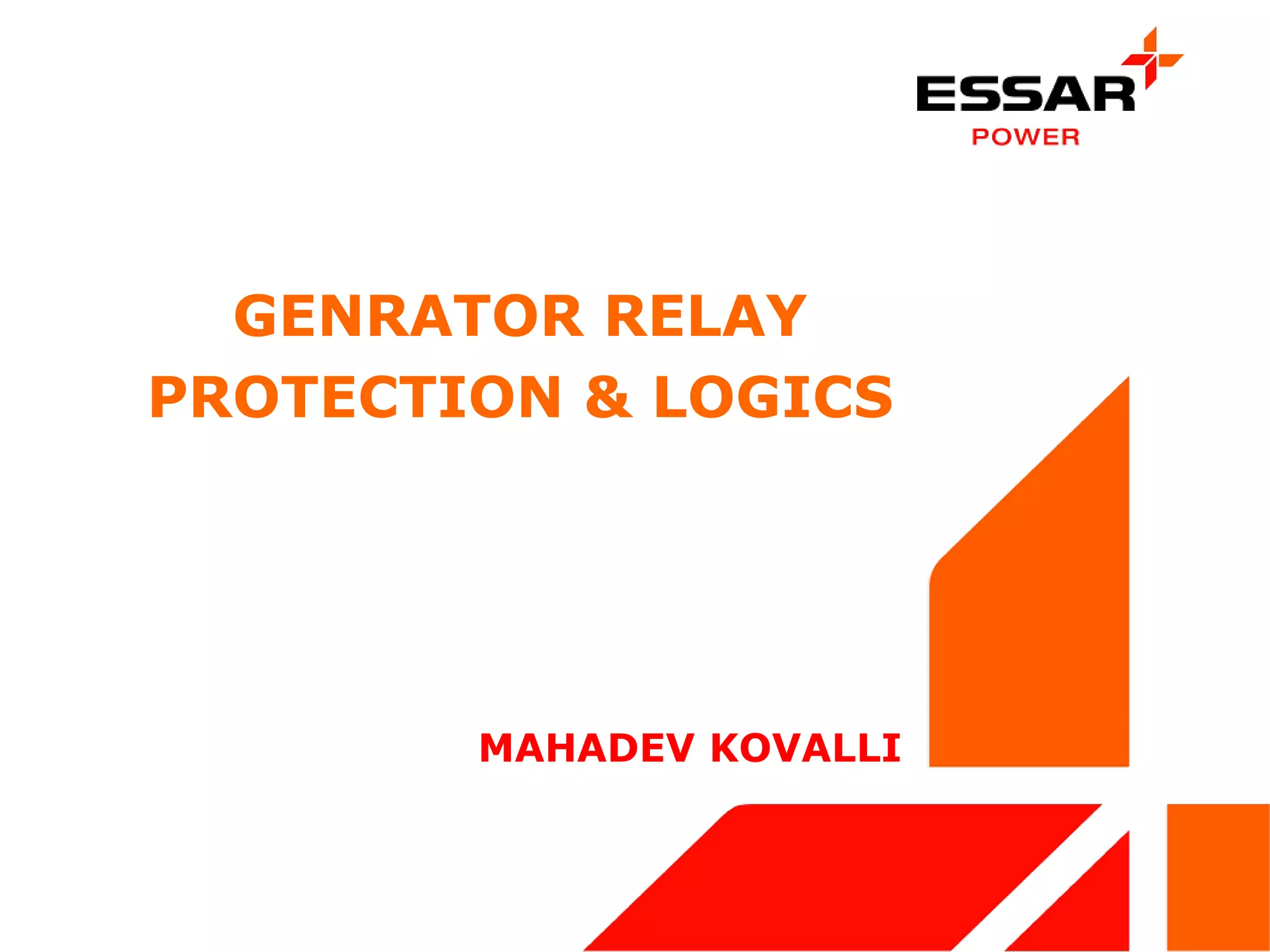
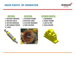
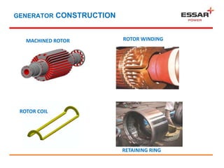
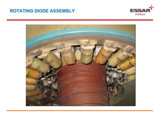
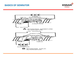
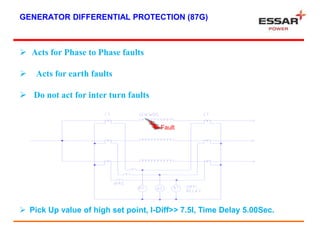
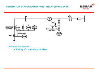
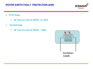
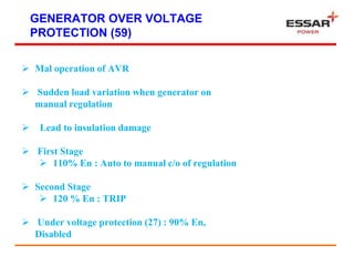
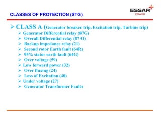
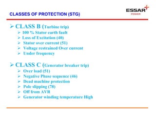
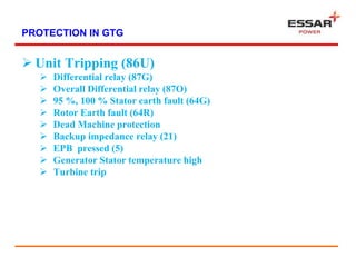
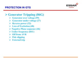
GENRATOR RELAY
PROTECTION & LOGICS
MAHADEV KOVALLI
MAIN PARTS OF GENRATOR
ROTOR: STATOR: OTHER PARTS:
1. ROTOR FORGING 1. STATOR FRAME 1. BEARINGS
2. ROTOR COILS 2.STATOR CORE 2. BASE FRAME
3. ROTOR WEDGES 3. STATOR WINDING 3. AIR FILTER
4. RETAINING RINGS 4. END COVERS 4. ENCLOSURE
5. FANS
GENERATOR CONSTRUCTION
MACHINED ROTOR ROTOR WINDING
ROTOR COIL
RETAINING RING
ROTATING DIODE ASSEMBLY
GENERATION OF POWER
TURBINE
GENERATOR
TRANSFORMER CB
ISOLATOR GRID/
BUS
THE ELECTRICAL MACHINE WHICH CONVERTS MECHANICAL ENERGY INTO
ELECTRICAL ENERGY WHICH IS AN ALTERNATING CURRENT (AC) IN NATURE
IS CALLED AS AN AC GENERATOR OR ALTERNATOR.
BASICS OF GENRATOR
PRINCIPLE:
ALL ELECTRICAL GENERATORS, WHETHER DC OR AC, DEPEND UPON THE PRINCIPLE
OF ELECTROMAGNETIC INDUCTION. AN EMF IS INDUCED IN A COIL AS A RESULT OF
A COIL CUTTING THROUGH A MAGNETIC FIELD, OR A MAGNETIC FIELD CUTTING
THROUGH A COIL. AS LONG AS THERE IS RELATIVE MOTION BETWEEN A
CONDUCTOR AND A MAGNETIC FIELD, A VOLTAGE WILL BE INDUCED IN THE
CONDUCTOR.
THAT PART OF A GENERATOR THAT PRODUCES THE MAGNETIC FIELD IS CALLED THE
FIELD. THAT PART IN WHICH THE VOLTAGE IS INDUCED IS CALLED THE ARMATURE.
FOR RELATIVE MOTION TO TAKE PLACE BETWEEN THE CONDUCTOR AND THE
MAGNETIC FIELD, ALL GENERATORS MUST HAVE TWO MECHANICAL PARTS — A
ROTOR AND A STATOR.
BASICS OF GENRATOR
Protection System
 Generator must be protected from electrical faults,
mechanical problem and adverse system conditions
 Some fault require immediate attention (shutdown) while
others just require alarming or transfer to redundant
controllers
 Avoid outage of time
 Cost
FAULTS IN GENRATOR
Electrical Faults
 Phase to Phase Faults
 Inter turn faults
 Stator Earth fault
 Rotor Earth faults
FAULTS IN GENRATOR
SYSTEM FAULTS
 Over Voltage
 Under Voltage
 Over Frequency
 Over loading
 Unbalanced loading
 Reverse power
 Loss of Excitation
 Under Frequency
FAULTS IN GENERATOR
 Mechanical Defects
 Bearing temperature
 Vibration
 Prime mover failure
 Winding temperature
 Lube oil problems
Primary protection
 Generator Differential protection (87G)
 Stator earth fault Protection (59N)
 95 % winding
 100 % winding
 Rotor Earth fault (64R)
 First Rotor earth fault
 Second rotor earth fault
 Loss of Excitation (40)
GENERATOR DIFFERENTIAL PROTECTION (87G)
 Acts for Phase to Phase faults
 Acts for earth faults
 Do not act for inter turn faults
Fault
 Pick Up value of high set point, I-Diff>> 7.5I, Time Delay 5.00Sec.
GENERATOR STATOR EARTH FAULT RELAY (59 N & 27-3N)
• Acts for any Earth fault in
 Stator
 Potential transformers
 Lightening Arrestors
 Bus ducts
 Generator Transformer 11
KV side
GENERATOR STATOR EARTH FAULT RELAY (59 N & 27-3N)
Stator Earth fault
 Pickup 6V, time delay 0.50Sec
ROTOR EARTH FAULT PROTECTION (64R)
 First Stage
 IR Value less than K OHMS- ALARM
 Second stage
 IR Value less than K OHMS - TRIP
Excitation
supply
BACKUP PROTECTION
 Negative Phase sequence
 Over current relay with voltage Restraint (51V)
 Distance relay (21)
 Over excitation protection
NEGATIVE PHASE SEQUENCE (46G)
 One open phase of the line
 One open pole of the circuit breaker
 Unbalanced faults
 Stator winding faults
 Single phase Traction loads
 Single Phase Arc furnaces
 Continuously Permissible Current
I2>12.3%, Time delay 10.00Sec-
Alaram.
Pick Up value,I2>> 60%,Time delay
3.00Sec-Trip.
OVER CURRENT RELAY WITH VOLTAGE
RESTRAINT (51V)
 Heavy over loads
 Short circuits
 Dip in Grid voltage
 Failure of voltage regulator
 Setting: 105% IN
 Standard inverse characteristics
REVERSE POWER (32)
 Prime mover failure (inadvertent closure of steam control valves)
 Protection against motoring
 Over heating of turbine low pressure blades
 P> Reverse power pickup - -2.43% of the rated power for 5 sec.
DISTANCE PROTECTION (21)
 Back up protection
 Co-ordination with other relays
 Impedance below 70% of generator
LOSS OF EXCITATION (40 G)
 Open field winding
 Malfunction of AVR
 Generator will operate as a
induction generator
 Heats up rotor
 May create instability
OVER FLUXING (24)
 Voltage / frequency
 Core saturation in transformer
 Stage 1 : 115%
 Stage 2 : 120%
UNDER /OVER FREQUENCY (81)
 Load rejection / tripping of transmission lines
 Turbine problem
 System over load
 Over frequency will lead to over speeding
 Under frequency will damage low pressure
stages
 Stage 1 : 48.5 Hz and 51.5 Hz - Alarm
 Stage 2 : 47.5 Hz and 52.5 Hz - Trip
GENERATOR OVER VOLTAGE
PROTECTION (59)
 Mal operation of AVR
 Sudden load variation when generator on
manual regulation
 Lead to insulation damage
 First Stage
 110% En : Auto to manual c/o of regulation
 Second Stage
 120 % En : TRIP
 Under voltage protection (27) : 90% En,
Disabled
CLASSES OF PROTECTION (STG)
 CLASS A (Generator breaker trip, Excitation trip, Turbine trip)
 Generator Differential relay (87G)
 Overall Differential relay (87 O)
 Backup impedance relay (21)
 Second rotor Earth fault (64R)
 95% stator earth fault (64G)
 Over voltage (59)
 Low forward power (32)
 Over fluxing (24)
 Loss of Excitation (40)
 Under voltage (27)
 Generator Transformer Faults
CLASSES OF PROTECTION (STG)
 CLASS B (Turbine trip)
 100 % Stator earth fault
 Loss of Excitation (40)
 Stator over current (51)
 Voltage restrained Over current
 Under frequency
 CLASS C (Generator breaker trip)
 Over load (51)
 Negative Phase sequence (46)
 Dead machine protection
 Pole slipping (78)
 Off from AVR
 Generator winding temperature High
PROTECTION IN GTG
 Unit Tripping (86U)
 Differential relay (87G)
 Overall Differential relay (87O)
 95 %, 100 % Stator earth fault (64G)
 Rotor Earth fault (64R)
 Dead Machine protection
 Backup impedance relay (21)
 EPB pressed (5)
 Generator Stator temperature high
 Turbine trip
PROTECTION IN GTG
 Generator Tripping (86G)
 Generator over voltage (59)
 Generator under voltage (27)
 Reverse power (32)
 Loss of Excitation (40)
 Negative Phase sequence (46)
 Under frequency (81U)
 Off from AVR
 Pole slipping
 External trip
RFERENCES
THANK YOU

Genrator Relay Protection & Logics

  • 1.
    GENRATOR RELAY PROTECTION &LOGICS MAHADEV KOVALLI
  • 2.
    MAIN PARTS OFGENRATOR ROTOR: STATOR: OTHER PARTS: 1. ROTOR FORGING 1. STATOR FRAME 1. BEARINGS 2. ROTOR COILS 2.STATOR CORE 2. BASE FRAME 3. ROTOR WEDGES 3. STATOR WINDING 3. AIR FILTER 4. RETAINING RINGS 4. END COVERS 4. ENCLOSURE 5. FANS
  • 3.
    GENERATOR CONSTRUCTION MACHINED ROTORROTOR WINDING ROTOR COIL RETAINING RING
  • 4.
  • 5.
    GENERATION OF POWER TURBINE GENERATOR TRANSFORMERCB ISOLATOR GRID/ BUS THE ELECTRICAL MACHINE WHICH CONVERTS MECHANICAL ENERGY INTO ELECTRICAL ENERGY WHICH IS AN ALTERNATING CURRENT (AC) IN NATURE IS CALLED AS AN AC GENERATOR OR ALTERNATOR.
  • 6.
    BASICS OF GENRATOR PRINCIPLE: ALLELECTRICAL GENERATORS, WHETHER DC OR AC, DEPEND UPON THE PRINCIPLE OF ELECTROMAGNETIC INDUCTION. AN EMF IS INDUCED IN A COIL AS A RESULT OF A COIL CUTTING THROUGH A MAGNETIC FIELD, OR A MAGNETIC FIELD CUTTING THROUGH A COIL. AS LONG AS THERE IS RELATIVE MOTION BETWEEN A CONDUCTOR AND A MAGNETIC FIELD, A VOLTAGE WILL BE INDUCED IN THE CONDUCTOR. THAT PART OF A GENERATOR THAT PRODUCES THE MAGNETIC FIELD IS CALLED THE FIELD. THAT PART IN WHICH THE VOLTAGE IS INDUCED IS CALLED THE ARMATURE. FOR RELATIVE MOTION TO TAKE PLACE BETWEEN THE CONDUCTOR AND THE MAGNETIC FIELD, ALL GENERATORS MUST HAVE TWO MECHANICAL PARTS — A ROTOR AND A STATOR.
  • 7.
  • 8.
    Protection System  Generatormust be protected from electrical faults, mechanical problem and adverse system conditions  Some fault require immediate attention (shutdown) while others just require alarming or transfer to redundant controllers  Avoid outage of time  Cost
  • 9.
    FAULTS IN GENRATOR ElectricalFaults  Phase to Phase Faults  Inter turn faults  Stator Earth fault  Rotor Earth faults
  • 10.
    FAULTS IN GENRATOR SYSTEMFAULTS  Over Voltage  Under Voltage  Over Frequency  Over loading  Unbalanced loading  Reverse power  Loss of Excitation  Under Frequency
  • 11.
    FAULTS IN GENERATOR Mechanical Defects  Bearing temperature  Vibration  Prime mover failure  Winding temperature  Lube oil problems
  • 12.
    Primary protection  GeneratorDifferential protection (87G)  Stator earth fault Protection (59N)  95 % winding  100 % winding  Rotor Earth fault (64R)  First Rotor earth fault  Second rotor earth fault  Loss of Excitation (40)
  • 13.
    GENERATOR DIFFERENTIAL PROTECTION(87G)  Acts for Phase to Phase faults  Acts for earth faults  Do not act for inter turn faults Fault  Pick Up value of high set point, I-Diff>> 7.5I, Time Delay 5.00Sec.
  • 14.
    GENERATOR STATOR EARTHFAULT RELAY (59 N & 27-3N) • Acts for any Earth fault in  Stator  Potential transformers  Lightening Arrestors  Bus ducts  Generator Transformer 11 KV side
  • 15.
    GENERATOR STATOR EARTHFAULT RELAY (59 N & 27-3N) Stator Earth fault  Pickup 6V, time delay 0.50Sec
  • 16.
    ROTOR EARTH FAULTPROTECTION (64R)  First Stage  IR Value less than K OHMS- ALARM  Second stage  IR Value less than K OHMS - TRIP Excitation supply
  • 17.
    BACKUP PROTECTION  NegativePhase sequence  Over current relay with voltage Restraint (51V)  Distance relay (21)  Over excitation protection
  • 18.
    NEGATIVE PHASE SEQUENCE(46G)  One open phase of the line  One open pole of the circuit breaker  Unbalanced faults  Stator winding faults  Single phase Traction loads  Single Phase Arc furnaces  Continuously Permissible Current I2>12.3%, Time delay 10.00Sec- Alaram. Pick Up value,I2>> 60%,Time delay 3.00Sec-Trip.
  • 19.
    OVER CURRENT RELAYWITH VOLTAGE RESTRAINT (51V)  Heavy over loads  Short circuits  Dip in Grid voltage  Failure of voltage regulator  Setting: 105% IN  Standard inverse characteristics
  • 20.
    REVERSE POWER (32) Prime mover failure (inadvertent closure of steam control valves)  Protection against motoring  Over heating of turbine low pressure blades  P> Reverse power pickup - -2.43% of the rated power for 5 sec.
  • 21.
    DISTANCE PROTECTION (21) Back up protection  Co-ordination with other relays  Impedance below 70% of generator
  • 22.
    LOSS OF EXCITATION(40 G)  Open field winding  Malfunction of AVR  Generator will operate as a induction generator  Heats up rotor  May create instability
  • 23.
    OVER FLUXING (24) Voltage / frequency  Core saturation in transformer  Stage 1 : 115%  Stage 2 : 120%
  • 24.
    UNDER /OVER FREQUENCY(81)  Load rejection / tripping of transmission lines  Turbine problem  System over load  Over frequency will lead to over speeding  Under frequency will damage low pressure stages  Stage 1 : 48.5 Hz and 51.5 Hz - Alarm  Stage 2 : 47.5 Hz and 52.5 Hz - Trip
  • 25.
    GENERATOR OVER VOLTAGE PROTECTION(59)  Mal operation of AVR  Sudden load variation when generator on manual regulation  Lead to insulation damage  First Stage  110% En : Auto to manual c/o of regulation  Second Stage  120 % En : TRIP  Under voltage protection (27) : 90% En, Disabled
  • 27.
    CLASSES OF PROTECTION(STG)  CLASS A (Generator breaker trip, Excitation trip, Turbine trip)  Generator Differential relay (87G)  Overall Differential relay (87 O)  Backup impedance relay (21)  Second rotor Earth fault (64R)  95% stator earth fault (64G)  Over voltage (59)  Low forward power (32)  Over fluxing (24)  Loss of Excitation (40)  Under voltage (27)  Generator Transformer Faults
  • 28.
    CLASSES OF PROTECTION(STG)  CLASS B (Turbine trip)  100 % Stator earth fault  Loss of Excitation (40)  Stator over current (51)  Voltage restrained Over current  Under frequency  CLASS C (Generator breaker trip)  Over load (51)  Negative Phase sequence (46)  Dead machine protection  Pole slipping (78)  Off from AVR  Generator winding temperature High
  • 29.
    PROTECTION IN GTG Unit Tripping (86U)  Differential relay (87G)  Overall Differential relay (87O)  95 %, 100 % Stator earth fault (64G)  Rotor Earth fault (64R)  Dead Machine protection  Backup impedance relay (21)  EPB pressed (5)  Generator Stator temperature high  Turbine trip
  • 30.
    PROTECTION IN GTG Generator Tripping (86G)  Generator over voltage (59)  Generator under voltage (27)  Reverse power (32)  Loss of Excitation (40)  Negative Phase sequence (46)  Under frequency (81U)  Off from AVR  Pole slipping  External trip
  • 31.
  • 32.