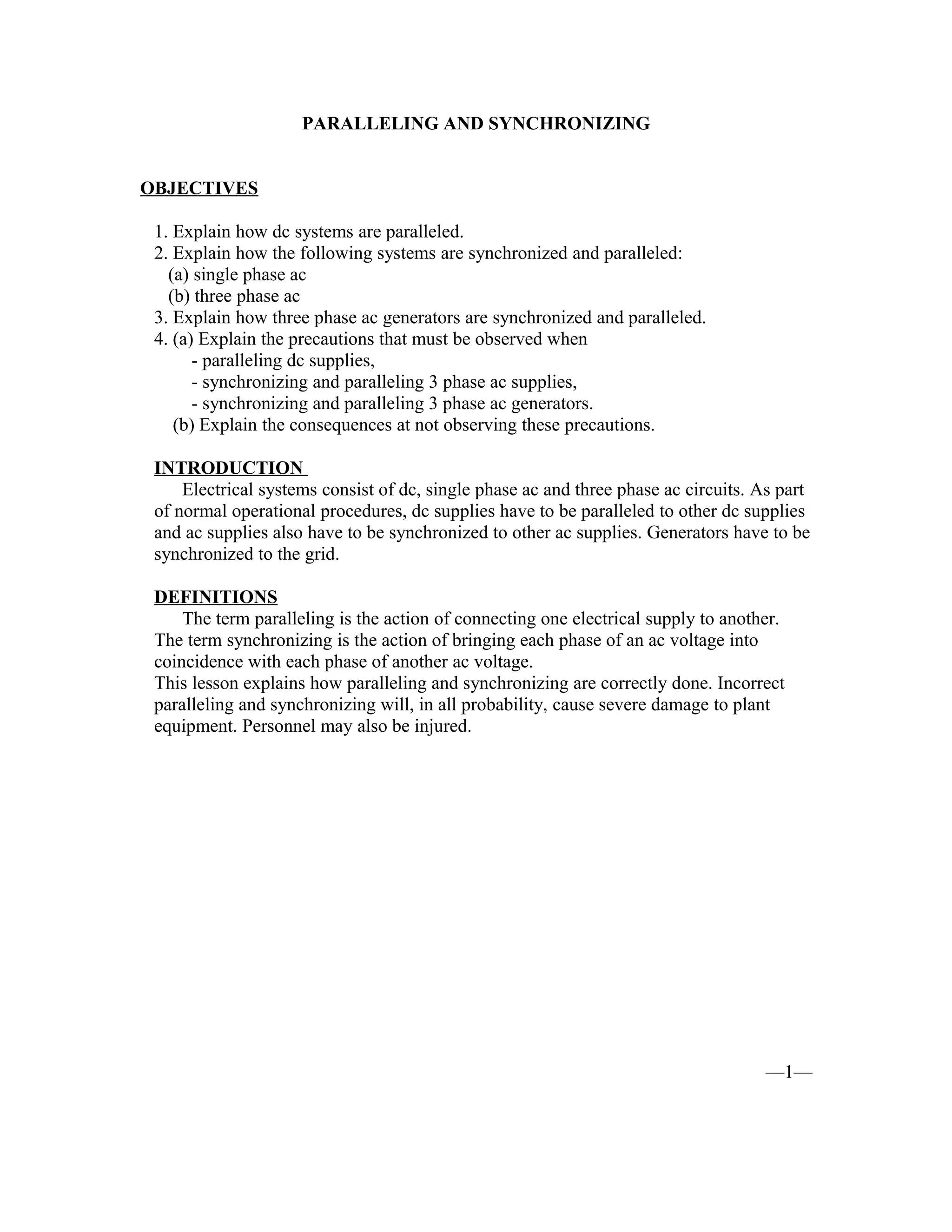
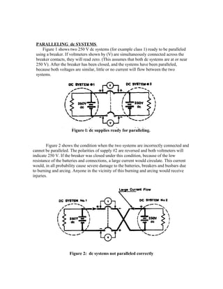
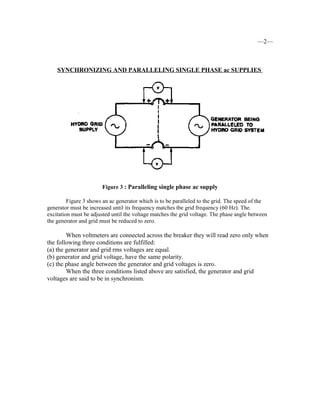
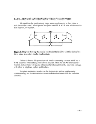
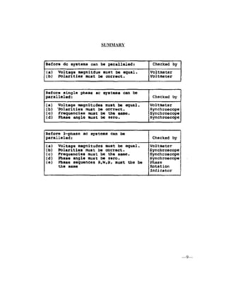
PARALLELING AND SYNCHRONIZING
OBJECTIVES
1. Explain how dc systems are paralleled.
2. Explain how the following systems are synchronized and paralleled:
(a) single phase ac
(b) three phase ac
3. Explain how three phase ac generators are synchronized and paralleled.
4. (a) Explain the precautions that must be observed when
- paralleling dc supplies,
- synchronizing and paralleling 3 phase ac supplies,
- synchronizing and paralleling 3 phase ac generators.
(b) Explain the consequences at not observing these precautions.
INTRODUCTION
Electrical systems consist of dc, single phase ac and three phase ac circuits. As part
of normal operational procedures, dc supplies have to be paralleled to other dc supplies
and ac supplies also have to be synchronized to other ac supplies. Generators have to be
synchronized to the grid.
DEFINITIONS
The term paralleling is the action of connecting one electrical supply to another.
The term synchronizing is the action of bringing each phase of an ac voltage into
coincidence with each phase of another ac voltage.
This lesson explains how paralleling and synchronizing are correctly done. Incorrect
paralleling and synchronizing will, in all probability, cause severe damage to plant
equipment. Personnel may also be injured.
—1—
PARALLELING dc SYSTEMS
Figure 1 shows two 250 V dc systems (for example class 1) ready to be paralleled
using a breaker. If voltmeters shown by (V) are simultaneously connected across the
breaker contacts, they will read zero. (This assumes that both dc systems are at or near
250 V). After the breaker has been closed, and the systems have been paralleled,
because both voltages are similar, little or no current will flow between the two
systems.
Figure l: dc supplies ready for paralleling.
Figure 2 shows the condition when the two systems are incorrectly connected and
cannot be paralleled. The polarities of supply #2 are reversed and both voltmeters will
indicate 250 V. If the breaker was closed under this condition, because of the low
resistance of the batteries and connections, a large current would circulate. This current
would, in all probability cause severe damage to the batteries, breakers and busbars due
to burning and arcing. Anyone in the vicinity of this burning and arcing would receive
injuries.
Figure 2: dc systems not paralleled correctly
—2—
SYNCHRONIZING AND PARALLELING SINGLE PHASE ac SUPPLIES
Figure 3 : Paralleling single phase ac supply
Figure 3 shows an ac generator which is to be paralleled to the grid. The speed of the
generator must be increased until its frequency matches tbe grid frequency (60 Hz). The.
excitation must be adjusted until the voltage matches the grid voltage. The phase angle between
the generator and grid must be reduced to zero.
When voltmeters are connected across the breaker they will read zero only when
the following three conditions are fulfilled:
(a) the generator and grid rms voltages are equal.
(b) generator and grid voltage, have the same polarity.
(c) the phase angle between the generator and grid voltages is zero.
When the three conditions listed above are satisfied, the generator and grid
voltages are said to be in synchronism.
—3—
If the phase angle is not zero, see Figures 4(a) and 4(b), a voltage will exist across
the breaker. Figure 5 shows the phasors of supply and generator voltages when the
generator voltage is lagging by 45°. The dashed phasor indicates the voltage across the
breaker.
Figure 4(a) Figure 4(b)
Voltage waveforms out of phase by 45°
Figure 5: Phasor diagram showing voltages 45° out of phase.
—4—
Before the breaker can be closed, the waveforms must be brought into phase, see
Figures 6(a) and 6(b). When the waveforms are in phase, there will be no voltage
difference across the breaker and the breaker can be safely closed. The generator will be
paralleled to the grid.
Figure 6(a) Figure 6(b)
Diagrams showing voltage waveforms and voltage phasors for two equal voltages
which are in phase.
The Synchroscope
The synchroscope, Figure 7 gives a more accurate indication of synchronism than
a voltmeter connected across the breaker contacts. The position of the pointer indicates
the difference in phase angle. If there is a small difference in frequency (up to 2 Hz) the
pointer will rotate. With larger frequency differences, the synchroscope is designed not to
rotate. The pointer will rotate in the SLOW direction when the generator frequency is
below system frequency. The pointer will rotate in the FAST direction if the generator
frequency is greater than system frequency. When the pointer indicates zero degrees
phase angle difference, (at the 12 o’clock position) (see Figure 6) and the pointer is
steady, the voltages are in phase and the frequencies of the generator and system are
equal.
—5—
It is vitally important to check the operation of the synchroscope before each
synchronizing is attempted. To do this, the generator is operated at less than synchronous
speed, and the synchroscope must rotate in the SLOW direction, Similarly, when the
generator is operated at a speed greater than synchronous, the synchroscope must rotate
in the FAST direction.
Voltmeters are used to measure the rms voltages of the grid and generator. When
the generator and grid voltages are equal and the synchroscope is steady at the zero
degrees position, the breaker can be closed to parallel the generator to the grid.
Figure 7:
Checking phase angle and frequency using a synchroscope. Voltmeters used for
checking rms voltage magnitudes.
—6—
Synchronizing Out of Phase
If the circuit breaker is closed when the synchrosoope does not indicate zero
degrees, the breaker will be joining together the generator which is out of phase with the
system.
Figure 8: Magnetic forces produced when generator breaker is closed out of phase.
This effect takes place the instant the breaker is closed and due to the accelerating
effect on the rotor, places an immense mechanical torque on the rotor and turbine shafts.
The generator windings and connections are subjected to enormous currents and
magnetic forces. Depending on the phase angle when the breaker is closed, the forces
may be sufficient to permanently distort the generator windings and break the turbine to
generator coupling bolts. On some occasions, the generator transformer has been severely
damaged. This is due to enormous currents and magnetic forces occurring in the
transformer.
—7—
.
PARALLELING OR SYNCHRONIZING THREE PHASE SUPPLIES
All conditions for synchronizing single phase supplies apply to three phase as
well. In addition, with 3 phase systems, the phase rotation, R, W, B, must be observed for
both supplies, see Figure 9.
Figure 9: Diagram showing the phasor conditions that must be satisfied before two
three phase generators can be synchronized.
Failure to observe this precaution will involve connecting a system which has a
RWB clockwise rotation being connected to a system which has a RWB anticlockwise
rotation. Both systems will try and rotate in different directions at the sane time. Damage
will follow to windings, busbars and breakers.
The phase sequences, are checked for the generator and the supply during
commissioning, and if correct need not be rechecked unless connections are altered or
disturbed.
—8—
SUMMARY
—9—
(4) synch

(4) synch

  • 1.
    PARALLELING AND SYNCHRONIZING OBJECTIVES 1.Explain how dc systems are paralleled. 2. Explain how the following systems are synchronized and paralleled: (a) single phase ac (b) three phase ac 3. Explain how three phase ac generators are synchronized and paralleled. 4. (a) Explain the precautions that must be observed when - paralleling dc supplies, - synchronizing and paralleling 3 phase ac supplies, - synchronizing and paralleling 3 phase ac generators. (b) Explain the consequences at not observing these precautions. INTRODUCTION Electrical systems consist of dc, single phase ac and three phase ac circuits. As part of normal operational procedures, dc supplies have to be paralleled to other dc supplies and ac supplies also have to be synchronized to other ac supplies. Generators have to be synchronized to the grid. DEFINITIONS The term paralleling is the action of connecting one electrical supply to another. The term synchronizing is the action of bringing each phase of an ac voltage into coincidence with each phase of another ac voltage. This lesson explains how paralleling and synchronizing are correctly done. Incorrect paralleling and synchronizing will, in all probability, cause severe damage to plant equipment. Personnel may also be injured. —1—
  • 2.
    PARALLELING dc SYSTEMS Figure1 shows two 250 V dc systems (for example class 1) ready to be paralleled using a breaker. If voltmeters shown by (V) are simultaneously connected across the breaker contacts, they will read zero. (This assumes that both dc systems are at or near 250 V). After the breaker has been closed, and the systems have been paralleled, because both voltages are similar, little or no current will flow between the two systems. Figure l: dc supplies ready for paralleling. Figure 2 shows the condition when the two systems are incorrectly connected and cannot be paralleled. The polarities of supply #2 are reversed and both voltmeters will indicate 250 V. If the breaker was closed under this condition, because of the low resistance of the batteries and connections, a large current would circulate. This current would, in all probability cause severe damage to the batteries, breakers and busbars due to burning and arcing. Anyone in the vicinity of this burning and arcing would receive injuries. Figure 2: dc systems not paralleled correctly
  • 3.
    —2— SYNCHRONIZING AND PARALLELINGSINGLE PHASE ac SUPPLIES Figure 3 : Paralleling single phase ac supply Figure 3 shows an ac generator which is to be paralleled to the grid. The speed of the generator must be increased until its frequency matches tbe grid frequency (60 Hz). The. excitation must be adjusted until the voltage matches the grid voltage. The phase angle between the generator and grid must be reduced to zero. When voltmeters are connected across the breaker they will read zero only when the following three conditions are fulfilled: (a) the generator and grid rms voltages are equal. (b) generator and grid voltage, have the same polarity. (c) the phase angle between the generator and grid voltages is zero. When the three conditions listed above are satisfied, the generator and grid voltages are said to be in synchronism.
  • 4.
  • 5.
    If the phaseangle is not zero, see Figures 4(a) and 4(b), a voltage will exist across the breaker. Figure 5 shows the phasors of supply and generator voltages when the generator voltage is lagging by 45°. The dashed phasor indicates the voltage across the breaker. Figure 4(a) Figure 4(b) Voltage waveforms out of phase by 45° Figure 5: Phasor diagram showing voltages 45° out of phase.
  • 6.
  • 7.
    Before the breakercan be closed, the waveforms must be brought into phase, see Figures 6(a) and 6(b). When the waveforms are in phase, there will be no voltage difference across the breaker and the breaker can be safely closed. The generator will be paralleled to the grid. Figure 6(a) Figure 6(b) Diagrams showing voltage waveforms and voltage phasors for two equal voltages which are in phase. The Synchroscope The synchroscope, Figure 7 gives a more accurate indication of synchronism than a voltmeter connected across the breaker contacts. The position of the pointer indicates the difference in phase angle. If there is a small difference in frequency (up to 2 Hz) the pointer will rotate. With larger frequency differences, the synchroscope is designed not to rotate. The pointer will rotate in the SLOW direction when the generator frequency is below system frequency. The pointer will rotate in the FAST direction if the generator frequency is greater than system frequency. When the pointer indicates zero degrees phase angle difference, (at the 12 o’clock position) (see Figure 6) and the pointer is steady, the voltages are in phase and the frequencies of the generator and system are equal.
  • 8.
  • 9.
    It is vitallyimportant to check the operation of the synchroscope before each synchronizing is attempted. To do this, the generator is operated at less than synchronous speed, and the synchroscope must rotate in the SLOW direction, Similarly, when the generator is operated at a speed greater than synchronous, the synchroscope must rotate in the FAST direction. Voltmeters are used to measure the rms voltages of the grid and generator. When the generator and grid voltages are equal and the synchroscope is steady at the zero degrees position, the breaker can be closed to parallel the generator to the grid. Figure 7: Checking phase angle and frequency using a synchroscope. Voltmeters used for checking rms voltage magnitudes. —6—
  • 10.
    Synchronizing Out ofPhase If the circuit breaker is closed when the synchrosoope does not indicate zero degrees, the breaker will be joining together the generator which is out of phase with the system. Figure 8: Magnetic forces produced when generator breaker is closed out of phase. This effect takes place the instant the breaker is closed and due to the accelerating effect on the rotor, places an immense mechanical torque on the rotor and turbine shafts. The generator windings and connections are subjected to enormous currents and magnetic forces. Depending on the phase angle when the breaker is closed, the forces may be sufficient to permanently distort the generator windings and break the turbine to generator coupling bolts. On some occasions, the generator transformer has been severely damaged. This is due to enormous currents and magnetic forces occurring in the transformer. —7—
  • 11.
    . PARALLELING OR SYNCHRONIZINGTHREE PHASE SUPPLIES All conditions for synchronizing single phase supplies apply to three phase as well. In addition, with 3 phase systems, the phase rotation, R, W, B, must be observed for both supplies, see Figure 9. Figure 9: Diagram showing the phasor conditions that must be satisfied before two three phase generators can be synchronized. Failure to observe this precaution will involve connecting a system which has a RWB clockwise rotation being connected to a system which has a RWB anticlockwise rotation. Both systems will try and rotate in different directions at the sane time. Damage will follow to windings, busbars and breakers. The phase sequences, are checked for the generator and the supply during commissioning, and if correct need not be rechecked unless connections are altered or disturbed. —8—
  • 12.