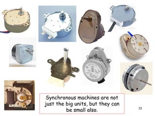
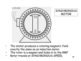
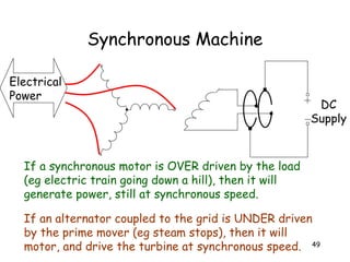
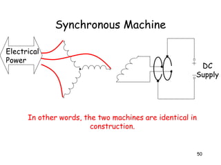
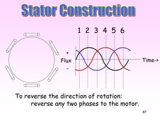
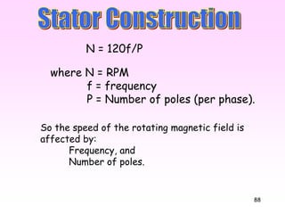
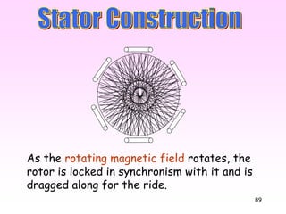
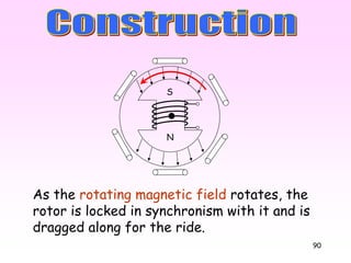
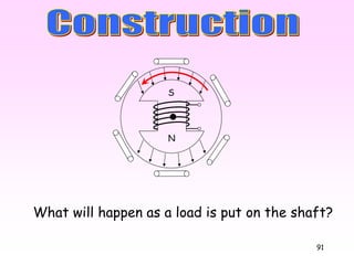
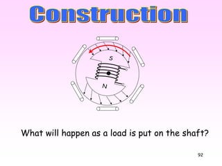
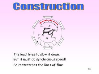
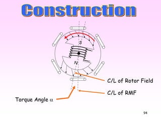
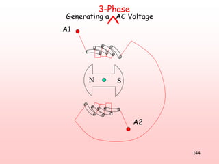
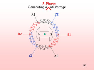
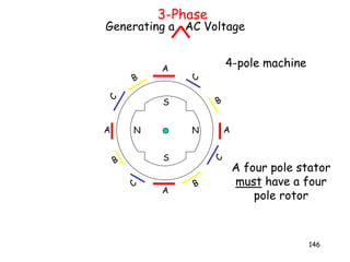
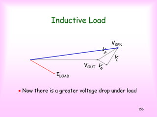
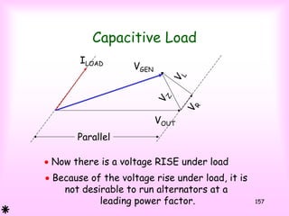
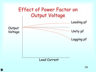
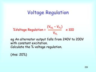
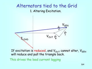
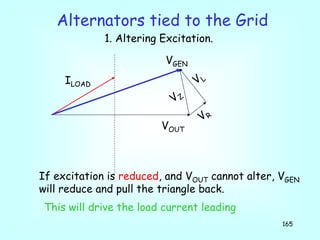
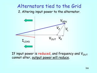
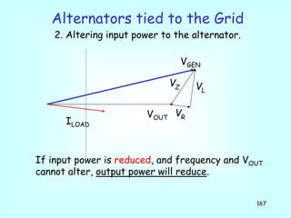
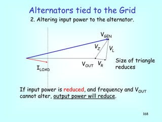
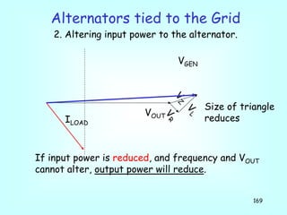
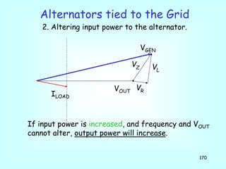
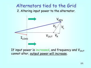
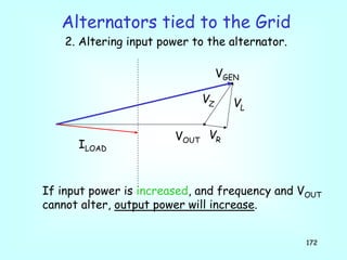
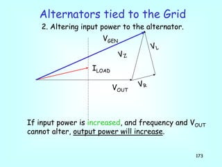
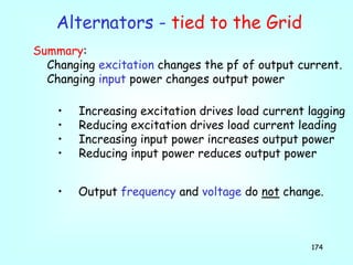
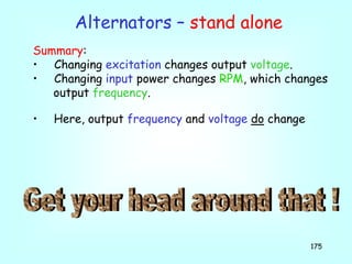
1
2
Classroom Rules:
1. I talk, you listen
2. I don’t allow:
A. Heads on desk
B. Feet on desk
C. Going to sleep in class
D. MP3 players
3. Mobile phones are to be off, or on “silent” unless
OK’d with me, and in you bag (not on desk)
4. Should they be OK’d, and you receive a call, you
will answer it outside the classroom
5. No SMS-ing in class
6. Keith Butler’s number is: 0417 637 909
3
Topics (from Learning Outcomes)
10. Three-phase synchronous machines
• operating principles
• construction feature
• application
11. Three-phase synchronous machines
• effects of load changes
• effects of excitation change
• load/current characteristics
12. Single phase synchronous machines
• alternators
• motors
• applications
4
Assessment
(a)All prac’s must be completed
• A final written exam will be given on the
learning outcomes covered. Should a
student fail, they will be allowed one
further attempt during block. Should
they fail this they will be allowed one
further attempt within six weeks of
completing the block. Should they fail this
they will be in a “Show Cause” situation.
5
6500 KW Genset / Generator Set, powered with a Cummins VTA28G1 Engine
7
8
9
2 x 14MW Synchronous Motors
…apparently, they use permanent magnets!
10
11
3 phase Dunlite machine
12
13
Synchronous machines are not
just the big units, but they can
be small also.
14
15
V
AC Supply R
V
I
I
Current is in phase
with voltage.
Time->
16
LAC supply
V
I V
I
Current lags the
Voltage by 90o
17
CAC Supply
But if an ammeter were placed in series it would
most definitely read a current.
Current appears to pass through the capacitor.
In reality, it is charging in one direction, and then
discharging and recharging in the other direction.
18
V
I
CAC Supply
V
I
Current leads the
Voltage by 90o
19
This opposition to current flow is called:
Inductive reactance, in inductors. (XL)
Capacitive reactance in capacitors. (XC)
Both Inductors and Capacitors oppose, or “resist”
current flow when connected to AC supplies.
While it opposes current flow, it is NOT called resistance.
Current flow through resistance produces HEAT.
Current flow in inductors and capacitors doesn’t!
20
21
Generator / Transformer / Motor
S F
S
F
S
F S F
S F
S F
B
A
C
AC
B
22
AC
B
Motor
Why isn’t a neutral run to a balanced
three phase Star connected load?
A
B
C
N
?????
23
AC
B
Motor
Because the Star point is at 0V
A
B
C
0V0VN
And the neutral is at zero volts also.
So if they were joined no current would flow.
0A
So why join it?
24
AC
B
Motor
A
B
C
The neutral is not connected to a balanced
three phase star connected load.
Only connected to unbalanced loads!!!
25
Transformer
S F
B
S F
C
Generator / Transformer / Motor
A
B C
F
S F
S
FS
S F
A
26
Transformer
SF
B
SF
C
Generator / Transformer / Motor
A
B C
S
F S
F
SF
SF
A
Swapped
27
3-phase Transformer Secondary
S F
B C
S F
A
S F
A B C
Note that all windings are connected in series, with the two
ends joined together.
28
If we did that with three batteries, there would be major
problems!
29
The voltmeter should read the sum of the three voltages?
Right?
VA
VB
VC
A
C B
F
S F
S
FS
Transformer
V
The voltmeter reads the phasor sum of the voltages.
30
The voltmeter reads, in effect, the distance between the
beginning of VA and the end of VC. ie. 0V
VA
VB
VC
A
C B
F
S F
S
FS
Transformer
V
We can connect the two ends together because the
phasor sum adds up to zero!
31
Transformer
VA
VB
VC
A
C B
F
S F
S
FS
The voltmeter reads, in effect, the distance between the
beginning of VA and the end of VC. ie. 0V
We can connect the two ends together because the
phasor sum adds up to zero!
No Arc!
32
33
Generator Load
STAR
VL = √3 VPH
IL = IPH
DELTA
IL = √3 IPH
VL = VPH
P = 3 x VPH x IPH x Cosφ
= 3 x VL/√3 x IL x Cosφ
= 3/√3 x VL x IL x Cosφ
= √3 VL x IL x Cosφ
P = 3 x VPH x IPH x Cosφ
= 3 x VLx IL/√3 x Cosφ
= 3/√3 x VL x IL x Cosφ
= √3 VL x IL x Cosφ
34
P = √3 VL x IL x Cosφ
NOT:
P = 415 x I x pf.
35
Three Single Phase Power Equations:
True Power = Watts = V x I x Cosφ
Apparent Power = VA = V x I
Reactive Power = VAR’s = V x I x Sinφ
Power Factor = Cosφ
where Cosφ = Cosine of the angle
between Voltage
and Current
36
VA
Watts
Var’s
φ
Phase angle
between current
and volts
This can be put as a triangle:
VA2 = Watts2 + Var’s2
37
V=240V
Alternators, where the windings are limited by the
current through them, are rated in VA.
To rate them in watts, (ie. watts delivered to the load)
would give no idea of the current through them.
Load 3 = 14.14A at 45º
Load 1 = 10A
Load 2 = 20A at 60º
P = V x I x Cos 45º
= 240 x 14.14 x 0.707
= 2.4kW
P = V x I x Cos 0º
= 240 x 10 x 1
= 2.4kW
P = V x I x Cos 60º
= 240 x 20 x 0.5
= 2.4kW
38
Q What dictates the phase angle of the current
supplied by a single alternator supplying a single load?
V=240V
Load 3 = 14.14A at 45º
Load 1 = 10A
Load 2 = 20A at 60º
P = V x I x Cos 45º
= 240 x 14.14 x 0.707
= 2.4kW
P = V x I x Cos 0º
= 240 x 10 x 1
= 2.4kW
P = V x I x Cos 60º
= 240 x 20 x 0.5
= 2.4kW
A The load
39
V
Al currents here take the same power
Constant power line
40
V
Al currents here take the same power
Higher power
41
V
Al currents here take the same power
Constant power line
42
V
Al currents here take the same power
Lower power
43
44
45
Alternator
Mechanical Energy Electrical Energy
Losses
AlternatorPrime
Mover
- Diesel Engine
- Steam Turbine
- Small petrol engine
Alternator:
Pout
Eff% = x 100
Pin
Alternator:
Pin = Pout + Losses
46
Losses
Synchronous Motor
Mechanical Energy
MSBElectrical Energy
Motor:
Pout
Eff% = x 100
Pin
Motor
Pin = Pout + Losses
Motor Load
47
Synchronous Machine
Stator
- Identically wound
to an induction motor.
- Connected to supply.
Rotor
- Constant DC field
- Connected to supply
via sliprings.
Electrical
Power
DC
Supply
48
• The stator produces a rotating magnetic field
exactly the same as an induction motor.
• The rotor is a magnet and locks in to the RMF
• Rotor travels at SYNCHRONOUS SPEED.
SYNCHRONOUS
MOTOR
49
Synchronous Machine
If a synchronous motor is OVER driven by the load
(eg electric train going down a hill), then it will
generate power, still at synchronous speed.
If an alternator coupled to the grid is UNDER driven
by the prime mover (eg steam stops), then it will
motor, and drive the turbine at synchronous speed.
Electrical
Power
DC
Supply
50
Synchronous Machine
In other words, the two machines are identical in
construction.
Electrical
Power
DC
Supply
51
52
3000RPM 1500RPM 1000RPM 750RPM
185kw 310A, .88pf 315A, .86pf 343A, .80pf 348A, .78pf
220kw 362A, .89pf 375A, .86pf 408A, .78pf 412A, .78pf
150kw 242A, .90pf 265A, .87pf 279A, .80pf 278A, .77pf
Lower the RPM,
• Larger value IS
• More lagging IS
Characteristic of WEG® Induction Motors.
110kw 182A, .90pf 200A, .84pf 205A, .80pf 203A, .81pf
22kw 39A, .87pf 41A, .83pf 42A, .80pf 47A, .74pf
4kw 7.8A, .87pf 8.2A, .82pf 9A, .74pf 11A, .63pf
What is the
tendency as RPM
gets lower?
53
So why use a Synchronous Motor?
Uses:
– Low Speed Drives. Low speed induction motors
draw very large currents at poor power factors.
This cannot be altered or corrected. In
synchronous motors, the p.f. can be altered to
cause the motor to draw minimum current. (The
alternative is to use a high speed induction
motor through a gearbox.)
– Power Factor Correction
– Constant Speed drives
54
55
56
57
Salient Pole Rotor Cylindrical Rotor
2 basic types:
Cylindrical rotor
Salient Pole
-Low speed
-Diesel Prime Mover
-Hydro systems
-High speed
-Steam Turbine
58
59
60
61
62
63
64
www.tecowestinghouse.com
Small salient pole synchronous machine rotor
65
66
67
68
69
70
71
72
73
74
75
Losses
Synchronous Motor
Mechanical Energy
MSBElectrical Energy
Motor:
Pout
Eff% = x 100
Pin
Motor
Pin = Pout + Losses
Motor Load
76
Same as an induction motor.
77
A1
A2
2-Pole Machine
ie. 3000RPM
78
79
A1
A2
B1B2
C1
C2
2-Pole Machine
ie. 3000RPM
In reality, the coils
span more slots in
a 2-pole motor.
N
S
Notice that for a
two pole stator we
have a 2-pole rotor
80
N N
S
S
A
A
AA
B
B
B
B
C
C
C
C
4-pole machine
A four pole stator
must have a four
pole rotor
81
Flux
+
-
Time->
1
Resultant flux =
1.5 x flux of one phase
N
SN
S
S
N
82
Flux
+
-
Time->
2
Resultant flux =
1.5 x flux of one phase
N
S
N
S
N
S
83
Flux
+
-
Time->
3 4 5 6
84
Flux
+
-
Time->
3 4 5 61 2
So the flux rotates one full rev in one cycle,
for our two pole machine.
85
Flux
+
-
Time->
3 4 5 61 2
Because the flux is a constant value, it gives:
1. Very quiet operation
2. Constant torque as the rotor rotates.
86
Flux
+
-
Time->
3 4 5 61 2
This rotating magnetic field rotates at:
3000RPM for a 2-pole motor
1500RPM for a 4-pole motor
87
Flux
+
-
Time->
3 4 5 61 2
To reverse the direction of rotation:
reverse any two phases to the motor.
88
where N = RPM
f = frequency
P = Number of poles (per phase).
N = 120f/P
So the speed of the rotating magnetic field is
affected by:
Frequency, and
Number of poles.
89
As the rotating magnetic field rotates, the
rotor is locked in synchronism with it and is
dragged along for the ride.
90
N
S
As the rotating magnetic field rotates, the
rotor is locked in synchronism with it and is
dragged along for the ride.
91
What will happen as a load is put on the shaft?
N
S
92
N
S
What will happen as a load is put on the shaft?
93
The load tries to slow it down.
But it must do synchronous speed!
So it stretches the lines of flux.
N
S
94
N
S
C/L of RMF
C/L of Rotor Field
Torque Angle α
95
If the lines stretch to breaking point (ie too
much load), then the rotor stalls
This is referred to as “Pull Out Torque”.
N
S
96
What would the Torque Curve look like?
RPM
Ns0
Torque Curve for an
induction motor
Torque
97
What would the Torque Curve look like?
Torque
RPM
Ns0
Torque “Curve” for a
Synchronous Motor
Pull out
Torque
Zero Torque below
synchronous speed
98
1. Amortisseur winding
Starting a Synchronous Motor?
99
100
Rotor Construction
Squirrel Cage
101
102
103
Starting a Synchronous Motor?
1. Amortisseur winding
This gets the motor up to speed as an
induction motor. When it is close to
synchronous speed it will lock in.
2. Shorting the rotor DC winding and
starting it as a wound rotor motor.
When it is close to synchronous speed,
the short is removed and DC is applied
to the rotor. It will (hopefully) lock
in.
104
3. Using a pony motor to get the
synchronous motor up to speed, then
applying AC to the stator and DC to
the rotor.
(Not applicable if there is a high
starting torque load connected)
Note that these starting methods will only
work if the load on the motor at start can be
reduced or eliminated.
Starting a Synchronous Motor?
105
• Amortisseur windings also reduce hunting.
• Hunting is rhythmic fluctuations of the
RPM around an average value.
• If not subdued, hunting can cause
the rotor to swing out of synchronism.
106
Revs
Time
107
N
S
N
S
N
S
N
S
N
S
And all this while it is whizzing
around at synchronous speed!
108
And all this while it is whizzing
around at synchronous speed!
N
S
109
110
Vsupply
Vinduced
Induced in the
stator from
the rotor
Phasor Diagram of Synchronous Motor
111
Vsupply
Vinduced
Torque angle
α
Isupply
VR
Phasor Diagram of Synchronous Motor
112
Phasor diagram for increased load:
(Excitation current held constant)
Vsupply
Vinduced
α
Isupply
VR
Increased load = Increased Torque Angle
Vinduced
Increasing the load increases the power taken from supply
113
Vsupply
Vinduced
Vinduced
Phasor diagram for increased excitation:
(Constant Load)
α
Constant load = Constant Power line
114
Phasor diagram for increased excitation:
(Constant Load)
Vsupply
Vinduced
α
Constant load = Constant Power line
115
Vsupply
Phasor diagram for increased excitation:
(Constant Load)
Vinduced VR
Isupply
So to force the supply current leading,
we INCREASE excitation
α
Constant load = Constant Power line
116
Vsupply
Vinduced
Isupply
VR
Phasor diagram for decreased excitation:
(Constant Load)
α
Constant load = Constant Power line
117
Vsupply
α
Isupply
VR
Phasor diagram for decreased excitation:
(Constant Load)
Vinduced
So to force the supply current lagging,
we DECREASE excitation
Constant load = Constant Power line
118
Vsupply
Vinduced
Isupply
VR
α
Vsupply
α
I
VR
Vinduced
Vinduced
Isupply
VR
α
Constant load = Constant Power line
Vsupply
119
Vsupply
With a constant load, changing excitation changes
the phase angle and value of supply current.
Isupply
By increasing the DC excitation current to the rotor,
the synchronous motor can act as a capacitor
It can be used for power factor correction.
Constant load = Constant Power line
120
Excitation Current
StatorCurrent
50%
load
Unity pf
Lag Lead
121
Deductions From Vee Curves
• At any particular load there is a certain value of rotor
current which gives a minimum value of stator current and
unity pf.
• If the rotor current is altered either way, the stator
current will increase, and pf will decrease away from 1.
• For any given load there is a certain value of rotor current
below which the rotor will fall out of synchronism.
• For any given load there are two values of rotor current that
will give identical values of stator current. The lower value
gives a lagging pf, and the higher value gives a leading pf.
122
Excitation Current
StatorCurrent
50%
load
Lag
Lead
75%
load
Stability
limit pf=1
123
0.8 pf lag Unity 0.8 pf leadPer unit
Power output
124
125
126
Points:
• At a set load there is a value of excitation that
will give minimum line current.
• Reducing OR increasing excitation from this value
will only increase line current.
• At any other value of line current, there are two
values of excitation current that can produce this.
• If a synchronous motor is heavily loaded, supply
current may not be able to be driven highly
leading.
• If a synchronous motor is lightly loaded, supply
current can be driven highly leading.
127
Single Phase Synchronous Motors
• Used when constant speed is critical, with low
torque requirements. They have low efficiency,
hence made in small sizes.
• Application:
• clocks
• record players
• timers
• recorders
• communications
• servo installations
• Two main types:
• Reluctance motor
• Hysteresis motor
128
Reluctance Motor
Stator
• Stator same as a single phase,
split phase motor.
• Centrifugal Switch operates at
75% synchronous speed to open
circuit the start winding.
Rotor
• Assembled from laminated sheets
with defined teeth cut away. This
forms salient poles.
• Windings are of the squirrel-cage
type.
• Number of rotor poles equals the
number of stator poles.
Two pole, 3000 RPM
rotor
129
Reluctance Motor
• Operation
– Starts as an induction motor, with slip.
– A single phase stator has a “Start” and “Run” winding. At
75% centrifugal the centrifugal switch operates.
– As the load is light there is small slip
– The salient poles become permanently magnetised by the
stator field
– The salient poles will then lock to the stator field.
– Once locked into synchronism the motor will continue to
operate at synchronous speed.
– Not as much power output as a similar physical size 1-phase
motor.
130
Hysteresis Motor
Rotor
• Constructed from hardened steel rings, instead of thin,
magnetically soft, silicon steel laminations.
• “Hysteresis” opposes any change once the flux is created,
so the rotor will lock into the RMF like a permanent magnet.
Stator
• Often a shaded pole stator principle is used.
• If the shaded pole principle is used then the motor is self
starting.
• Magnetic poles are established in the rotor.
• These poles lock to the stator poles.
• The rotor runs at synchronous speed determined by the
poles and frequency.
131
132
Why generate AC?… Why not DC?
DC cant be “transformed” through a transformer.
AC can go through a transformer.
Large brushless DC generators are not possible
Large brushless AC alternators are!
Why do we want to transform it?
It is easier to transmit to distant places
at higher voltages as the current
will be lower. (P=V x I)
Induction motors are simpler and cheaper than
DC motors
133
134
N
S
V
Generating an AC Voltage
135
N S
Generating an AC Voltage
Volts
+
-
Time->
136
NS
Generating an AC Voltage
Volts
+
-
Time->
137
NS
Generating an AC Voltage
Volts
+
-
Time->
138
NS
Generating an AC Voltage
Volts
+
-
Time->
139
N S
Generating an AC Voltage
Volts
+
-
Time->
140
NS
Generating an AC Voltage
Volts
+
-
Time->
141
N
S
V
Generating a AC Voltage
3-Phase
142
N S
Volts
+
-
Time->
Generating a AC Voltage
3-Phase
Require:
Three sets of coils
physically displaced
from each other by
120º electrical.
143
VA
VC
VB
Generating a AC Voltage
3-Phase
N S
144
Generating a AC Voltage
3-Phase
A1
A2
N S
145
Generating a AC Voltage
3-Phase
N S
A1
A2
B1B2
C1
C2
146
N N
S
S
A
A
AA
B
B
B
B
C
C
C
C
4-pole machine
A four pole stator
must have a four
pole rotor
Generating a AC Voltage
3-Phase
147
Alternator
• Reasons for having the three phase winding on the
stator rather than the rotor:
– More space on the stator for the three phase
winding.
– Only one, low voltage winding on the rotor.
• Easier to insulate.
• Less problems with centrifugal force.
– Only two sliprings required rather than four
(3-ph + N)
148
Alternator
Stator
- Connected to load.
Rotor
- Constant DC field
- Connected to its own DC
supply via sliprings.
Electrical
Power
Mechanical
Power
MagneticField
149
Alternator
Q: What keeps an alternator producing 50Hz under all
load conditions?
A: The governor on the prime mover. It detects any
drop in speed, and tries to speed the unit up.
Alternator
Petrol
Engine
150
151
IFIELD
VOUT
Alternator Excitation Curve
(No Load)
152
Alt
LoadR
XL
Internal
Impedance
Alternator
153
VOUTILOAD
VR
VZ VL
VGEN
VZ = Internal Impedance of the alternator
VR = Internal Resistance of the alternator
VL = Internal Reactance of the alternator
Resistive Load
154
Resistive Load
VOUTILOAD
VR
VZ VL
VGEN
• Notice that terminal volts DROP as load increases
• Load current and p.f. are dictated by the LOAD!
155
Inductive Load
VOUT
ILOAD
V
R
V
Z
V
L
VGEN
Parallel
156
Inductive Load
VOUT
ILOAD
V
R
V
Z
V
L
VGEN
• Now there is a greater voltage drop under load
157
Capacitive Load
VOUT
ILOAD
V
R
V
Z
V
L
VGEN
• Now there is a voltage RISE under load
Parallel
• Because of the voltage rise under load, it is
not desirable to run alternators at a
leading power factor.
158
Leading pf
Unity pf
Lagging pf
Load Current
Output
Voltage
Effect of Power Factor on
Output Voltage
159
Voltage Regulation
(VNL – VFL)
%Voltage Regulation = x 100
VFL
eg An alternator output falls from 240V to 200V
with constant excitation.
Calculate the % voltage regulation.
(Ans: 20%)
160
Summary:
When an alternator is standing by itself with a single load:
Output voltage is affected by excitation current
Output frequency is affected by input power to the
alternator.
Alternators - stand alone
161
When an alternator is tied to the grid, you cannot change:
Grid voltage
Grid frequency
So the output voltage of the alternator will not change, and
the output frequency of the alternator will not change.
Notice that, for a stand alone alternator with stand alone
load, these are the two things that changed when:
(a) the excitation was altered, and
(b) the power input to the alternator was increased
(ie. Put the foot down on the prime mover)
Alternators tied to the Grid
162
Alternators tied to the Grid
VOUT
VR
VZ VL
VGEN
If excitation is increased, and VOUT cannot alter, VGEN
will increase and push the triangle over.
ILOAD
1. Altering Excitation.
163
VOUT
ILOAD
V
R
V
Z
V
L
VGEN
If excitation is increased, and VOUT cannot alter, VGEN
will increase and push the triangle over.
Alternators tied to the Grid
1. Altering Excitation.
Note that input power to the alternator is not changing,
so output power does not change either.
Constant Power Line
(Output power of the
alternator has not
Changed)
164
VOUT
ILOAD
V
R
V
Z
V
L
If excitation is reduced, and VOUT cannot alter, VGEN
will reduce and pull the triangle back.
Alternators tied to the Grid
1. Altering Excitation.
VGEN
This drives the load current lagging
165
VOUT
ILOAD
V R
V Z
V L
VGEN
If excitation is reduced, and VOUT cannot alter, VGEN
will reduce and pull the triangle back.
Alternators tied to the Grid
1. Altering Excitation.
This will drive the load current leading
166
If input power is reduced, and frequency and VOUT
cannot alter, output power will reduce.
Alternators tied to the Grid
2. Altering input power to the alternator.
VOUT
VR
VZ VL
VGEN
ILOAD
167
If input power is reduced, and frequency and VOUT
cannot alter, output power will reduce.
Alternators tied to the Grid
2. Altering input power to the alternator.
VOUT
VR
VZ VL
VGEN
ILOAD
168
If input power is reduced, and frequency and VOUT
cannot alter, output power will reduce.
Alternators tied to the Grid
2. Altering input power to the alternator.
VOUT
VR
VZ VL
VGEN
ILOAD
Size of triangle
reduces
169
If input power is reduced, and frequency and VOUT
cannot alter, output power will reduce.
Alternators tied to the Grid
2. Altering input power to the alternator.
VOUT
VR
VZ
VL
VGEN
ILOAD
Size of triangle
reduces
170
If input power is increased, and frequency and VOUT
cannot alter, output power will increase.
Alternators tied to the Grid
2. Altering input power to the alternator.
VOUT
VR
VZ VL
VGEN
ILOAD
171
If input power is increased, and frequency and VOUT
cannot alter, output power will increase.
Alternators tied to the Grid
2. Altering input power to the alternator.
VOUT
VR
VZ VL
VGEN
ILOAD
172
If input power is increased, and frequency and VOUT
cannot alter, output power will increase.
Alternators tied to the Grid
2. Altering input power to the alternator.
VOUT
VR
VZ VL
VGEN
ILOAD
173
If input power is increased, and frequency and VOUT
cannot alter, output power will increase.
Alternators tied to the Grid
2. Altering input power to the alternator.
VOUT
VR
VZ
VL
VGEN
ILOAD
174
Alternators - tied to the Grid
Summary:
Changing excitation changes the pf of output current.
Changing input power changes output power
• Increasing excitation drives load current lagging
• Reducing excitation drives load current leading
• Increasing input power increases output power
• Reducing input power reduces output power
• Output frequency and voltage do not change.
175
Alternators – stand alone
Summary:
• Changing excitation changes output voltage.
• Changing input power changes RPM, which changes
output frequency.
• Here, output frequency and voltage do change
176
Paralleling Alternators
To parallel alternators (or parallel one onto the
grid), the following criteria must be met:
• Output voltage must be the same
• Output frequency must be the same
• Phase rotation must be the same
• Supply voltage must be in phase
It is understood that they must both produce the
same waveform – a sine wave!
177
Alternator Rating
Alternators are rated according to:
Frequency
Voltage
Current
kVA
The frequency dictates the RPM (3000, 1500, etc).
Voltage and Current give the kVA rating.
178
Efficiency
Losses:
• By far the main loss in an alternator is HEAT loss.
• If an alternator can be kept cool, more power can
be obtained from it. ie. Instead of a 300MW
machine, it will become a 500MW machine.
• More power must be put into it to get this
increased output power.
• Cooling large alternators is a big deal! They are
often cooled using hydrogen.
179
Efficiency
Losses:
• Copper Losses:
I2R losses in the stator winding
I2R losses in the rotor winding
• Iron Losses:
Hysteresis loss in stator
Eddy current Loss in stator
• Friction and windage
180
Single Phase Alternators
Electrical
Power
Mechanical
Power
MagneticField
Regulator
Stator
181
182
Single Phase Alternators
• These are usually low rated units for portable use.
• Prime mover is usually a small petrol or diesel engine.
• The engine speed is kept constant by a governor.
• This speed will usually be either 3000RPM or 1500RPM
• Output voltage is kept constant using an automatic voltage
regulator. This senses the output voltage and adjusts the
rotor excitation current automatically.
• They are usually self exciting, so if the load is left on at
start, they may not build up output voltage.
• Many small alternators are brushless.
• Usually, neither side is earthed. This is called a FLOATING
system.
183
184
Rotor
Brushless Alternators
AC is
sampled
Regulator DC
Field P.S.
Note: Self Excited
3-phase
out
185
Brushless Alternators
Rotor
Regulator
3-phase
out
Prime
Mover3-phase
out
186
Small Alternators
-Factors when choosing:
•Voltage: 240V / 415V (1-phase or 3-phase)
•kVA rating
•RPM (3000RPM or 1500RPM)
•Petrol or Diesel
•Brushless or brushes
•Ability to start loads such as motors
•Extras: Soundproofing, starting, power outlets,
mounting holes, 12VDC / welding output
187
188
189
190
191
192
193
194
195
196
197
198
199

Synchronous machines

  • 1.
  • 2.
    2 Classroom Rules: 1. Italk, you listen 2. I don’t allow: A. Heads on desk B. Feet on desk C. Going to sleep in class D. MP3 players 3. Mobile phones are to be off, or on “silent” unless OK’d with me, and in you bag (not on desk) 4. Should they be OK’d, and you receive a call, you will answer it outside the classroom 5. No SMS-ing in class 6. Keith Butler’s number is: 0417 637 909
  • 3.
    3 Topics (from LearningOutcomes) 10. Three-phase synchronous machines • operating principles • construction feature • application 11. Three-phase synchronous machines • effects of load changes • effects of excitation change • load/current characteristics 12. Single phase synchronous machines • alternators • motors • applications
  • 4.
    4 Assessment (a)All prac’s mustbe completed • A final written exam will be given on the learning outcomes covered. Should a student fail, they will be allowed one further attempt during block. Should they fail this they will be allowed one further attempt within six weeks of completing the block. Should they fail this they will be in a “Show Cause” situation.
  • 5.
  • 6.
    6500 KW Genset/ Generator Set, powered with a Cummins VTA28G1 Engine
  • 7.
  • 8.
  • 9.
    9 2 x 14MWSynchronous Motors …apparently, they use permanent magnets!
  • 10.
  • 11.
  • 12.
  • 13.
    13 Synchronous machines arenot just the big units, but they can be small also.
  • 14.
  • 15.
    15 V AC Supply R V I I Currentis in phase with voltage. Time->
  • 16.
    16 LAC supply V I V I Currentlags the Voltage by 90o
  • 17.
    17 CAC Supply But ifan ammeter were placed in series it would most definitely read a current. Current appears to pass through the capacitor. In reality, it is charging in one direction, and then discharging and recharging in the other direction.
  • 18.
  • 19.
    19 This opposition tocurrent flow is called: Inductive reactance, in inductors. (XL) Capacitive reactance in capacitors. (XC) Both Inductors and Capacitors oppose, or “resist” current flow when connected to AC supplies. While it opposes current flow, it is NOT called resistance. Current flow through resistance produces HEAT. Current flow in inductors and capacitors doesn’t!
  • 20.
  • 21.
    21 Generator / Transformer/ Motor S F S F S F S F S F S F B A C AC B
  • 22.
    22 AC B Motor Why isn’t aneutral run to a balanced three phase Star connected load? A B C N ?????
  • 23.
    23 AC B Motor Because the Starpoint is at 0V A B C 0V0VN And the neutral is at zero volts also. So if they were joined no current would flow. 0A So why join it?
  • 24.
    24 AC B Motor A B C The neutral isnot connected to a balanced three phase star connected load. Only connected to unbalanced loads!!!
  • 25.
    25 Transformer S F B S F C Generator/ Transformer / Motor A B C F S F S FS S F A
  • 26.
    26 Transformer SF B SF C Generator / Transformer/ Motor A B C S F S F SF SF A Swapped
  • 27.
    27 3-phase Transformer Secondary SF B C S F A S F A B C Note that all windings are connected in series, with the two ends joined together.
  • 28.
    28 If we didthat with three batteries, there would be major problems!
  • 29.
    29 The voltmeter shouldread the sum of the three voltages? Right? VA VB VC A C B F S F S FS Transformer V The voltmeter reads the phasor sum of the voltages.
  • 30.
    30 The voltmeter reads,in effect, the distance between the beginning of VA and the end of VC. ie. 0V VA VB VC A C B F S F S FS Transformer V We can connect the two ends together because the phasor sum adds up to zero!
  • 31.
    31 Transformer VA VB VC A C B F S F S FS Thevoltmeter reads, in effect, the distance between the beginning of VA and the end of VC. ie. 0V We can connect the two ends together because the phasor sum adds up to zero! No Arc!
  • 32.
  • 33.
    33 Generator Load STAR VL =√3 VPH IL = IPH DELTA IL = √3 IPH VL = VPH P = 3 x VPH x IPH x Cosφ = 3 x VL/√3 x IL x Cosφ = 3/√3 x VL x IL x Cosφ = √3 VL x IL x Cosφ P = 3 x VPH x IPH x Cosφ = 3 x VLx IL/√3 x Cosφ = 3/√3 x VL x IL x Cosφ = √3 VL x IL x Cosφ
  • 34.
    34 P = √3VL x IL x Cosφ NOT: P = 415 x I x pf.
  • 35.
    35 Three Single PhasePower Equations: True Power = Watts = V x I x Cosφ Apparent Power = VA = V x I Reactive Power = VAR’s = V x I x Sinφ Power Factor = Cosφ where Cosφ = Cosine of the angle between Voltage and Current
  • 36.
    36 VA Watts Var’s φ Phase angle between current andvolts This can be put as a triangle: VA2 = Watts2 + Var’s2
  • 37.
    37 V=240V Alternators, where thewindings are limited by the current through them, are rated in VA. To rate them in watts, (ie. watts delivered to the load) would give no idea of the current through them. Load 3 = 14.14A at 45º Load 1 = 10A Load 2 = 20A at 60º P = V x I x Cos 45º = 240 x 14.14 x 0.707 = 2.4kW P = V x I x Cos 0º = 240 x 10 x 1 = 2.4kW P = V x I x Cos 60º = 240 x 20 x 0.5 = 2.4kW
  • 38.
    38 Q What dictatesthe phase angle of the current supplied by a single alternator supplying a single load? V=240V Load 3 = 14.14A at 45º Load 1 = 10A Load 2 = 20A at 60º P = V x I x Cos 45º = 240 x 14.14 x 0.707 = 2.4kW P = V x I x Cos 0º = 240 x 10 x 1 = 2.4kW P = V x I x Cos 60º = 240 x 20 x 0.5 = 2.4kW A The load
  • 39.
    39 V Al currents heretake the same power Constant power line
  • 40.
    40 V Al currents heretake the same power Higher power
  • 41.
    41 V Al currents heretake the same power Constant power line
  • 42.
    42 V Al currents heretake the same power Lower power
  • 43.
  • 44.
  • 45.
    45 Alternator Mechanical Energy ElectricalEnergy Losses AlternatorPrime Mover - Diesel Engine - Steam Turbine - Small petrol engine Alternator: Pout Eff% = x 100 Pin Alternator: Pin = Pout + Losses
  • 46.
    46 Losses Synchronous Motor Mechanical Energy MSBElectricalEnergy Motor: Pout Eff% = x 100 Pin Motor Pin = Pout + Losses Motor Load
  • 47.
    47 Synchronous Machine Stator - Identicallywound to an induction motor. - Connected to supply. Rotor - Constant DC field - Connected to supply via sliprings. Electrical Power DC Supply
  • 48.
    48 • The statorproduces a rotating magnetic field exactly the same as an induction motor. • The rotor is a magnet and locks in to the RMF • Rotor travels at SYNCHRONOUS SPEED. SYNCHRONOUS MOTOR
  • 49.
    49 Synchronous Machine If asynchronous motor is OVER driven by the load (eg electric train going down a hill), then it will generate power, still at synchronous speed. If an alternator coupled to the grid is UNDER driven by the prime mover (eg steam stops), then it will motor, and drive the turbine at synchronous speed. Electrical Power DC Supply
  • 50.
    50 Synchronous Machine In otherwords, the two machines are identical in construction. Electrical Power DC Supply
  • 51.
  • 52.
    52 3000RPM 1500RPM 1000RPM750RPM 185kw 310A, .88pf 315A, .86pf 343A, .80pf 348A, .78pf 220kw 362A, .89pf 375A, .86pf 408A, .78pf 412A, .78pf 150kw 242A, .90pf 265A, .87pf 279A, .80pf 278A, .77pf Lower the RPM, • Larger value IS • More lagging IS Characteristic of WEG® Induction Motors. 110kw 182A, .90pf 200A, .84pf 205A, .80pf 203A, .81pf 22kw 39A, .87pf 41A, .83pf 42A, .80pf 47A, .74pf 4kw 7.8A, .87pf 8.2A, .82pf 9A, .74pf 11A, .63pf What is the tendency as RPM gets lower?
  • 53.
    53 So why usea Synchronous Motor? Uses: – Low Speed Drives. Low speed induction motors draw very large currents at poor power factors. This cannot be altered or corrected. In synchronous motors, the p.f. can be altered to cause the motor to draw minimum current. (The alternative is to use a high speed induction motor through a gearbox.) – Power Factor Correction – Constant Speed drives
  • 54.
  • 55.
  • 56.
  • 57.
    57 Salient Pole RotorCylindrical Rotor 2 basic types: Cylindrical rotor Salient Pole -Low speed -Diesel Prime Mover -Hydro systems -High speed -Steam Turbine
  • 58.
  • 59.
  • 60.
  • 61.
  • 62.
  • 63.
  • 64.
  • 65.
  • 66.
  • 67.
  • 68.
  • 69.
  • 70.
  • 71.
  • 72.
  • 73.
  • 74.
  • 75.
    75 Losses Synchronous Motor Mechanical Energy MSBElectricalEnergy Motor: Pout Eff% = x 100 Pin Motor Pin = Pout + Losses Motor Load
  • 76.
    76 Same as aninduction motor.
  • 77.
  • 78.
  • 79.
    79 A1 A2 B1B2 C1 C2 2-Pole Machine ie. 3000RPM Inreality, the coils span more slots in a 2-pole motor. N S Notice that for a two pole stator we have a 2-pole rotor
  • 80.
    80 N N S S A A AA B B B B C C C C 4-pole machine Afour pole stator must have a four pole rotor
  • 81.
    81 Flux + - Time-> 1 Resultant flux = 1.5x flux of one phase N SN S S N
  • 82.
    82 Flux + - Time-> 2 Resultant flux = 1.5x flux of one phase N S N S N S
  • 83.
  • 84.
    84 Flux + - Time-> 3 4 561 2 So the flux rotates one full rev in one cycle, for our two pole machine.
  • 85.
    85 Flux + - Time-> 3 4 561 2 Because the flux is a constant value, it gives: 1. Very quiet operation 2. Constant torque as the rotor rotates.
  • 86.
    86 Flux + - Time-> 3 4 561 2 This rotating magnetic field rotates at: 3000RPM for a 2-pole motor 1500RPM for a 4-pole motor
  • 87.
    87 Flux + - Time-> 3 4 561 2 To reverse the direction of rotation: reverse any two phases to the motor.
  • 88.
    88 where N =RPM f = frequency P = Number of poles (per phase). N = 120f/P So the speed of the rotating magnetic field is affected by: Frequency, and Number of poles.
  • 89.
    89 As the rotatingmagnetic field rotates, the rotor is locked in synchronism with it and is dragged along for the ride.
  • 90.
    90 N S As the rotatingmagnetic field rotates, the rotor is locked in synchronism with it and is dragged along for the ride.
  • 91.
    91 What will happenas a load is put on the shaft? N S
  • 92.
    92 N S What will happenas a load is put on the shaft?
  • 93.
    93 The load triesto slow it down. But it must do synchronous speed! So it stretches the lines of flux. N S
  • 94.
    94 N S C/L of RMF C/Lof Rotor Field Torque Angle α
  • 95.
    95 If the linesstretch to breaking point (ie too much load), then the rotor stalls This is referred to as “Pull Out Torque”. N S
  • 96.
    96 What would theTorque Curve look like? RPM Ns0 Torque Curve for an induction motor Torque
  • 97.
    97 What would theTorque Curve look like? Torque RPM Ns0 Torque “Curve” for a Synchronous Motor Pull out Torque Zero Torque below synchronous speed
  • 98.
  • 99.
  • 100.
  • 101.
  • 102.
  • 103.
    103 Starting a SynchronousMotor? 1. Amortisseur winding This gets the motor up to speed as an induction motor. When it is close to synchronous speed it will lock in. 2. Shorting the rotor DC winding and starting it as a wound rotor motor. When it is close to synchronous speed, the short is removed and DC is applied to the rotor. It will (hopefully) lock in.
  • 104.
    104 3. Using apony motor to get the synchronous motor up to speed, then applying AC to the stator and DC to the rotor. (Not applicable if there is a high starting torque load connected) Note that these starting methods will only work if the load on the motor at start can be reduced or eliminated. Starting a Synchronous Motor?
  • 105.
    105 • Amortisseur windingsalso reduce hunting. • Hunting is rhythmic fluctuations of the RPM around an average value. • If not subdued, hunting can cause the rotor to swing out of synchronism.
  • 106.
  • 107.
    107 N S N S N S N S N S And all thiswhile it is whizzing around at synchronous speed!
  • 108.
    108 And all thiswhile it is whizzing around at synchronous speed! N S
  • 109.
  • 110.
    110 Vsupply Vinduced Induced in the statorfrom the rotor Phasor Diagram of Synchronous Motor
  • 111.
  • 112.
    112 Phasor diagram forincreased load: (Excitation current held constant) Vsupply Vinduced α Isupply VR Increased load = Increased Torque Angle Vinduced Increasing the load increases the power taken from supply
  • 113.
    113 Vsupply Vinduced Vinduced Phasor diagram forincreased excitation: (Constant Load) α Constant load = Constant Power line
  • 114.
    114 Phasor diagram forincreased excitation: (Constant Load) Vsupply Vinduced α Constant load = Constant Power line
  • 115.
    115 Vsupply Phasor diagram forincreased excitation: (Constant Load) Vinduced VR Isupply So to force the supply current leading, we INCREASE excitation α Constant load = Constant Power line
  • 116.
    116 Vsupply Vinduced Isupply VR Phasor diagram fordecreased excitation: (Constant Load) α Constant load = Constant Power line
  • 117.
    117 Vsupply α Isupply VR Phasor diagram fordecreased excitation: (Constant Load) Vinduced So to force the supply current lagging, we DECREASE excitation Constant load = Constant Power line
  • 118.
  • 119.
    119 Vsupply With a constantload, changing excitation changes the phase angle and value of supply current. Isupply By increasing the DC excitation current to the rotor, the synchronous motor can act as a capacitor It can be used for power factor correction. Constant load = Constant Power line
  • 120.
  • 121.
    121 Deductions From VeeCurves • At any particular load there is a certain value of rotor current which gives a minimum value of stator current and unity pf. • If the rotor current is altered either way, the stator current will increase, and pf will decrease away from 1. • For any given load there is a certain value of rotor current below which the rotor will fall out of synchronism. • For any given load there are two values of rotor current that will give identical values of stator current. The lower value gives a lagging pf, and the higher value gives a leading pf.
  • 122.
  • 123.
    123 0.8 pf lagUnity 0.8 pf leadPer unit Power output
  • 124.
  • 125.
  • 126.
    126 Points: • At aset load there is a value of excitation that will give minimum line current. • Reducing OR increasing excitation from this value will only increase line current. • At any other value of line current, there are two values of excitation current that can produce this. • If a synchronous motor is heavily loaded, supply current may not be able to be driven highly leading. • If a synchronous motor is lightly loaded, supply current can be driven highly leading.
  • 127.
    127 Single Phase SynchronousMotors • Used when constant speed is critical, with low torque requirements. They have low efficiency, hence made in small sizes. • Application: • clocks • record players • timers • recorders • communications • servo installations • Two main types: • Reluctance motor • Hysteresis motor
  • 128.
    128 Reluctance Motor Stator • Statorsame as a single phase, split phase motor. • Centrifugal Switch operates at 75% synchronous speed to open circuit the start winding. Rotor • Assembled from laminated sheets with defined teeth cut away. This forms salient poles. • Windings are of the squirrel-cage type. • Number of rotor poles equals the number of stator poles. Two pole, 3000 RPM rotor
  • 129.
    129 Reluctance Motor • Operation –Starts as an induction motor, with slip. – A single phase stator has a “Start” and “Run” winding. At 75% centrifugal the centrifugal switch operates. – As the load is light there is small slip – The salient poles become permanently magnetised by the stator field – The salient poles will then lock to the stator field. – Once locked into synchronism the motor will continue to operate at synchronous speed. – Not as much power output as a similar physical size 1-phase motor.
  • 130.
    130 Hysteresis Motor Rotor • Constructedfrom hardened steel rings, instead of thin, magnetically soft, silicon steel laminations. • “Hysteresis” opposes any change once the flux is created, so the rotor will lock into the RMF like a permanent magnet. Stator • Often a shaded pole stator principle is used. • If the shaded pole principle is used then the motor is self starting. • Magnetic poles are established in the rotor. • These poles lock to the stator poles. • The rotor runs at synchronous speed determined by the poles and frequency.
  • 131.
  • 132.
    132 Why generate AC?…Why not DC? DC cant be “transformed” through a transformer. AC can go through a transformer. Large brushless DC generators are not possible Large brushless AC alternators are! Why do we want to transform it? It is easier to transmit to distant places at higher voltages as the current will be lower. (P=V x I) Induction motors are simpler and cheaper than DC motors
  • 133.
  • 134.
  • 135.
    135 N S Generating anAC Voltage Volts + - Time->
  • 136.
    136 NS Generating an ACVoltage Volts + - Time->
  • 137.
    137 NS Generating an ACVoltage Volts + - Time->
  • 138.
    138 NS Generating an ACVoltage Volts + - Time->
  • 139.
    139 N S Generating anAC Voltage Volts + - Time->
  • 140.
    140 NS Generating an ACVoltage Volts + - Time->
  • 141.
  • 142.
    142 N S Volts + - Time-> Generating aAC Voltage 3-Phase Require: Three sets of coils physically displaced from each other by 120º electrical.
  • 143.
    143 VA VC VB Generating a ACVoltage 3-Phase N S
  • 144.
    144 Generating a ACVoltage 3-Phase A1 A2 N S
  • 145.
    145 Generating a ACVoltage 3-Phase N S A1 A2 B1B2 C1 C2
  • 146.
    146 N N S S A A AA B B B B C C C C 4-pole machine Afour pole stator must have a four pole rotor Generating a AC Voltage 3-Phase
  • 147.
    147 Alternator • Reasons forhaving the three phase winding on the stator rather than the rotor: – More space on the stator for the three phase winding. – Only one, low voltage winding on the rotor. • Easier to insulate. • Less problems with centrifugal force. – Only two sliprings required rather than four (3-ph + N)
  • 148.
    148 Alternator Stator - Connected toload. Rotor - Constant DC field - Connected to its own DC supply via sliprings. Electrical Power Mechanical Power MagneticField
  • 149.
    149 Alternator Q: What keepsan alternator producing 50Hz under all load conditions? A: The governor on the prime mover. It detects any drop in speed, and tries to speed the unit up. Alternator Petrol Engine
  • 150.
  • 151.
  • 152.
  • 153.
    153 VOUTILOAD VR VZ VL VGEN VZ =Internal Impedance of the alternator VR = Internal Resistance of the alternator VL = Internal Reactance of the alternator Resistive Load
  • 154.
    154 Resistive Load VOUTILOAD VR VZ VL VGEN •Notice that terminal volts DROP as load increases • Load current and p.f. are dictated by the LOAD!
  • 155.
  • 156.
    156 Inductive Load VOUT ILOAD V R V Z V L VGEN • Nowthere is a greater voltage drop under load
  • 157.
    157 Capacitive Load VOUT ILOAD V R V Z V L VGEN • Nowthere is a voltage RISE under load Parallel • Because of the voltage rise under load, it is not desirable to run alternators at a leading power factor.
  • 158.
    158 Leading pf Unity pf Laggingpf Load Current Output Voltage Effect of Power Factor on Output Voltage
  • 159.
    159 Voltage Regulation (VNL –VFL) %Voltage Regulation = x 100 VFL eg An alternator output falls from 240V to 200V with constant excitation. Calculate the % voltage regulation. (Ans: 20%)
  • 160.
    160 Summary: When an alternatoris standing by itself with a single load: Output voltage is affected by excitation current Output frequency is affected by input power to the alternator. Alternators - stand alone
  • 161.
    161 When an alternatoris tied to the grid, you cannot change: Grid voltage Grid frequency So the output voltage of the alternator will not change, and the output frequency of the alternator will not change. Notice that, for a stand alone alternator with stand alone load, these are the two things that changed when: (a) the excitation was altered, and (b) the power input to the alternator was increased (ie. Put the foot down on the prime mover) Alternators tied to the Grid
  • 162.
    162 Alternators tied tothe Grid VOUT VR VZ VL VGEN If excitation is increased, and VOUT cannot alter, VGEN will increase and push the triangle over. ILOAD 1. Altering Excitation.
  • 163.
    163 VOUT ILOAD V R V Z V L VGEN If excitation isincreased, and VOUT cannot alter, VGEN will increase and push the triangle over. Alternators tied to the Grid 1. Altering Excitation. Note that input power to the alternator is not changing, so output power does not change either. Constant Power Line (Output power of the alternator has not Changed)
  • 164.
    164 VOUT ILOAD V R V Z V L If excitation isreduced, and VOUT cannot alter, VGEN will reduce and pull the triangle back. Alternators tied to the Grid 1. Altering Excitation. VGEN This drives the load current lagging
  • 165.
    165 VOUT ILOAD V R V Z VL VGEN If excitation is reduced, and VOUT cannot alter, VGEN will reduce and pull the triangle back. Alternators tied to the Grid 1. Altering Excitation. This will drive the load current leading
  • 166.
    166 If input poweris reduced, and frequency and VOUT cannot alter, output power will reduce. Alternators tied to the Grid 2. Altering input power to the alternator. VOUT VR VZ VL VGEN ILOAD
  • 167.
    167 If input poweris reduced, and frequency and VOUT cannot alter, output power will reduce. Alternators tied to the Grid 2. Altering input power to the alternator. VOUT VR VZ VL VGEN ILOAD
  • 168.
    168 If input poweris reduced, and frequency and VOUT cannot alter, output power will reduce. Alternators tied to the Grid 2. Altering input power to the alternator. VOUT VR VZ VL VGEN ILOAD Size of triangle reduces
  • 169.
    169 If input poweris reduced, and frequency and VOUT cannot alter, output power will reduce. Alternators tied to the Grid 2. Altering input power to the alternator. VOUT VR VZ VL VGEN ILOAD Size of triangle reduces
  • 170.
    170 If input poweris increased, and frequency and VOUT cannot alter, output power will increase. Alternators tied to the Grid 2. Altering input power to the alternator. VOUT VR VZ VL VGEN ILOAD
  • 171.
    171 If input poweris increased, and frequency and VOUT cannot alter, output power will increase. Alternators tied to the Grid 2. Altering input power to the alternator. VOUT VR VZ VL VGEN ILOAD
  • 172.
    172 If input poweris increased, and frequency and VOUT cannot alter, output power will increase. Alternators tied to the Grid 2. Altering input power to the alternator. VOUT VR VZ VL VGEN ILOAD
  • 173.
    173 If input poweris increased, and frequency and VOUT cannot alter, output power will increase. Alternators tied to the Grid 2. Altering input power to the alternator. VOUT VR VZ VL VGEN ILOAD
  • 174.
    174 Alternators - tiedto the Grid Summary: Changing excitation changes the pf of output current. Changing input power changes output power • Increasing excitation drives load current lagging • Reducing excitation drives load current leading • Increasing input power increases output power • Reducing input power reduces output power • Output frequency and voltage do not change.
  • 175.
    175 Alternators – standalone Summary: • Changing excitation changes output voltage. • Changing input power changes RPM, which changes output frequency. • Here, output frequency and voltage do change
  • 176.
    176 Paralleling Alternators To parallelalternators (or parallel one onto the grid), the following criteria must be met: • Output voltage must be the same • Output frequency must be the same • Phase rotation must be the same • Supply voltage must be in phase It is understood that they must both produce the same waveform – a sine wave!
  • 177.
    177 Alternator Rating Alternators arerated according to: Frequency Voltage Current kVA The frequency dictates the RPM (3000, 1500, etc). Voltage and Current give the kVA rating.
  • 178.
    178 Efficiency Losses: • By farthe main loss in an alternator is HEAT loss. • If an alternator can be kept cool, more power can be obtained from it. ie. Instead of a 300MW machine, it will become a 500MW machine. • More power must be put into it to get this increased output power. • Cooling large alternators is a big deal! They are often cooled using hydrogen.
  • 179.
    179 Efficiency Losses: • Copper Losses: I2Rlosses in the stator winding I2R losses in the rotor winding • Iron Losses: Hysteresis loss in stator Eddy current Loss in stator • Friction and windage
  • 180.
  • 181.
  • 182.
    182 Single Phase Alternators •These are usually low rated units for portable use. • Prime mover is usually a small petrol or diesel engine. • The engine speed is kept constant by a governor. • This speed will usually be either 3000RPM or 1500RPM • Output voltage is kept constant using an automatic voltage regulator. This senses the output voltage and adjusts the rotor excitation current automatically. • They are usually self exciting, so if the load is left on at start, they may not build up output voltage. • Many small alternators are brushless. • Usually, neither side is earthed. This is called a FLOATING system.
  • 183.
  • 184.
    184 Rotor Brushless Alternators AC is sampled RegulatorDC Field P.S. Note: Self Excited 3-phase out
  • 185.
  • 186.
    186 Small Alternators -Factors whenchoosing: •Voltage: 240V / 415V (1-phase or 3-phase) •kVA rating •RPM (3000RPM or 1500RPM) •Petrol or Diesel •Brushless or brushes •Ability to start loads such as motors •Extras: Soundproofing, starting, power outlets, mounting holes, 12VDC / welding output
  • 187.
  • 188.
  • 189.
  • 190.
  • 191.
  • 192.
  • 193.
  • 194.
  • 195.
  • 196.
  • 197.
  • 198.
  • 199.