Alternating Current Theory 1
•Download as PPTX, PDF•
2 likes•212 views

JEE Physics/ Lakshmikanta Satapathy/ Alternating Current Theory part 1/ Mean value of Alternating Current and its relation with Peak value discussed with the related concepts
Report
Share
Report
Share

Recommended
Alternating Current Theory 3
JEE Physics/ Lakshmikanta Satapathy/ Alternating Current Theory part 3/ Phase relationship between current and voltage in an AC circuit containing a resistor, an inductor or a capacitor only
Alternating Current Theory 4
JEE Physics/ Lakshmikanta Satapathy/ Alternating Current Theory Part 4/ Phase relationship between current and voltage in a series LCR circuit discussed in details
AC CIRCUIT
Three-phase power circuits consist of three-phase generators, transmission lines, and loads. Almost all electric power generation uses three-phase systems due to advantages over single-phase systems like more power per unit mass and constant power delivery to loads. A three-phase system was first patented in 1882. Three-phase generators produce three voltages 120 degrees out of phase. Loads can be connected in either a wye or delta configuration. Power quantities like real, reactive, and apparent power are defined for both phase and line quantities in balanced three-phase systems.
Alternating Current Theory 5/ Resonance
JEE Physics/ Lakshmikanta Satapathy/ Alternating Current Theory part 5/ Theory of Resonance in LCR Series circuit with Sharpness of resonance Half power Band width and Quality factor
ELECTRICITY
- Electrical circuits require a closed loop for current to flow. Current is the flow of electrons through a circuit. Voltage is the "push" that drives current through a circuit. Resistance opposes the flow of current.
- Ohm's Law states that current is directly proportional to voltage and inversely proportional to resistance. It is represented by the equation I=V/R.
- Circuits can be connected in series or parallel. In a series circuit, the same current flows through each component and the total voltage is shared between components. In a parallel circuit, the voltage is the same across each branch but the current splits across multiple paths.
Electricity
This document provides an introduction to electricity, including:
1) It explains electricity at the atomic level, describing atoms, protons, neutrons, electrons, and electron orbitals.
2) It introduces concepts of conductors and insulators, explaining that conductors have 1-3 valence electrons allowing electron flow between atoms, while insulators have 5-8 valence electrons making flow difficult.
3) It describes the basics of electrical circuits, including current, voltage, resistance, and Ohm's Law, and how to measure these properties with a multimeter. Kirchhoff's Laws for series and parallel circuits are also introduced.
rms value
This document discusses root mean square (RMS) value, average value, form factor, and peak factor of alternating quantities. It defines each term and describes several methods to calculate RMS value and average value, including the mid-ordinate method and analytical method. For a sinusoidal waveform, the RMS value is 0.707 times the peak value, the average value is 0.637 times the peak value, the form factor is the ratio of RMS to average value (which is 1.11 for sinusoidal), and the peak factor is the ratio of peak value to RMS value (which is 1.414 for sinusoidal).
Thévenin’s Theorems
Thévenin's theorem states that any linear two-terminal circuit can be replaced by an equivalent circuit consisting of an ideal voltage source (VTh) in series with a resistor (RTh). VTh is equal to the open-circuit voltage at the terminals and RTh is the equivalent input resistance when independent sources are turned off. To find the Thevenin equivalent circuit, first the load is replaced with an open circuit to find VTh, then independent sources are turned off to find RTh, the resistance seen looking into the terminals. Once the Thevenin equivalent circuit is determined, it can be used to solve for voltages and currents in the original circuit.
Direct Current Theory 5
JEE Physics/ Lakshmikanta Satapathy/ Direct current theory part 5/ Theory of EMF Terminal Potential Difference and Internal Resistance of a cell with complete explanation of the related concepts
Superposition principle and Thevnin Theorm
The document discusses two circuit analysis principles:
1) The superposition principle, which states that the voltage/current across any element in a linear circuit can be found by adding the individual voltages/currents caused by each independent source acting alone. Dependent sources must remain active during this process.
2) Thevenin's theorem, which allows reducing a complex circuit to a simplified equivalent circuit of a voltage source in series with a resistor, in order to analyze the effect of changing a particular branch element. The voltage source is equal to the open circuit voltage, and the resistor equals the resistance looking into the terminals with all sources removed.
Ac Theory
This document discusses key terms and calculations related to AC waveforms and voltage over time. It defines peak voltage, peak-to-peak voltage, period, RMS voltage, and uses the example of a 230V RMS, 50Hz power supply to show:
1) How to calculate peak voltage (230V/0.707 = 325V) and peak-to-peak voltage (650V).
2) How voltage varies over one full cycle (20ms period) based on converting time to degrees.
3) How to calculate the instantaneous voltage (–262V) 13ms into the cycle.
Laboratory Manual - Ohm's Law
This laboratory manual describes an experiment to verify Ohm's law. The experiment involves measuring the current and voltage across resistors with values of 1kΩ, 10kΩ, and 100kΩ as the supply voltage is varied. Ohm's law states that voltage is equal to current times resistance. The results are plotted on a graph of current versus voltage to verify the linear relationship predicted by Ohm's law and observe how the slope changes with different resistances.
Electric Circuit - Introduction + Lecture#1
This document outlines the course details for EEE 121: Electric Circuit Analysis - I. It includes information on:
1. The course credits (3 credits for theory, 1 credit for lab), marks distribution (assignments, quizzes, exams), and textbooks.
2. An overview of the high-level lecture topics which will be covered, including circuit variables, resistive circuits, analysis techniques, inductance, capacitance, and first/second order circuits.
3. A list of 15 experiments to be performed in the lab component of the course covering topics like Ohm's law, resistor combinations, Kirchhoff's laws, voltage and current dividers, and more.
THEVENIN’S THEOREM AND WHEATSTONE BRIDGE experiment 4
1) The document describes an experiment to analyze DC resistive circuits using Thevenin's Theorem and analyze an unbalanced Wheatstone bridge.
2) Key aspects of the experiment include using Thevenin's Theorem to determine equivalent resistance (Rth) and voltage (Vth) for circuits, and analyzing how these values change when measuring a Wheatstone bridge circuit with an unknown resistance.
3) Results showed differences between estimated and measured values for currents and voltages due to experimental errors like resistance in connecting wires. Thevenin's Theorem was useful for simplifying complex circuits into equivalent components.
Electrical circuit-presentation
This presentation summarizes key concepts in electrical circuits including Kirchhoff's Current Law (KCL), mesh analysis, current divider rule, equivalent resistance, series and parallel circuits, and superposition theorem. It introduces electrical circuits as paths for electron flow from a voltage or current source. Specific topics covered include KCL, mesh analysis techniques and examples, using the current divider rule to determine current flow in parallel branches, calculating equivalent resistance, distinguishing series and parallel components, and applying the superposition theorem by considering one source at a time in linear circuits.
Circuits
Capacitors and inductors are passive circuit elements that can store energy.
- Capacitors store energy in an electric field between conducting plates separated by an insulator. The capacitance is affected by the area of the plates, distance between plates, and the material between the plates.
- Inductors store energy in a magnetic field created by current through a coil of wire. The inductance depends on the number of wire turns, length of the coil, and material inside the coil.
- Capacitors and inductors have characteristic equations relating voltage, current, charge, and energy that make them useful for circuit analysis. Their properties allow them to be combined in series and parallel configurations.
Direct current circuits
The document describes how a circuit breaker works to prevent dangerous situations from occurring when too many electrical devices are plugged into one circuit. It explains that a circuit breaker will trip and cut power when the total current drawn from the circuit exceeds its rated limit, which could otherwise cause overheating that poses a fire risk. The question asks what specifically causes a circuit breaker to trip in this overload scenario.
Circuit lab 4 verification of ohm's law@taj
Circuit lab 4 verification of ohm's law@taj
.
This lecture is from my class lectures in IIT-JU.
.
Find me:
Website: https://www.tajimiitju.blogspot.com
Linked in: https://www.linkedin.com/in/tajimiitju
Researchgate: https://www.researchgate.net/profile/Tajim_Md_Niamat_Ullah_Akhund
Youtube: https://www.youtube.com/tajimiitju?sub_confirmation=1
Slideshare: https://www.slideshare.net/TajimMdNiamatUllahAk
Facebook: https://www.facebook.com/tajim.mohammad
Gitlab: https://gitlab.com/users/tajimiitju
Google+: plus.google.com/+tajimiitju
Email: tajim.mohammad.3@gmail.com
Twitter: https://twitter.com/Tajim53
Introduction to Thevenin's theorem
Explaining about one of the popular theorems in electrical engineering, Thevenin's theorem. it gives direct idea about the theorem and its different cases of applicability. Some of easy tricks and facts are also included for convenience.
Chap4
The document discusses various circuit theorems including:
1. Linearity property and superposition principle which allow complex circuits to be simplified by treating sources individually.
2. Source transformations allow replacing voltage sources in series with resistances by current sources in parallel with resistances.
3. Thevenin's theorem states any linear two-terminal circuit can be reduced to a voltage source in series with a resistance.
4. Examples are provided to demonstrate applying these theorems to solve for unknown voltages and currents.
Alternating current tutorial
This document discusses alternating current (AC) and provides examples of voltage and frequency ranges. It begins by explaining that AC involves charge oscillating back and forth rather than flowing in one direction like direct current. AC is preferred over DC for distributing electrical energy. Common forms of AC involve sinusoidal signals that can be characterized by parameters like frequency, amplitude, peak-to-peak value, and rms value. The document then provides examples of voltage and frequency ranges for applications like mains power, nerve signals, radio frequencies, microwaves, and more.
ECA - Lecture 03
1) The document discusses basic circuit analysis techniques including circuit abstraction, voltage, current, resistance, nodes, branches, loops, and Kirchhoff's laws.
2) Key circuit concepts covered are open and short circuits, voltage and current division, and mesh analysis.
3) Mesh analysis involves identifying all loops in a circuit, labeling loop currents, applying Kirchhoff's laws, and solving equations to determine the currents through each component.
Study of Ohm's law.
This experiment aims to verify Ohm's law by studying the relationship between voltage, current, and resistance in a circuit. A simple resistive circuit is constructed using resistors, an ammeter, voltmeter, variable power supply, breadboard, and connecting wires. Voltage and current measurements are recorded in a data table for various trials while keeping resistance constant. The results show the ratio of potential difference and current remains constant, demonstrating voltage is directly proportional to current as predicted by Ohm's law.
Ch 21 Alternating Current
1. Alternating current (AC) electricity alternates direction periodically compared to direct current (DC) which flows in one direction. AC is generated by AC generators at frequencies like 50-60 Hz.
2. The root mean square (rms) value is used to quantify AC voltage and current as it represents the equivalent steady DC power. Rms current and voltage are defined using formulas involving averaging the square of the instantaneous values.
3. In AC circuits, elements have both resistance and reactance properties. Resistance is opposition to current from resistance. Reactance is opposition from inductance or capacitance. Capacitive and inductive reactance are defined using frequency and element values. Impedance combines resistance and
7. kirchhoff s_rules
Kirchhoff's rules state that at any junction, the algebraic sum of the currents entering and leaving must be zero (junction rule), and that for any closed loop, the algebraic sum of the potential differences around the loop must be zero (loop rule). The document provides examples of applying these rules to solve for unknown currents and voltages in circuits containing batteries, resistors, and junctions.
Thevenin’s theorem (East West University)
The document discusses Thevenin's theorem, which states that any linear circuit can be simplified to an equivalent circuit with one voltage source and one resistor. It provides the procedure for using Thevenin's theorem, which involves removing the load, calculating the Thevenin voltage (Vth) and resistance (Rth), and replacing the original circuit with a voltage source and resistor. As an example, it shows how to use the theorem to find the load current and voltage in a sample circuit. It also reviews conventions for determining voltage drops and applying Kirchhoff's voltage law.
Experiment to verify ohm’s law
This experiment was conducted to verify Ohm's law, which states that the current through a conductor is directly proportional to the voltage applied, for a given resistance. The student set up a simple circuit with a variable resistor and battery power source. They measured the current and calculated the voltage for different resistor values. The results showed a direct linear relationship between voltage and resistance, and an inverse relationship between current and resistance, confirming Ohm's law.
Superposition of AC and DC sources
This document discusses superposition and its use in analyzing circuits with both AC and DC sources. Superposition allows a circuit to be solved by separately analyzing the individual effects of each independent source. The key steps are to solve the circuit for each source alone by shorting or opening the other sources; then combine the individual voltage and current results. Example 1 uses two DC sources in a circuit to demonstrate the technique. Example 2 applies superposition to an RC circuit with both an AC and DC source, calculating and measuring the separate and combined voltage effects across the resistor and capacitor.
Sequences and Series QA 2
JEE Mathematics/ Lakshmikanta Satapathy/ Sequences and Series QA part 2/ JEE Question on Arithmetic Mean and Geometric Mean solved with the related concepts
More Related Content
What's hot
Direct Current Theory 5
JEE Physics/ Lakshmikanta Satapathy/ Direct current theory part 5/ Theory of EMF Terminal Potential Difference and Internal Resistance of a cell with complete explanation of the related concepts
Superposition principle and Thevnin Theorm
The document discusses two circuit analysis principles:
1) The superposition principle, which states that the voltage/current across any element in a linear circuit can be found by adding the individual voltages/currents caused by each independent source acting alone. Dependent sources must remain active during this process.
2) Thevenin's theorem, which allows reducing a complex circuit to a simplified equivalent circuit of a voltage source in series with a resistor, in order to analyze the effect of changing a particular branch element. The voltage source is equal to the open circuit voltage, and the resistor equals the resistance looking into the terminals with all sources removed.
Ac Theory
This document discusses key terms and calculations related to AC waveforms and voltage over time. It defines peak voltage, peak-to-peak voltage, period, RMS voltage, and uses the example of a 230V RMS, 50Hz power supply to show:
1) How to calculate peak voltage (230V/0.707 = 325V) and peak-to-peak voltage (650V).
2) How voltage varies over one full cycle (20ms period) based on converting time to degrees.
3) How to calculate the instantaneous voltage (–262V) 13ms into the cycle.
Laboratory Manual - Ohm's Law
This laboratory manual describes an experiment to verify Ohm's law. The experiment involves measuring the current and voltage across resistors with values of 1kΩ, 10kΩ, and 100kΩ as the supply voltage is varied. Ohm's law states that voltage is equal to current times resistance. The results are plotted on a graph of current versus voltage to verify the linear relationship predicted by Ohm's law and observe how the slope changes with different resistances.
Electric Circuit - Introduction + Lecture#1
This document outlines the course details for EEE 121: Electric Circuit Analysis - I. It includes information on:
1. The course credits (3 credits for theory, 1 credit for lab), marks distribution (assignments, quizzes, exams), and textbooks.
2. An overview of the high-level lecture topics which will be covered, including circuit variables, resistive circuits, analysis techniques, inductance, capacitance, and first/second order circuits.
3. A list of 15 experiments to be performed in the lab component of the course covering topics like Ohm's law, resistor combinations, Kirchhoff's laws, voltage and current dividers, and more.
THEVENIN’S THEOREM AND WHEATSTONE BRIDGE experiment 4
1) The document describes an experiment to analyze DC resistive circuits using Thevenin's Theorem and analyze an unbalanced Wheatstone bridge.
2) Key aspects of the experiment include using Thevenin's Theorem to determine equivalent resistance (Rth) and voltage (Vth) for circuits, and analyzing how these values change when measuring a Wheatstone bridge circuit with an unknown resistance.
3) Results showed differences between estimated and measured values for currents and voltages due to experimental errors like resistance in connecting wires. Thevenin's Theorem was useful for simplifying complex circuits into equivalent components.
Electrical circuit-presentation
This presentation summarizes key concepts in electrical circuits including Kirchhoff's Current Law (KCL), mesh analysis, current divider rule, equivalent resistance, series and parallel circuits, and superposition theorem. It introduces electrical circuits as paths for electron flow from a voltage or current source. Specific topics covered include KCL, mesh analysis techniques and examples, using the current divider rule to determine current flow in parallel branches, calculating equivalent resistance, distinguishing series and parallel components, and applying the superposition theorem by considering one source at a time in linear circuits.
Circuits
Capacitors and inductors are passive circuit elements that can store energy.
- Capacitors store energy in an electric field between conducting plates separated by an insulator. The capacitance is affected by the area of the plates, distance between plates, and the material between the plates.
- Inductors store energy in a magnetic field created by current through a coil of wire. The inductance depends on the number of wire turns, length of the coil, and material inside the coil.
- Capacitors and inductors have characteristic equations relating voltage, current, charge, and energy that make them useful for circuit analysis. Their properties allow them to be combined in series and parallel configurations.
Direct current circuits
The document describes how a circuit breaker works to prevent dangerous situations from occurring when too many electrical devices are plugged into one circuit. It explains that a circuit breaker will trip and cut power when the total current drawn from the circuit exceeds its rated limit, which could otherwise cause overheating that poses a fire risk. The question asks what specifically causes a circuit breaker to trip in this overload scenario.
Circuit lab 4 verification of ohm's law@taj
Circuit lab 4 verification of ohm's law@taj
.
This lecture is from my class lectures in IIT-JU.
.
Find me:
Website: https://www.tajimiitju.blogspot.com
Linked in: https://www.linkedin.com/in/tajimiitju
Researchgate: https://www.researchgate.net/profile/Tajim_Md_Niamat_Ullah_Akhund
Youtube: https://www.youtube.com/tajimiitju?sub_confirmation=1
Slideshare: https://www.slideshare.net/TajimMdNiamatUllahAk
Facebook: https://www.facebook.com/tajim.mohammad
Gitlab: https://gitlab.com/users/tajimiitju
Google+: plus.google.com/+tajimiitju
Email: tajim.mohammad.3@gmail.com
Twitter: https://twitter.com/Tajim53
Introduction to Thevenin's theorem
Explaining about one of the popular theorems in electrical engineering, Thevenin's theorem. it gives direct idea about the theorem and its different cases of applicability. Some of easy tricks and facts are also included for convenience.
Chap4
The document discusses various circuit theorems including:
1. Linearity property and superposition principle which allow complex circuits to be simplified by treating sources individually.
2. Source transformations allow replacing voltage sources in series with resistances by current sources in parallel with resistances.
3. Thevenin's theorem states any linear two-terminal circuit can be reduced to a voltage source in series with a resistance.
4. Examples are provided to demonstrate applying these theorems to solve for unknown voltages and currents.
Alternating current tutorial
This document discusses alternating current (AC) and provides examples of voltage and frequency ranges. It begins by explaining that AC involves charge oscillating back and forth rather than flowing in one direction like direct current. AC is preferred over DC for distributing electrical energy. Common forms of AC involve sinusoidal signals that can be characterized by parameters like frequency, amplitude, peak-to-peak value, and rms value. The document then provides examples of voltage and frequency ranges for applications like mains power, nerve signals, radio frequencies, microwaves, and more.
ECA - Lecture 03
1) The document discusses basic circuit analysis techniques including circuit abstraction, voltage, current, resistance, nodes, branches, loops, and Kirchhoff's laws.
2) Key circuit concepts covered are open and short circuits, voltage and current division, and mesh analysis.
3) Mesh analysis involves identifying all loops in a circuit, labeling loop currents, applying Kirchhoff's laws, and solving equations to determine the currents through each component.
Study of Ohm's law.
This experiment aims to verify Ohm's law by studying the relationship between voltage, current, and resistance in a circuit. A simple resistive circuit is constructed using resistors, an ammeter, voltmeter, variable power supply, breadboard, and connecting wires. Voltage and current measurements are recorded in a data table for various trials while keeping resistance constant. The results show the ratio of potential difference and current remains constant, demonstrating voltage is directly proportional to current as predicted by Ohm's law.
Ch 21 Alternating Current
1. Alternating current (AC) electricity alternates direction periodically compared to direct current (DC) which flows in one direction. AC is generated by AC generators at frequencies like 50-60 Hz.
2. The root mean square (rms) value is used to quantify AC voltage and current as it represents the equivalent steady DC power. Rms current and voltage are defined using formulas involving averaging the square of the instantaneous values.
3. In AC circuits, elements have both resistance and reactance properties. Resistance is opposition to current from resistance. Reactance is opposition from inductance or capacitance. Capacitive and inductive reactance are defined using frequency and element values. Impedance combines resistance and
7. kirchhoff s_rules
Kirchhoff's rules state that at any junction, the algebraic sum of the currents entering and leaving must be zero (junction rule), and that for any closed loop, the algebraic sum of the potential differences around the loop must be zero (loop rule). The document provides examples of applying these rules to solve for unknown currents and voltages in circuits containing batteries, resistors, and junctions.
Thevenin’s theorem (East West University)
The document discusses Thevenin's theorem, which states that any linear circuit can be simplified to an equivalent circuit with one voltage source and one resistor. It provides the procedure for using Thevenin's theorem, which involves removing the load, calculating the Thevenin voltage (Vth) and resistance (Rth), and replacing the original circuit with a voltage source and resistor. As an example, it shows how to use the theorem to find the load current and voltage in a sample circuit. It also reviews conventions for determining voltage drops and applying Kirchhoff's voltage law.
Experiment to verify ohm’s law
This experiment was conducted to verify Ohm's law, which states that the current through a conductor is directly proportional to the voltage applied, for a given resistance. The student set up a simple circuit with a variable resistor and battery power source. They measured the current and calculated the voltage for different resistor values. The results showed a direct linear relationship between voltage and resistance, and an inverse relationship between current and resistance, confirming Ohm's law.
Superposition of AC and DC sources
This document discusses superposition and its use in analyzing circuits with both AC and DC sources. Superposition allows a circuit to be solved by separately analyzing the individual effects of each independent source. The key steps are to solve the circuit for each source alone by shorting or opening the other sources; then combine the individual voltage and current results. Example 1 uses two DC sources in a circuit to demonstrate the technique. Example 2 applies superposition to an RC circuit with both an AC and DC source, calculating and measuring the separate and combined voltage effects across the resistor and capacitor.
What's hot (20)
THEVENIN’S THEOREM AND WHEATSTONE BRIDGE experiment 4
THEVENIN’S THEOREM AND WHEATSTONE BRIDGE experiment 4
Viewers also liked
Sequences and Series QA 2
JEE Mathematics/ Lakshmikanta Satapathy/ Sequences and Series QA part 2/ JEE Question on Arithmetic Mean and Geometric Mean solved with the related concepts
Kinematics of Particles QA 7
JEE Physics/ Lakshmikanta Satapathy/ Kinematics of Particles QA part 7/ JEE Question on Man crossing a flowing river in shortest distance and in shortest time solved with the related concepts
Laws of Motion QA 5
JEE Physics/ Lakshmikanta Satapathy/ Laws of Motion QA part 5/ JEE Question on motion of a balloon and the effect of change in mass on its acceleration solved with the related concepts
Lesson 23: Antiderivatives (Section 041 slides)
At times it is useful to consider a function whose derivative is a given function. We look at the general idea of reversing the differentiation process and its applications to rectilinear motion.
Kinematics of Particles QA 8
JEE Physics/ Lakshmikanta Satapathy/ Kinematics QA part 8/ Question on uniformly accelerated motion and average velocity solved with the related concepts
Lesson 24: Evaluating Definite Integrals (slides)
Computing integrals with Riemann sums is like computing derivatives with limits. The calculus of integrals turns out to come from antidifferentiation. This startling fact is the Second Fundamental Theorem of Calculus!
Direct Current QA 15
JEE Physics/ Lakshmikanta Satapathy/ Direct Current QA part 15/ Question on the resistance of two parts of a wire solved with the related concepts
Relations and Functions 2
JEE Mathematics/ Lakshmikanta Satapathy/ Relations and Functions theory part 2/ Types of relations/ Reflexive Symmetric and Transitive relations/ Equivalence relation/ Equivalence class
2D Geometry QA 11
JEE Mathematics/ Lakshmikanta Satapathy/ 2D Geometry QA part 11, JEE question on Image of a parabola solved directly without using the formula derived
Laws of Motion QA 2
JEE Physics/ Lakshmikanta Satapathy/ Laws of Motion QA part 2/ Question on Equilibrium of forces solved by resolution of forces into rectangular components
Set Theory 2
JEE Mathematics/ Lakshmikanta Satapathy/ Set Theory part 2/ Theory of Union Intersection and Difference of two sets Complement of a Set, Formulae necessary for solving practical problems involving Cardinality of Sets discussed in details
Viewers also liked (12)
Similar to Alternating Current Theory 1
PowerPoint Presentation.pdf
1. An alternating current leads or lags an alternating voltage by a phase angle depending on whether it is flowing through an inductor or capacitor. Current through an inductor lags voltage by 90 degrees, while current through a capacitor leads voltage by 90 degrees.
2. The average power consumed by an inductor or capacitor over one full cycle of AC is zero, since the product of the alternating current and voltage is always positive in one half cycle and negative in the other half cycle.
3. RMS values are used to calculate the effective or heating value of alternating currents and voltages, since they fluctuate between positive and negative values. The RMS value of an AC is 70.7% of its peak value.
BEF 22803 - Lecture 6 - Single-Phase Power Computations.ppt
This document provides an overview of AC power calculations. It introduces concepts like instantaneous power, average power, reactive power, and power factor. It discusses how to calculate average power for resistive, inductive, and capacitive circuits. It explains that average power is zero for purely inductive and capacitive circuits. The document also covers calculating power for a complex load, and defines true power, reactive power, and apparent power in terms of the load's resistance and reactance.
AC Circuit Power Analysis.pdf
The document discusses power analysis of AC circuits. It defines instantaneous power as the product of instantaneous voltage and current at a point in time. Average power is defined as the average of instantaneous power over one period. Average power is important because power meters measure average power. For a sinusoidal voltage and current, average power is equal to one-half the product of the rms voltage and current multiplied by the cosine of the phase difference between voltage and current. Resistive circuits absorb power continuously, while reactive circuits absorb no average power. The document provides examples of calculating instantaneous and average power in AC circuits.
Ac current
Any periodic variation of current or voltage where the current (or voltage), when measured along
any particular direction goes positive as well as negative, is defined to be an AC quantity.
Sinusoidal AC wave shapes are the ones where the variation (current or voltage) is a sine function
of time.
L14 - BET- AC generation Avg _ RMS.pptx
The document discusses AC circuits and concepts such as average and RMS values. It covers the differences between AC and DC, how AC is generated using a coil and magnetic field, definitions of period and frequency, and formulas for calculating average and RMS values of sinusoidal and non-sinusoidal waveforms. Examples are provided to demonstrate calculating maximum, RMS, and instantaneous voltages of a given sinusoidal waveform, as well as the average and RMS values of voltage across a resistor in a circuit.
unit 1.pptx
This document discusses key concepts related to alternating current (AC) circuits including:
- The difference between direct current (DC) and alternating current (AC).
- Definitions of frequency, time period, amplitude, instantaneous value, phase, average value, peak value, and root mean square (RMS) or effective value as they relate to AC circuits.
- Equations describing voltage and current in circuits containing pure inductance or capacitance.
- That current lags voltage by 90 degrees in an inductive circuit, and leads voltage by 90 degrees in a capacitive circuit.
- Practice problems calculating instantaneous values, times, etc. for AC circuits.
Basic electronics Tutorial 1
This document contains 21 questions about signal, RL, and RC filter circuits. The questions cover topics such as calculating voltage drops, impedance, current, output voltage of RC circuits given input signals, determining waveform outputs of RC circuits given different input frequencies, determining filter types based on circuit configurations, using Thevenin's theorem, defining rise time, determining the effect of rise time on bandwidth, calculating RMS values of different waveforms, converting between dB and absolute ratios of AC signals, drawing pulse waveforms, and calculating voltage rise time and peak value on an oscilloscope given its RC characteristics and input signals of different frequencies.
Class 12 Physics Study Material on Alternating Current
In Class 12 Physics, students explore Alternating Current (AC), a fundamental concept in electrical engineering. Unlike Direct Current (DC), AC periodically reverses the flow of electric charge, generating sinusoidal waveforms. Topics include waveform representation, frequency, voltage, and current analysis. AC finds applications in power systems, electronics, and appliances. Through theory and experiments, students gain vital insights for future studies in electrical engineering.
For more information, visit- www.vavaclasses.com
transient-analysis.pdf
Transient analysis examines how circuit voltages and currents change during a transition between steady state conditions. When a change occurs, such as a switch opening or closing, the circuit moves from one steady state to another.
The summary discusses transient analysis of RC circuits. In a source-free RC circuit, the capacitor voltage decays exponentially with a time constant of RC after a switch change. In a driven RC circuit with a voltage source, the capacitor voltage reaches a final value that is the combination of an exponentially decaying complementary solution and a steady-state particular solution.
2. Power Computations and Analysis Techniques_verstud.pdf
This document provides an overview of power computations and analysis techniques for power electronics. It covers topics such as sign convention, periodic waveforms, power and energy, capacitors, inductors, effective values including RMS, apparent power and power factor, sinusoidal and nonsinusoidal AC circuits. The key points covered are:
- The ability to evaluate the performance of various AC-DC and DC-DC converters is discussed.
- Concepts of instantaneous power, average power, energy storage in capacitors and inductors are explained.
- Effective voltage and current values using RMS are described for different waveforms including sinusoidal, pulse, triangular and general Fourier series.
- Apparent power, power factor and power computations
Electrical Circuit - Lecture#2
This document discusses various concepts related to electric circuits including:
- Circuit elements like resistors, voltage and current sources.
- Kirchhoff's laws, Ohm's law, and calculations of equivalent resistance in series and parallel circuits.
- Different types of currents and voltages including direct current, alternating current, and dependent and independent sources.
- Units of measurement for quantities like charge, current, voltage, resistance and power in electric circuits.
generation of ac voltage
This document discusses sinusoidal waves and AC voltages. It defines key characteristics of sine waves like period, frequency, amplitude, and phase angle. It explains that period is the time for one full cycle and frequency is the number of cycles per second. Amplitude refers to the maximum voltage swing and is usually expressed as peak or RMS values. Phase angle represents the shift between two signals with the same frequency, with lagging signals reaching zero later than the reference.
Ece320 notes-part1
This document provides an introduction to three-phase circuits and power. It defines key concepts like real power, reactive power, and power factor for sinusoidal voltages and currents. It describes how to calculate real and reactive power from rms voltage, current, and phase angle. Balanced three-phase systems are introduced, and how they allow more efficient power transmission compared to single-phase systems. Equations for solving problems involving three-phase circuits are also presented.
Ece320 notes-part1 2
This document provides an introduction to three-phase circuits and power calculations. It defines key concepts like real power, reactive power, apparent power and power factor for sinusoidal steady-state systems. It describes how to calculate power in single-phase and three-phase balanced systems using phasors. It also discusses power factor in lagging and leading configurations and how to determine the power factor from load characteristics.
Single phase AC circuit
1. The document discusses single phase AC circuits including definitions of terms like amplitude, time period, frequency, instantaneous value. It also discusses generation of sinusoidal AC voltage using a rotating coil.
2. Key concepts discussed include phasor representation, RMS and average values, form factor, phase difference, AC circuits with pure resistance and inductance. Power calculations and relationships between voltage and current are also covered.
3. Examples of calculations for an AC circuit with a resistor connected to a 230V, 50Hz supply include determining the current, power consumed, and voltage and current equations.
Ac circuits notes
1. The document discusses single phase AC circuits including definitions of terms like amplitude, time period, frequency, instantaneous value. It also discusses generation of sinusoidal AC voltage using a rotating coil.
2. Key concepts discussed include phasor representation, RMS and average values, form factor, phase difference, AC circuits with pure resistance and inductance. Instantaneous and average power calculations for resistive and inductive circuits are also presented.
3. Various waveforms, equations and phasor representations are used to explain these concepts for sinusoidal quantities in AC circuits.
ELEMENTS OF ELECTRICAL ENGINEERING
1) The document discusses how to generate sinusoidal voltage through rotating a coil in a stationary magnetic field or rotating the magnetic field with a stationary coil based on Faraday's law of electromagnetic induction.
2) It provides the mathematical descriptions and formulas for calculating RMS values, average values, phase angle, and form factor of sinusoidal voltages.
3) These concepts are important because RMS values are used to determine the effective value of alternating current, while other metrics like average value and form factor are used in applications involving measuring and comparing AC waveforms.
Electricity lecuture
This document provides an introduction to electricity and electronics concepts including:
1) Atoms are composed of protons, neutrons, and electrons and free electrons allow electric current to flow through conductors.
2) Insulators have tightly bound electrons and conductors allow free electron movement, transferring electrical energy.
3) Static electricity is caused by an excess or deficiency of electrons on objects and leads to attractive or repulsive electrostatic forces.
4) Current, voltage, and resistance follow Ohm's Law relationships in electric circuits.
Circuit theory mt
This document provides an overview of circuit theory concepts including:
- Electric circuits are interconnections of electrical elements.
- Charge is the most basic quantity and is measured in coulombs. Current is the rate of charge flow measured in amperes.
- Voltage is the energy required to move a unit charge through a circuit element and is measured in volts.
- Power is the rate of energy use/production and is measured in watts.
- Circuit elements include passive (resistors, capacitors, inductors) and active (sources) components. Kirchhoff's laws and Ohm's law govern circuit analysis.
- Nodal and mesh analysis provide systematic techniques for analyzing circuits by
Similar to Alternating Current Theory 1 (20)
BEF 22803 - Lecture 6 - Single-Phase Power Computations.ppt
BEF 22803 - Lecture 6 - Single-Phase Power Computations.ppt
Class 12 Physics Study Material on Alternating Current
Class 12 Physics Study Material on Alternating Current
2. Power Computations and Analysis Techniques_verstud.pdf
2. Power Computations and Analysis Techniques_verstud.pdf
More from Lakshmikanta Satapathy
Work Energy Power QA-4/ Force & Potential energy
JEE Physics/ Lakshmikanta Satapathy/ Work Energy and Power/ Force and Potential energy/ Angular momentum and Speed of Particle/ MCQ one or more correct
QA Work Energy and Power-3/ Work Energy Theorem
JEE Physics/ Lakshmikanta Satapathy/ MCQ On Work Energy Power/ Work-Energy theorem/ Work done by Gravity/ Work done by Air resistance/ Change in Kinetic Energy of body
QA Electromagnetism-1/ Magnetic Field & Lorentz force
CBSE Physics/ Lakshmikanta Satapathy/ Electromagnetism QA/ Magnetic field due to circular coil at center & on the axis/ Magnetic field due to Straight conductor/ Magnetic Lorentz force
CBSE Electrostatics QA-5/ Electric Potential and Capacitance
CBSE Physics/ Lakshmikanta Satapathy/ Electrostatics/ Potential and Capacitance/ Energy loss in parallel combination/ Capacitance of Liquid drop
CBSE QA/ Electrostatics-4/ Electric Potential
1) Four point charges placed at the corners of a square were given. The total electric potential at the center of the square was calculated to be 4.5 x 10^4 V.
2) The electric field and potential due to a point charge were given. Using these, the distance of the point from the charge and the magnitude of the charge were calculated.
3) An oil drop carrying a charge between the plates of a capacitor was given. The voltage required to balance the drop, given the mass and distance between plates, was calculated to be 9.19 V.
Wave Motion Theory 6/ Advanced Theory
This document discusses the reflection and transmission of waves at the junction of two strings with different linear densities. It provides equations relating the amplitudes of the incident, reflected, and transmitted waves based on the continuity of displacement and slope at the junction. It also discusses sound as a pressure wave and derives an expression for the speed of sound in a fluid from the definition of pressure as a cosine wave. Finally, it defines the loudness of sound in decibels and calculates differences in loudness for different sound intensities.
Wave Motion Theory 5/ Beats/ Doppler Effect
CBSE Physics/ Lakshmikanta Satapathy/ Phenomenon of Beats/ Doppler Effect/ Determination of frequency of tuning fork/ Loading and filing tuning fork
Wave Motion Theory Part4
1) Vibrations in air columns inside closed and open pipes produce standing waves with characteristic frequencies called harmonics or overtones.
2) In closed pipes, only odd harmonics like the fundamental, 1st overtone (3rd harmonic) and 2nd overtone (5th harmonic) are possible. In open pipes, all harmonics including the fundamental, 1st overtone (2nd harmonic) and 2nd overtone (3rd harmonic) are observed.
3) There is an end correction of about 0.3 times the pipe diameter that must be added to the effective pipe length to account for vibrations outside the physical opening.
4) The speed of sound in air can be measured
Wave Motion Theory Part3
CBSE Physics/ Lakshmikanta Satapathy/ Wave Motion Theory/ Reflection of waves/ Traveling and stationary waves/ Nodes and anti-nodes/ Stationary waves in strings/ Laws of transverse vibration of stretched strings
Wave Motion theory-2
CBSE Physics/ Lakshmikanta Satapathy/ Wave theory/ path difference and Phase difference/ Speed of sound in a gas/ Intensity of wave/ Superposition of waves/ Interference of waves
Wave Motion Theory Part1
JEE Physics/ Lakshmikanta Satapathy/ Wave Motion Theory/ Formation of a wave/ Wave function/ Condition for wave function/ Particle velocity and slope/ Sinusoidal wave function/ Illustrative example
Definite Integrals 8/ Integration by Parts
JEE Mathematics/ Lakshmikanta Satapathy/ Definite integrals part 8/ JEE question on definite integral involving integration by parts solved with complete explanation
Vectors QA 2/ Resultant Displacement
JEE Physics/ Lakshmikanta Satapathy/ Question on the magnitude and direction of the resultant of two displacement vectors asked by a student solved in the slides
Quadratic Equation 2
JEE Mathematics/ Lakshmikanta Satapathy/ Quadratic Equation part 2/ Question on properties of the roots of a quadratic equation solved with the related concepts
Probability QA 12
JEE Mathematics/ Lakshmikanta Satapathy/ Probability QA part 12/ JEE Question on Probability involving the complex cube roots of unity is solved with the related concepts
Inverse Trigonometry QA.6
JEE Mathematics/ Lakshmikanta Satapathy/ Inverse trigonometry QA part 6/ Questions on Inverse trigonometric functions involving tan inverse function solved with the related concepts
Inverse Trigonometry QA 5
This document contains two problems from inverse trigonometry. The first problem involves finding the values of x and y given trigonometric expressions involving tan(x) and tan(y). The second problem proves the identity x = -x + pi for x in the range (-pi, pi). Both problems are solved step-by-step using trigonometric identities and properties. The document also provides contact information for the physics help website.
Transient Current QA 1/ LR Circuit
This document discusses the transient current in an LR circuit with two inductors (L1 and L2) and a resistor connected to a 5V battery. It provides the equations for calculating the transient current in an LR circuit. It then calculates that for L1, the ratio of maximum to minimum current (Imax/Imin) is 8. Similarly, for L2 the ratio is 5. The total maximum current drawn from the battery is 40A and the minimum is 5A, giving a ratio of 8.
Rotational Motion QA 8
JEE Physics/ Lakshmikanta Satapathy/ Rotational Motion QA part 8/ Question on Motion of a pulley block system having finite mass and moment of inertia
Electromagnetism QA 7/ Ammeter
JEE Physics/ Lakshmikanta Satapathy/ Electromagnetism QA part 7/ Question on doubling the range of an ammeter by shunting solved with the related concepts
More from Lakshmikanta Satapathy (20)
QA Electromagnetism-1/ Magnetic Field & Lorentz force
QA Electromagnetism-1/ Magnetic Field & Lorentz force
CBSE Electrostatics QA-5/ Electric Potential and Capacitance
CBSE Electrostatics QA-5/ Electric Potential and Capacitance
Recently uploaded
How to Fix [Errno 98] address already in use
This slide will represent the cause of the error “[Errno 98] address already in use” and the troubleshooting steps to resolve this error in Odoo.
Jemison, MacLaughlin, and Majumder "Broadening Pathways for Editors and Authors"
Jemison, MacLaughlin, and Majumder "Broadening Pathways for Editors and Authors"National Information Standards Organization (NISO)
This presentation was provided by Racquel Jemison, Ph.D., Christina MacLaughlin, Ph.D., and Paulomi Majumder. Ph.D., all of the American Chemical Society, for the second session of NISO's 2024 Training Series "DEIA in the Scholarly Landscape." Session Two: 'Expanding Pathways to Publishing Careers,' was held June 13, 2024.Level 3 NCEA - NZ: A Nation In the Making 1872 - 1900 SML.ppt
The History of NZ 1870-1900.
Making of a Nation.
From the NZ Wars to Liberals,
Richard Seddon, George Grey,
Social Laboratory, New Zealand,
Confiscations, Kotahitanga, Kingitanga, Parliament, Suffrage, Repudiation, Economic Change, Agriculture, Gold Mining, Timber, Flax, Sheep, Dairying,
CHUYÊN ĐỀ ÔN TẬP VÀ PHÁT TRIỂN CÂU HỎI TRONG ĐỀ MINH HỌA THI TỐT NGHIỆP THPT ...
CHUYÊN ĐỀ ÔN TẬP VÀ PHÁT TRIỂN CÂU HỎI TRONG ĐỀ MINH HỌA THI TỐT NGHIỆP THPT ...Nguyen Thanh Tu Collection
https://app.box.com/s/qspvswamcohjtbvbbhjad04lg65waylfBIOLOGY NATIONAL EXAMINATION COUNCIL (NECO) 2024 PRACTICAL MANUAL.pptx
Practical manual for National Examination Council, Nigeria.
Contains guides on answering questions on the specimens provided
Benner "Expanding Pathways to Publishing Careers"
This presentation was provided by Rebecca Benner, Ph.D., of the American Society of Anesthesiologists, for the second session of NISO's 2024 Training Series "DEIA in the Scholarly Landscape." Session Two: 'Expanding Pathways to Publishing Careers,' was held June 13, 2024.
Andreas Schleicher presents PISA 2022 Volume III - Creative Thinking - 18 Jun...
Andreas Schleicher, Director of Education and Skills at the OECD presents at the launch of PISA 2022 Volume III - Creative Minds, Creative Schools on 18 June 2024.
CapTechTalks Webinar Slides June 2024 Donovan Wright.pptx
Slides from a Capitol Technology University webinar held June 20, 2024. The webinar featured Dr. Donovan Wright, presenting on the Department of Defense Digital Transformation.
مصحف القراءات العشر أعد أحرف الخلاف سمير بسيوني.pdf
مصحف أحرف الخلاف للقراء العشرةأعد أحرف الخلاف بالتلوين وصلا سمير بسيوني غفر الله له
RHEOLOGY Physical pharmaceutics-II notes for B.pharm 4th sem students
Physical pharmaceutics notes for B.pharm students
Philippine Edukasyong Pantahanan at Pangkabuhayan (EPP) Curriculum
(𝐓𝐋𝐄 𝟏𝟎𝟎) (𝐋𝐞𝐬𝐬𝐨𝐧 𝟏)-𝐏𝐫𝐞𝐥𝐢𝐦𝐬
𝐃𝐢𝐬𝐜𝐮𝐬𝐬 𝐭𝐡𝐞 𝐄𝐏𝐏 𝐂𝐮𝐫𝐫𝐢𝐜𝐮𝐥𝐮𝐦 𝐢𝐧 𝐭𝐡𝐞 𝐏𝐡𝐢𝐥𝐢𝐩𝐩𝐢𝐧𝐞𝐬:
- Understand the goals and objectives of the Edukasyong Pantahanan at Pangkabuhayan (EPP) curriculum, recognizing its importance in fostering practical life skills and values among students. Students will also be able to identify the key components and subjects covered, such as agriculture, home economics, industrial arts, and information and communication technology.
𝐄𝐱𝐩𝐥𝐚𝐢𝐧 𝐭𝐡𝐞 𝐍𝐚𝐭𝐮𝐫𝐞 𝐚𝐧𝐝 𝐒𝐜𝐨𝐩𝐞 𝐨𝐟 𝐚𝐧 𝐄𝐧𝐭𝐫𝐞𝐩𝐫𝐞𝐧𝐞𝐮𝐫:
-Define entrepreneurship, distinguishing it from general business activities by emphasizing its focus on innovation, risk-taking, and value creation. Students will describe the characteristics and traits of successful entrepreneurs, including their roles and responsibilities, and discuss the broader economic and social impacts of entrepreneurial activities on both local and global scales.
Wound healing PPT
This document provides an overview of wound healing, its functions, stages, mechanisms, factors affecting it, and complications.
A wound is a break in the integrity of the skin or tissues, which may be associated with disruption of the structure and function.
Healing is the body’s response to injury in an attempt to restore normal structure and functions.
Healing can occur in two ways: Regeneration and Repair
There are 4 phases of wound healing: hemostasis, inflammation, proliferation, and remodeling. This document also describes the mechanism of wound healing. Factors that affect healing include infection, uncontrolled diabetes, poor nutrition, age, anemia, the presence of foreign bodies, etc.
Complications of wound healing like infection, hyperpigmentation of scar, contractures, and keloid formation.
Gender and Mental Health - Counselling and Family Therapy Applications and In...
A proprietary approach developed by bringing together the best of learning theories from Psychology, design principles from the world of visualization, and pedagogical methods from over a decade of training experience, that enables you to: Learn better, faster!
Accounting for Restricted Grants When and How To Record Properly
In this webinar, member learned how to stay in compliance with generally accepted accounting principles (GAAP) for restricted grants.
BÀI TẬP BỔ TRỢ TIẾNG ANH LỚP 8 - CẢ NĂM - FRIENDS PLUS - NĂM HỌC 2023-2024 (B...
BÀI TẬP BỔ TRỢ TIẾNG ANH LỚP 8 - CẢ NĂM - FRIENDS PLUS - NĂM HỌC 2023-2024 (B...Nguyen Thanh Tu Collection
https://app.box.com/s/nrwz52lilmrw6m5kqeqn83q6vbdp8yzpRecently uploaded (20)
spot a liar (Haiqa 146).pptx Technical writhing and presentation skills
spot a liar (Haiqa 146).pptx Technical writhing and presentation skills
Jemison, MacLaughlin, and Majumder "Broadening Pathways for Editors and Authors"
Jemison, MacLaughlin, and Majumder "Broadening Pathways for Editors and Authors"
Level 3 NCEA - NZ: A Nation In the Making 1872 - 1900 SML.ppt
Level 3 NCEA - NZ: A Nation In the Making 1872 - 1900 SML.ppt
CHUYÊN ĐỀ ÔN TẬP VÀ PHÁT TRIỂN CÂU HỎI TRONG ĐỀ MINH HỌA THI TỐT NGHIỆP THPT ...
CHUYÊN ĐỀ ÔN TẬP VÀ PHÁT TRIỂN CÂU HỎI TRONG ĐỀ MINH HỌA THI TỐT NGHIỆP THPT ...
BIOLOGY NATIONAL EXAMINATION COUNCIL (NECO) 2024 PRACTICAL MANUAL.pptx
BIOLOGY NATIONAL EXAMINATION COUNCIL (NECO) 2024 PRACTICAL MANUAL.pptx
Andreas Schleicher presents PISA 2022 Volume III - Creative Thinking - 18 Jun...
Andreas Schleicher presents PISA 2022 Volume III - Creative Thinking - 18 Jun...
CapTechTalks Webinar Slides June 2024 Donovan Wright.pptx
CapTechTalks Webinar Slides June 2024 Donovan Wright.pptx
مصحف القراءات العشر أعد أحرف الخلاف سمير بسيوني.pdf
مصحف القراءات العشر أعد أحرف الخلاف سمير بسيوني.pdf
RHEOLOGY Physical pharmaceutics-II notes for B.pharm 4th sem students
RHEOLOGY Physical pharmaceutics-II notes for B.pharm 4th sem students
Philippine Edukasyong Pantahanan at Pangkabuhayan (EPP) Curriculum
Philippine Edukasyong Pantahanan at Pangkabuhayan (EPP) Curriculum
Gender and Mental Health - Counselling and Family Therapy Applications and In...
Gender and Mental Health - Counselling and Family Therapy Applications and In...
Accounting for Restricted Grants When and How To Record Properly
Accounting for Restricted Grants When and How To Record Properly
BÀI TẬP BỔ TRỢ TIẾNG ANH LỚP 8 - CẢ NĂM - FRIENDS PLUS - NĂM HỌC 2023-2024 (B...
BÀI TẬP BỔ TRỢ TIẾNG ANH LỚP 8 - CẢ NĂM - FRIENDS PLUS - NĂM HỌC 2023-2024 (B...
Alternating Current Theory 1
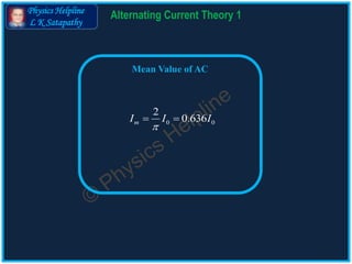
- 1. Physics Helpline L K Satapathy Alternating Current Theory 1 Mean Value of AC 0 0 2 0.636mI I I
- 2. Physics Helpline L K Satapathy Cells in Parallel Alternating Current Theory 1 Alternating Current : Electric current whose magnitude changes continuously and direction (polarity) reverses periodically with time is known as Alternating Current. Alternating current which varies sinusoidally with time is given by 0 0 2 sin sinI I t I t T Peak value (Amplitude)0I Angular frequency Time periodT I t 2 T0 T
- 3. Physics Helpline L K Satapathy Cells in Parallel Alternating Current Theory 1 Mean value of AC : It is that value of steady current which will send the same amount of charge through a resistor in a half cycle of AC as is sent by the alternating current through the same resistor in the same time. I t 2 TO 1 2 3 n 2 T t n 1 2, , . . . , ni i i 1 1 2 2, , . . . , n nq i t q i t q i t 1 2 1 2... ( . . . )n nq q q q i i i t Half cycle (T/2) of an AC is shown in the figure Divide it into n equal time intervals (t) Let the currents in these intervals be Charge sent in these intervals are Total charge sent in the half cycle is given by 1 2( . . . ) . . . (1) 2 n T q i i i n
- 4. Physics Helpline L K Satapathy Cells in Parallel Alternating Current Theory 1 I t 2 TO mI 1 2(1) & (2) ( . . . ) 2 2 m n I T T i i i n 1 2 . . . n m i i i I n Let the mean value of AC = Im Charge sent by it in time (T/2) is given by . . . (2) 2 mI T q
- 5. Physics Helpline L K Satapathy Cells in Parallel Alternating Current Theory 1 0 sin dq I I t dt Charge sent by AC in time T/2 is 2 0 0 cos T t I 0 [cos( 2) cos0] I T 0 sin .dq I t dt Relation between Mean value and Peak value of AC : Instantaneous current 2 0 0 sin . T q I t dt
- 6. Physics Helpline L K Satapathy Cells in Parallel Alternating Current Theory 1 0 2 mI T I T (2) 2 mI T Also q 2 2T T 0 [cos cos0] 2 I q T 0 [ 1 1] 2 I T 0 0 ( 2) 2 I T I T 0 0 0 2 7 0.636 11 mI I I I
- 7. Physics Helpline L K Satapathy For More details: www.physics-helpline.com Subscribe our channel: youtube.com/physics-helpline Follow us on Facebook and Twitter: facebook.com/physics-helpline twitter.com/physics-helpline