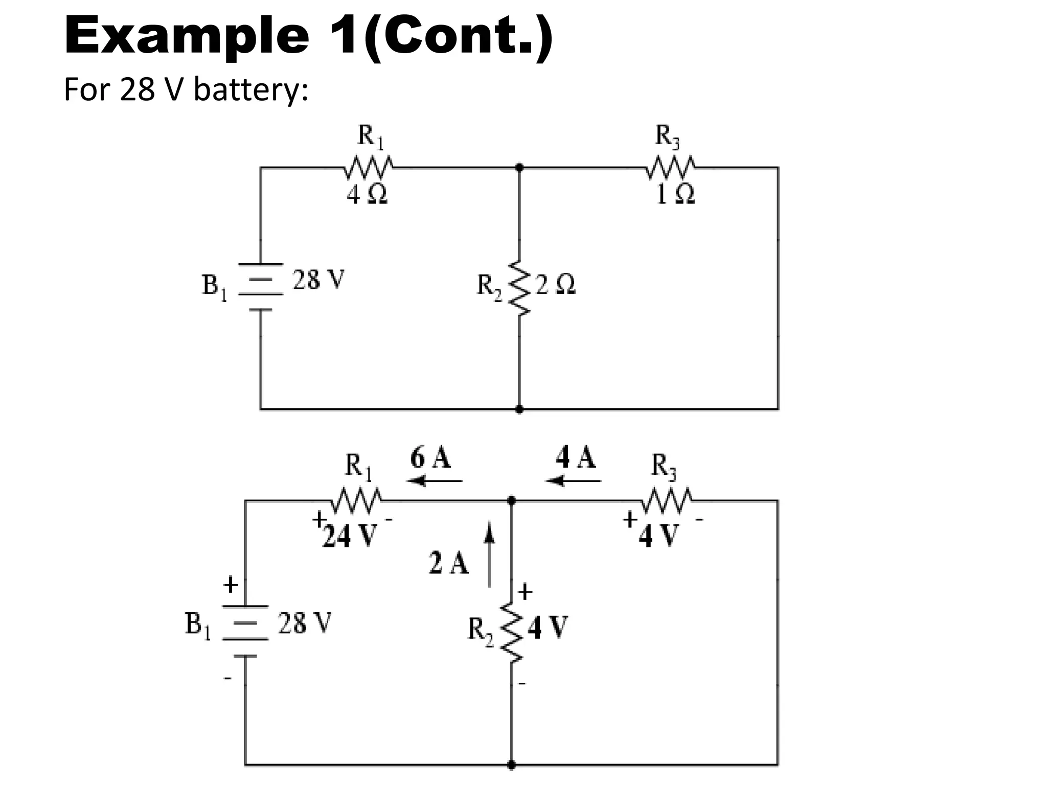
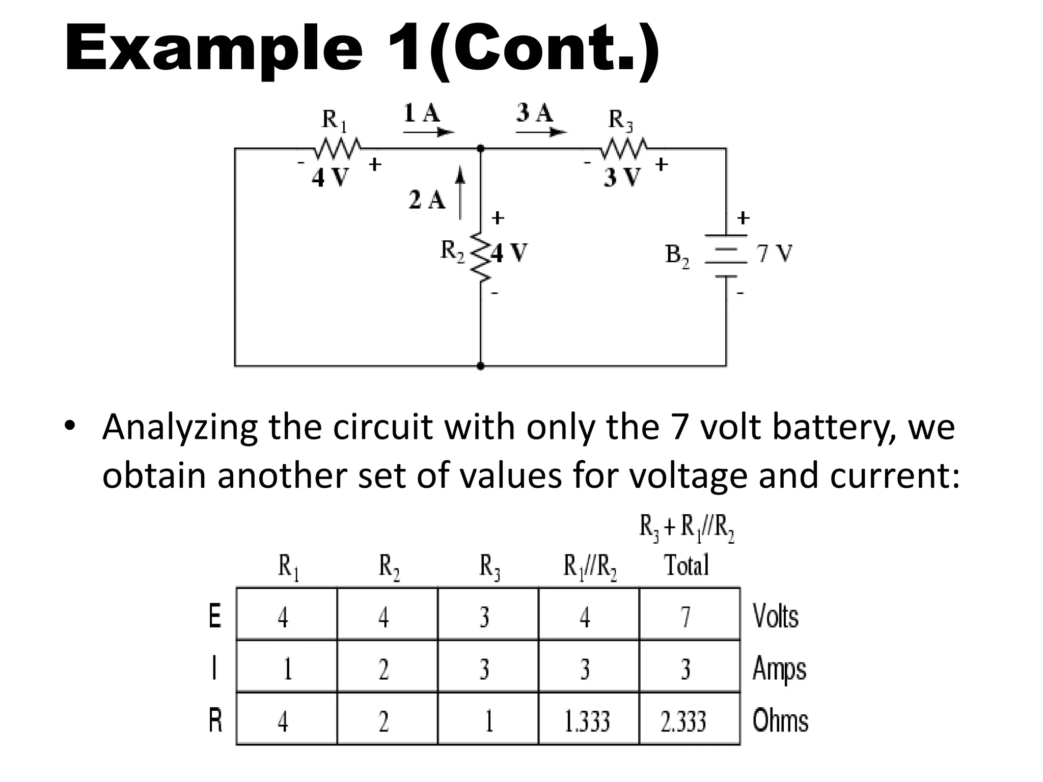
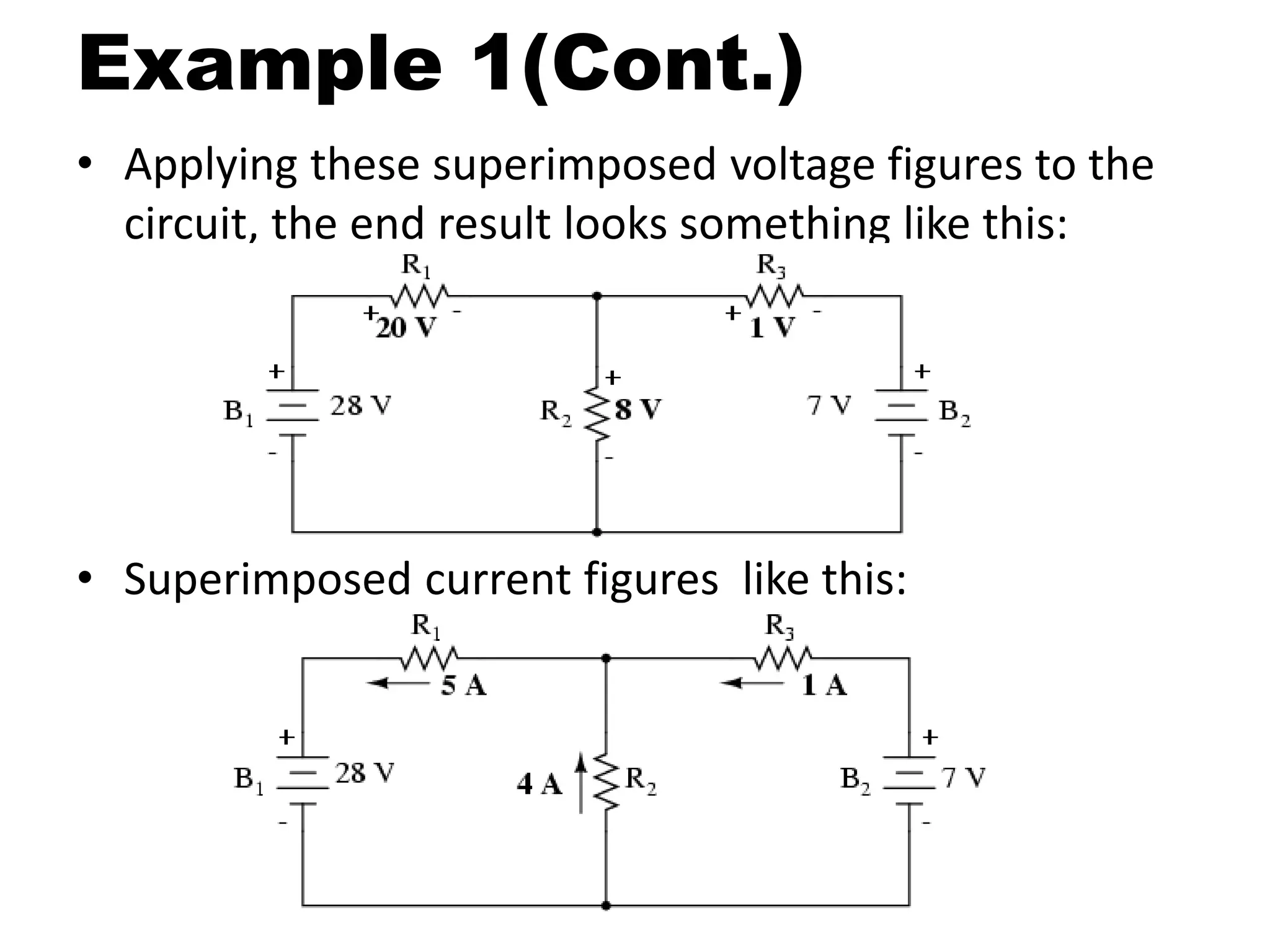
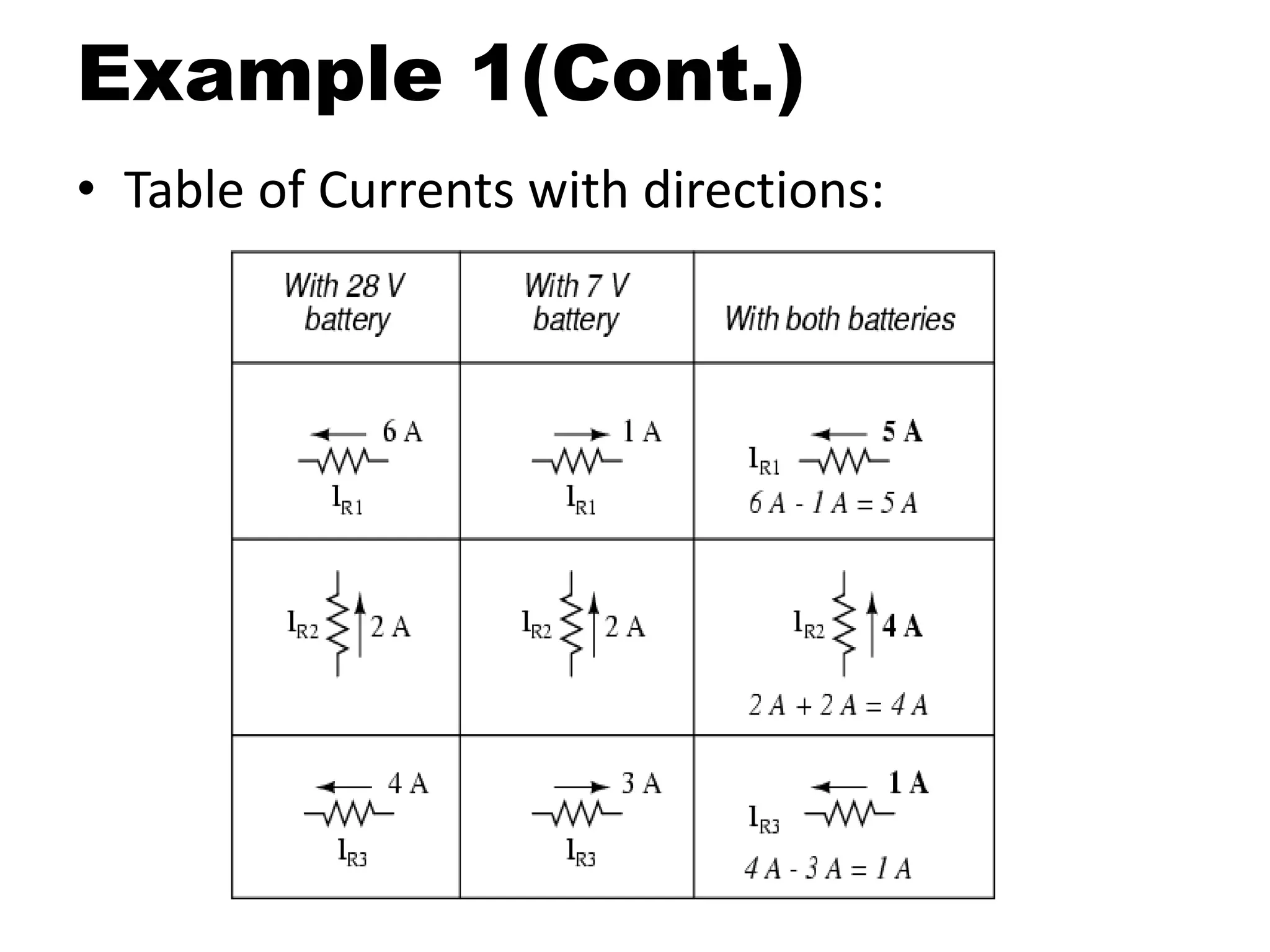
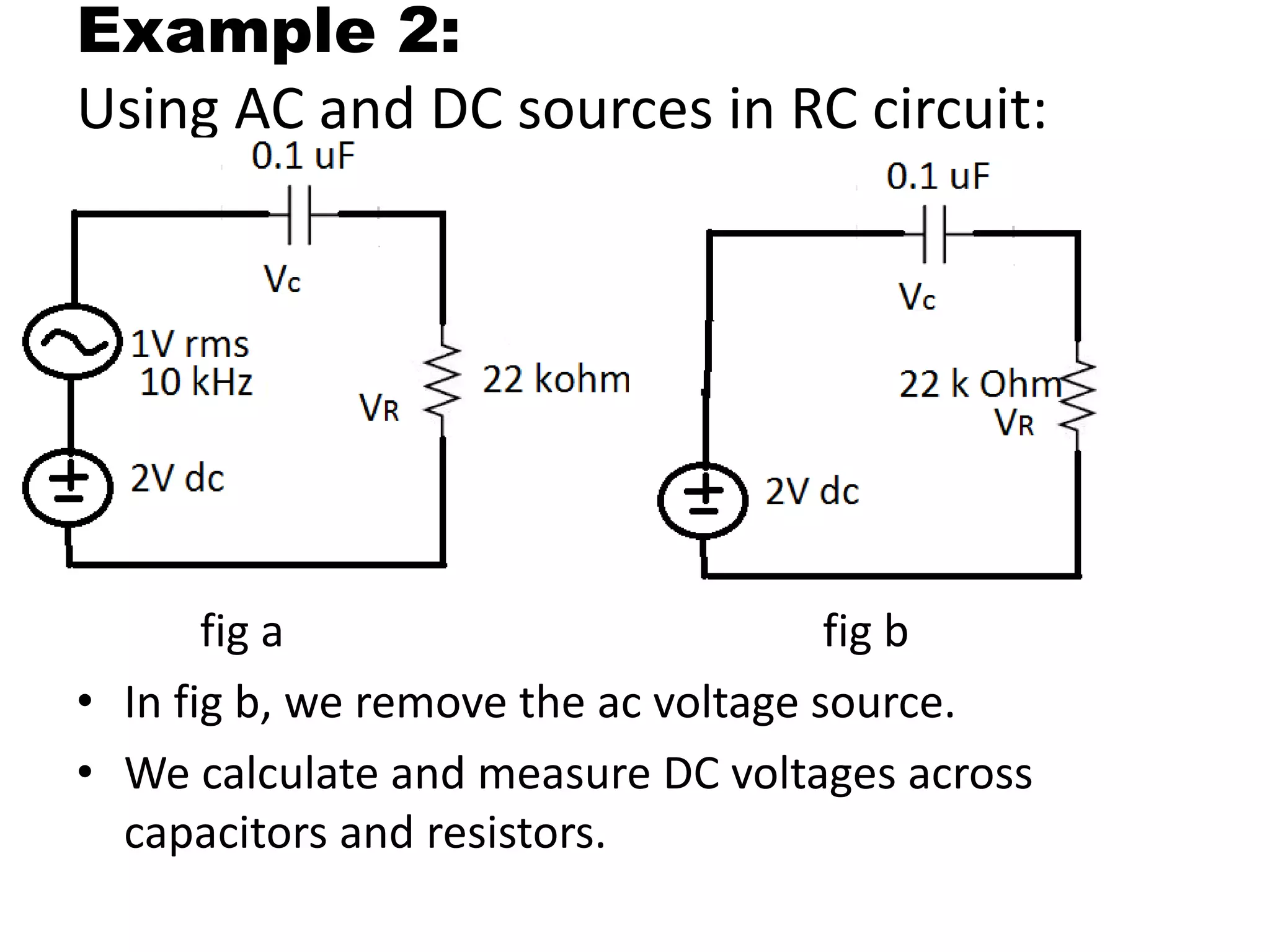
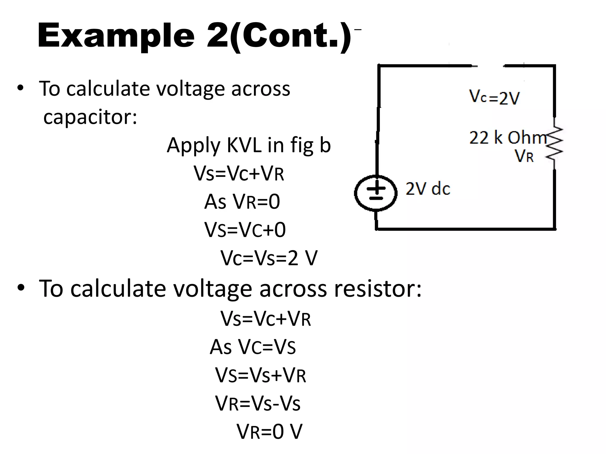
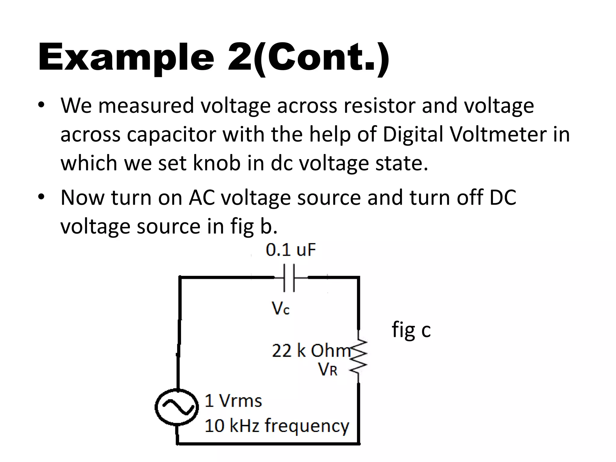
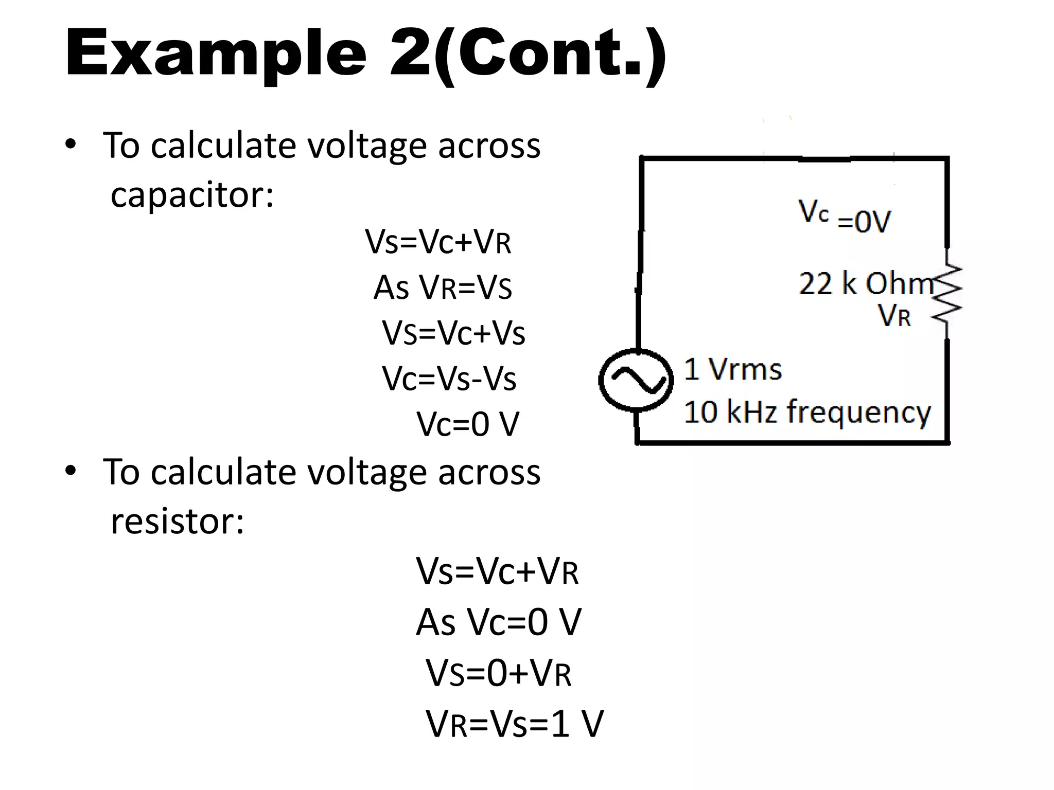
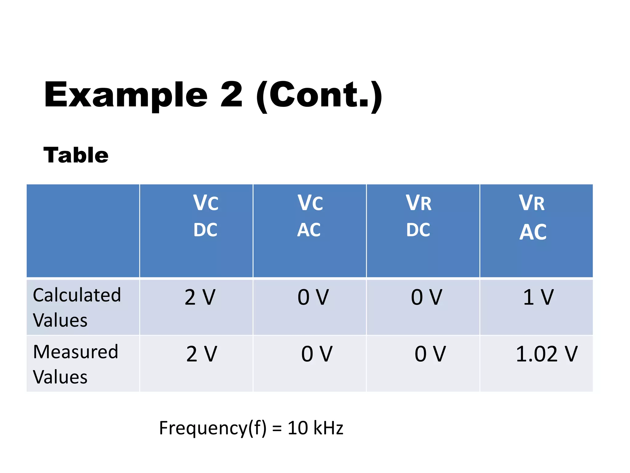
This document discusses superposition and its use in analyzing circuits with both AC and DC sources. Superposition allows a circuit to be solved by separately analyzing the individual effects of each independent source. The key steps are to solve the circuit for each source alone by shorting or opening the other sources; then combine the individual voltage and current results. Example 1 uses two DC sources in a circuit to demonstrate the technique. Example 2 applies superposition to an RC circuit with both an AC and DC source, calculating and measuring the separate and combined voltage effects across the resistor and capacitor.
this slides are used for the definition of capacitor and inductor and also it types
this slides describe circuit of capacitor and inductors like capacitor in series and parallel and vice versa
Bipolar Junction Transistor (BJT) DC and AC AnalysisJess Rangcasajo
BJT AC and DC Analysis
This slide condenses the two ways analysis of BJT (AC and DC).
At the end of the slide, it has review question answer with answer key as providing.
Zero crossing detector detects how many times the input signal crossed the Zero value or Zero voltage level. Zero cross detector is basically a comparator circuit that compares the input sinusoidal signal or Sine wave signal with the zero voltage level, In other words, we can say that this detects the voltage changing from positive level to negative level and negative level to positive level. The output of the zero-cross detector changes when the input voltage crosses the zero level to High or High to zero.
The performance obtainable from a single-stage amplifier is often insufficient for many applications, hence several stages may be combined forming a multistage amplifier. These stages are connected in cascade, i.e. output of the first stage is connected to form input of second stage, whose output becomes input of third stage, and so on.
thank u
Hansraj MEENA
Superposition Principle in Electric Circuit Fundamentals and Electrical Engin...Electrical Slides
Superposition principle is an important theorem in Electric Circuit fundamentals, It involves the calculation of current and voltage contributions separately from all sources in any circuit and then to sum up all these values for calculating overall voltage and current effects on any resistor or component. Superposition theorem is an important theorem which relieves problem of solving complex simultaneous problems. While, apply principle to any circuit, current sources are made open, whereas voltage sources are suppressed to short circuit.
An electric circuit is a path in which electrons from a voltage or current source flow. The point where those electrons enter an electrical circuit is called the "source" of electrons.
To understand the basic working principle of a transformer.
To obtain the equivalent circuit parameters from Open circuit and Short circuit tests, and to estimate efficiency & regulation at various loads.
Sesión de Laboratorio 3: Leyes de Kirchhoff, Circuitos RC y DiodosJavier García Molleja
Laboratory session in Physics II subject for September 2016-January 2017 semester in Yachay Tech University (Ecuador). Topic covered: electricity, electrical circuits, resistances, capacitances, diodes
Based on Bruna Regalado's work
Ekeeda Provides Online Video Lectures, Tutorials & Engineering Courses Available for Top-Tier Universities in India. Lectures from Highly Trained & Experienced Faculty!
Ekeeda - First Year Enginering - Basic Electrical EngineeringEkeedaPvtLtd
The First Year engineering course seems more like an extension of the subjects that students have learned in their 12th class. Subjects like Engineering Physics, Chemistry, and Mathematics, are incorporated into the curriculum. Students will learn about some of the engineering subjects in this first year, and these subjects are similar to all the branches. Everyone will learn some basics related to the other streams in their first year. Ekeeda offers Online First Year Engineering Courses for all the Subjects as per the Syllabus.
Sachpazis:Terzaghi Bearing Capacity Estimation in simple terms with Calculati...Dr.Costas Sachpazis
Terzaghi's soil bearing capacity theory, developed by Karl Terzaghi, is a fundamental principle in geotechnical engineering used to determine the bearing capacity of shallow foundations. This theory provides a method to calculate the ultimate bearing capacity of soil, which is the maximum load per unit area that the soil can support without undergoing shear failure. The Calculation HTML Code included.
Forklift Classes Overview by Intella PartsIntella Parts
Discover the different forklift classes and their specific applications. Learn how to choose the right forklift for your needs to ensure safety, efficiency, and compliance in your operations.
For more technical information, visit our website https://intellaparts.com
We have compiled the most important slides from each speaker's presentation. This year’s compilation, available for free, captures the key insights and contributions shared during the DfMAy 2024 conference.
Saudi Arabia stands as a titan in the global energy landscape, renowned for its abundant oil and gas resources. It's the largest exporter of petroleum and holds some of the world's most significant reserves. Let's delve into the top 10 oil and gas projects shaping Saudi Arabia's energy future in 2024.
Cosmetic shop management system project report.pdfKamal Acharya
Buying new cosmetic products is difficult. It can even be scary for those who have sensitive skin and are prone to skin trouble. The information needed to alleviate this problem is on the back of each product, but it's thought to interpret those ingredient lists unless you have a background in chemistry.
Instead of buying and hoping for the best, we can use data science to help us predict which products may be good fits for us. It includes various function programs to do the above mentioned tasks.
Data file handling has been effectively used in the program.
The automated cosmetic shop management system should deal with the automation of general workflow and administration process of the shop. The main processes of the system focus on customer's request where the system is able to search the most appropriate products and deliver it to the customers. It should help the employees to quickly identify the list of cosmetic product that have reached the minimum quantity and also keep a track of expired date for each cosmetic product. It should help the employees to find the rack number in which the product is placed.It is also Faster and more efficient way.
About
Indigenized remote control interface card suitable for MAFI system CCR equipment. Compatible for IDM8000 CCR. Backplane mounted serial and TCP/Ethernet communication module for CCR remote access. IDM 8000 CCR remote control on serial and TCP protocol.
• Remote control: Parallel or serial interface.
• Compatible with MAFI CCR system.
• Compatible with IDM8000 CCR.
• Compatible with Backplane mount serial communication.
• Compatible with commercial and Defence aviation CCR system.
• Remote control system for accessing CCR and allied system over serial or TCP.
• Indigenized local Support/presence in India.
• Easy in configuration using DIP switches.
Technical Specifications
Indigenized remote control interface card suitable for MAFI system CCR equipment. Compatible for IDM8000 CCR. Backplane mounted serial and TCP/Ethernet communication module for CCR remote access. IDM 8000 CCR remote control on serial and TCP protocol.
Key Features
Indigenized remote control interface card suitable for MAFI system CCR equipment. Compatible for IDM8000 CCR. Backplane mounted serial and TCP/Ethernet communication module for CCR remote access. IDM 8000 CCR remote control on serial and TCP protocol.
• Remote control: Parallel or serial interface
• Compatible with MAFI CCR system
• Copatiable with IDM8000 CCR
• Compatible with Backplane mount serial communication.
• Compatible with commercial and Defence aviation CCR system.
• Remote control system for accessing CCR and allied system over serial or TCP.
• Indigenized local Support/presence in India.
Application
• Remote control: Parallel or serial interface.
• Compatible with MAFI CCR system.
• Compatible with IDM8000 CCR.
• Compatible with Backplane mount serial communication.
• Compatible with commercial and Defence aviation CCR system.
• Remote control system for accessing CCR and allied system over serial or TCP.
• Indigenized local Support/presence in India.
• Easy in configuration using DIP switches.
NUMERICAL SIMULATIONS OF HEAT AND MASS TRANSFER IN CONDENSING HEAT EXCHANGERS...ssuser7dcef0
Power plants release a large amount of water vapor into the
atmosphere through the stack. The flue gas can be a potential
source for obtaining much needed cooling water for a power
plant. If a power plant could recover and reuse a portion of this
moisture, it could reduce its total cooling water intake
requirement. One of the most practical way to recover water
from flue gas is to use a condensing heat exchanger. The power
plant could also recover latent heat due to condensation as well
as sensible heat due to lowering the flue gas exit temperature.
Additionally, harmful acids released from the stack can be
reduced in a condensing heat exchanger by acid condensation. reduced in a condensing heat exchanger by acid condensation.
Condensation of vapors in flue gas is a complicated
phenomenon since heat and mass transfer of water vapor and
various acids simultaneously occur in the presence of noncondensable
gases such as nitrogen and oxygen. Design of a
condenser depends on the knowledge and understanding of the
heat and mass transfer processes. A computer program for
numerical simulations of water (H2O) and sulfuric acid (H2SO4)
condensation in a flue gas condensing heat exchanger was
developed using MATLAB. Governing equations based on
mass and energy balances for the system were derived to
predict variables such as flue gas exit temperature, cooling
water outlet temperature, mole fraction and condensation rates
of water and sulfuric acid vapors. The equations were solved
using an iterative solution technique with calculations of heat
and mass transfer coefficients and physical properties.
2. Contents of Presentation
• What is Superposition?
• Usage of Superposition.
• Steps of Superposition with dc independent
sources.
• Example 1 - Using two independent DC
sources.
• Steps of superposition with ac and dc sources.
• Example 2 - Using AC and DC sources in RC
circuit.
3. What is Superposition?
• The voltage across a component is the
algebraic sum of the voltage across the
component due to each independent source
acting upon it.
• The current flowing through a component is
the algebraic sum of the current flowing
through component due to each independent
source acting upon it.
4. Usage of Superposition
• Separating the contributions of the DC and AC
independent sources.
Example:
To determine the performance of an amplifier, we
calculate the DC voltages and currents to establish
the bias point.
The AC signal is usually what will be amplified.
A generic amplifier has a constant DC operating
point, but the AC signal’s amplitude and frequency
will vary depending on the application.
5. Usage of Superposition (Cont.)
Superposition can be used to reduce the
complexity of a circuit so that the voltages and
currents in the circuit can be determined easily.
To turn off a voltage source, replace it with a short
circuit.
To turn off a current source, replace it with an open
circuit.
Polarity of voltage across components and direction of
currents through the components must be the same
during each iteration through the circuit.
The total of the currents and voltages from each
iteration is the solution when all sources are active in
the circuit
6. Steps of Superposition with
DC Independent Sources
• Turn off all independent sources except one.
• Redraw circuit.
• Solve for the voltages and currents in the new
circuit.
• Turn off the active independent source and turn
on one of the other independent sources.
• Repeat Steps 2 and 3.
• Continue until you have turned on each of the
independent sources in the original circuit.
• To find the total voltage across each component
and the total current flowing, add the
contributions from each of the voltages and
currents found in Step 3.
7. Example 1
Using two independent DC sources:
• Since we have two sources of power in this circuit,
we will have to calculate two sets of values for
voltage drops and/or currents, one for the circuit
with only the 28 volt battery in effect and one for the
circuit with only the 7 volt battery in effect.
9. Example 1 (Cont.)
• Analyzing the circuit with only the 28 volt battery, we
obtain the following values for voltage and current:
• For 7 V battery:
10. Example 1(Cont.)
• Analyzing the circuit with only the 7 volt battery, we
obtain another set of values for voltage and current:
11. Example 1(Cont.)
• Applying these superimposed voltage figures to the
circuit, the end result looks something like this:
• Superimposed current figures like this:
14. Steps of Superposition with
AC and DC Sources
• Turn off AC voltage source except DC voltage source.
• Redraw the circuit.
• In RC circuit, capacitor act as an open for DC voltage
source whereas in RL circuit inductor act as closed
for DC voltage source.
• Calculate and measured DC voltages across
capitor(or inductor) and resistor.
• For DC source, if we use RC circuit then voltage
across capacitor is equal to DC supply voltage, and
voltage across resistor is zero. Else if we use RL circuit
then voltage across inductor is zero, and voltage
across resistor is equal to dc supply voltage.
15. Steps of Superposition with
AC and DC sources (Cont.)
• Now turn on AC voltage source and turn off DC voltage
source.
• Repeat step 2.
• In RC circuit, capacitor act as short for AC voltage source
whereas in RL circuit, inductor act as open for AC voltage
source.
• Calculate and measured AC voltages across capacitor(or
inductor) and resistor.
• For ac source, if we use RC circuit then voltage across
resistor is equal to AC supply voltage, and voltage across
capacitor is zero. Else if we use RL circuit then voltage
across resistor is zero, and voltage across inductor is
equal to AC supply voltage.
• Superimposed both the sources and check AC and DC
voltages across capacitor(or inductor) and resistor with
the help of oscilloscope in AC coupling and DC coupling.
16. Example 2:
Using AC and DC sources in RC circuit:
fig a fig b
• In fig b, we remove the ac voltage source.
• We calculate and measure DC voltages across
capacitors and resistors.
17. Example 2(Cont.):
• To calculate voltage across
capacitor:
Apply KVL in fig b
Vs=Vc+VR
As VR=0
VS=VC+0
Vc=Vs=2 V
• To calculate voltage across resistor:
Vs=Vc+VR
As VC=VS
VS=Vs+VR
VR=Vs-Vs
VR=0 V
18. Example 2(Cont.)
• We measured voltage across resistor and voltage
across capacitor with the help of Digital Voltmeter in
which we set knob in dc voltage state.
• Now turn on AC voltage source and turn off DC
voltage source in fig b.
fig c
19. Example 2(Cont.)
• To calculate voltage across
capacitor:
Vs=Vc+VR
As VR=VS
VS=Vc+Vs
Vc=Vs-Vs
Vc=0 V
• To calculate voltage across
resistor:
Vs=Vc+VR
As Vc=0 V
VS=0+VR
VR=Vs=1 V