Downloaded 156 times
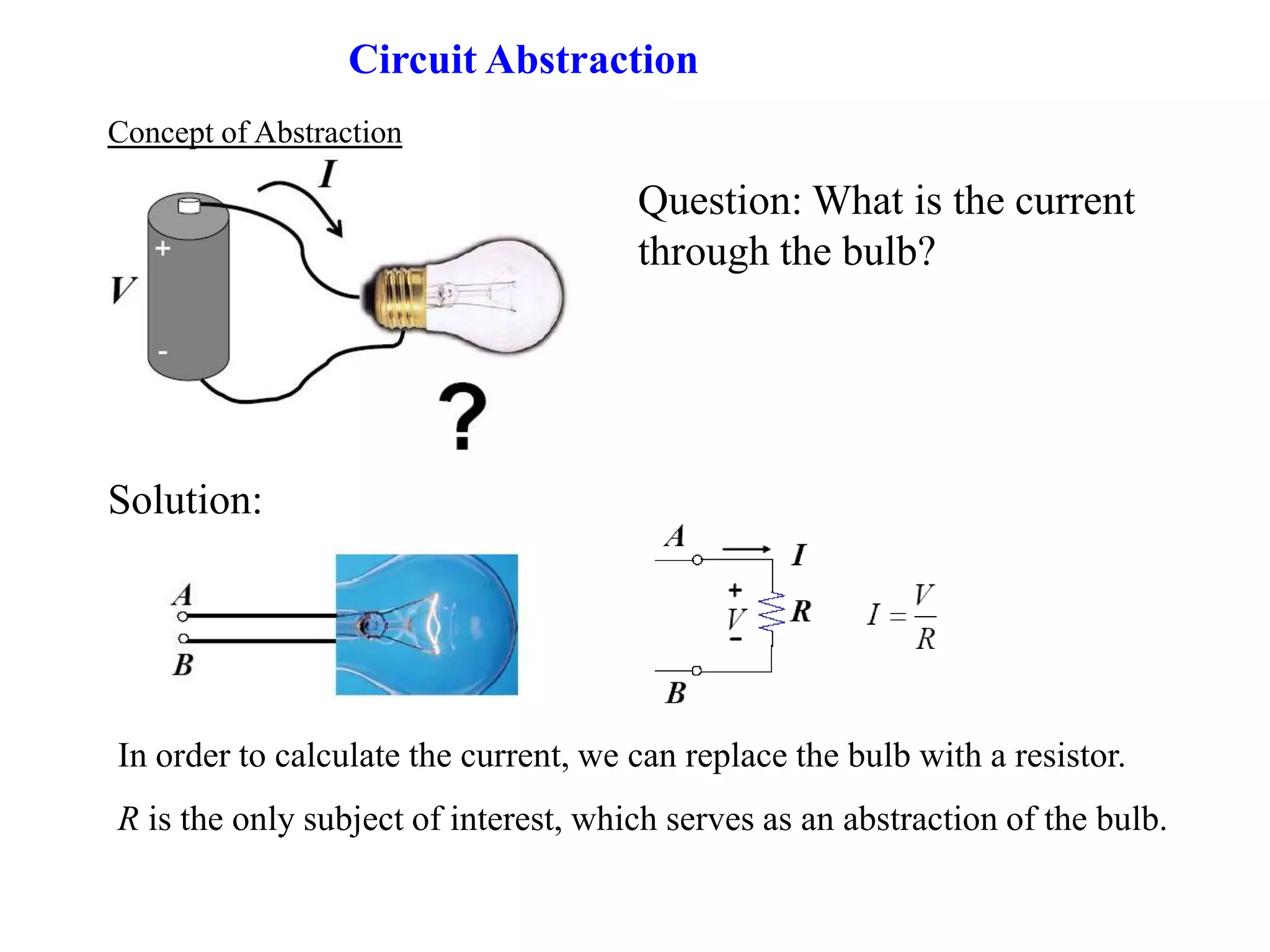
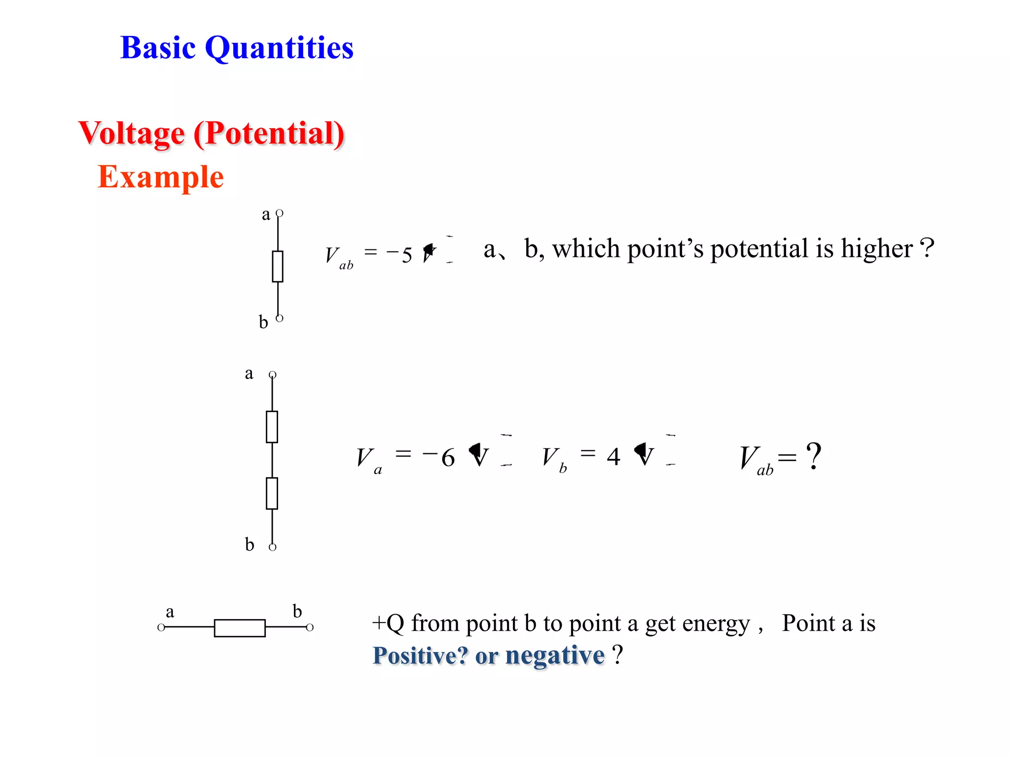
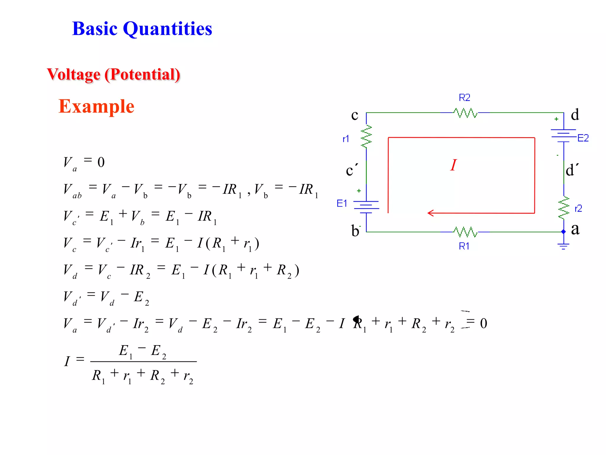
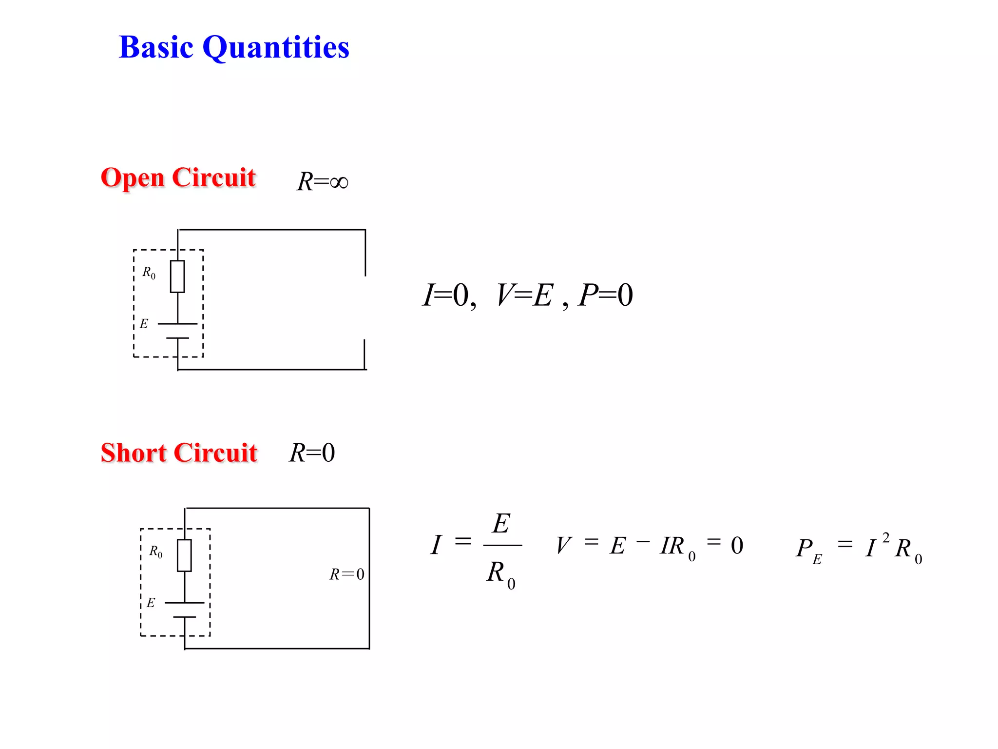
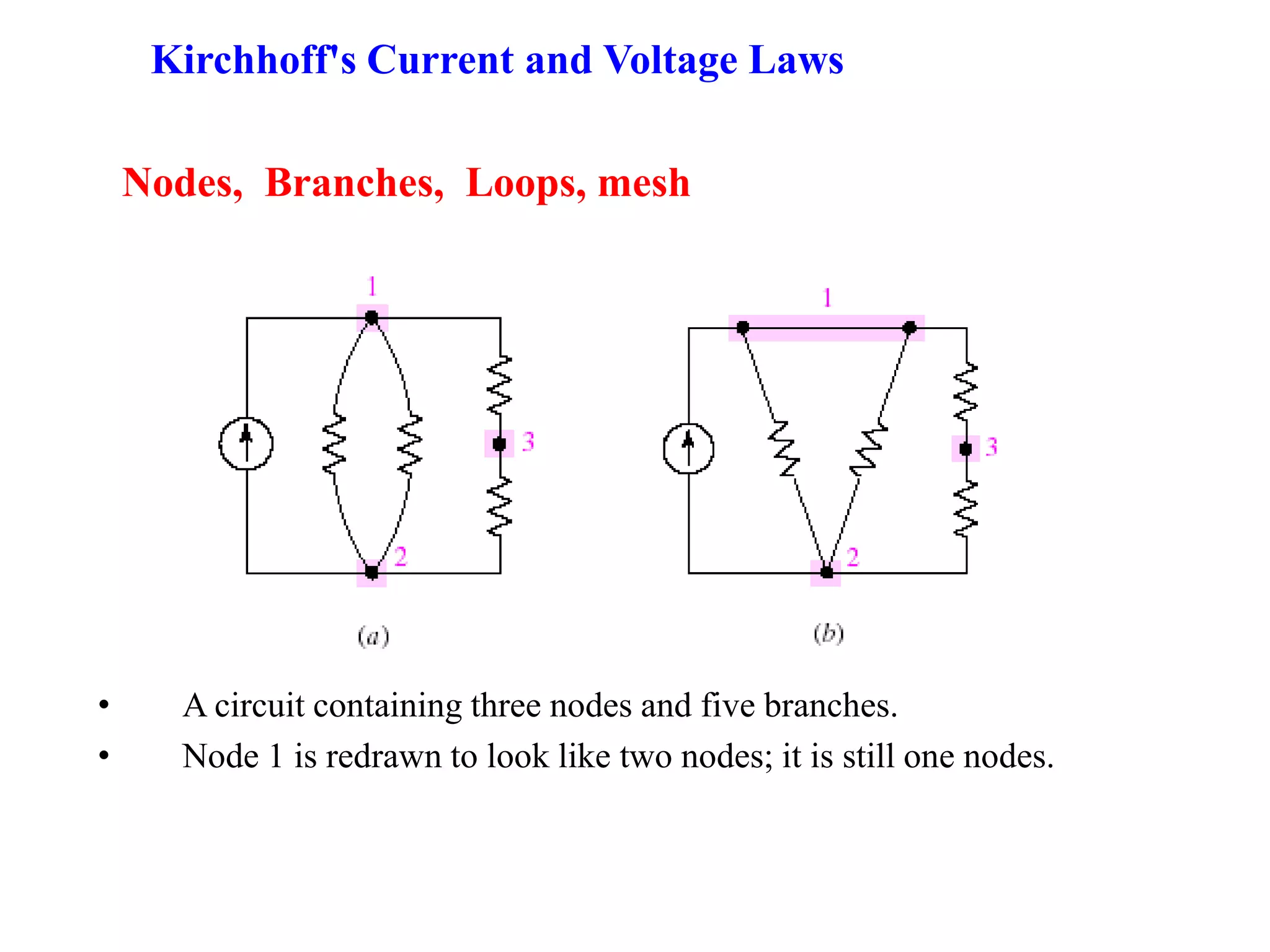

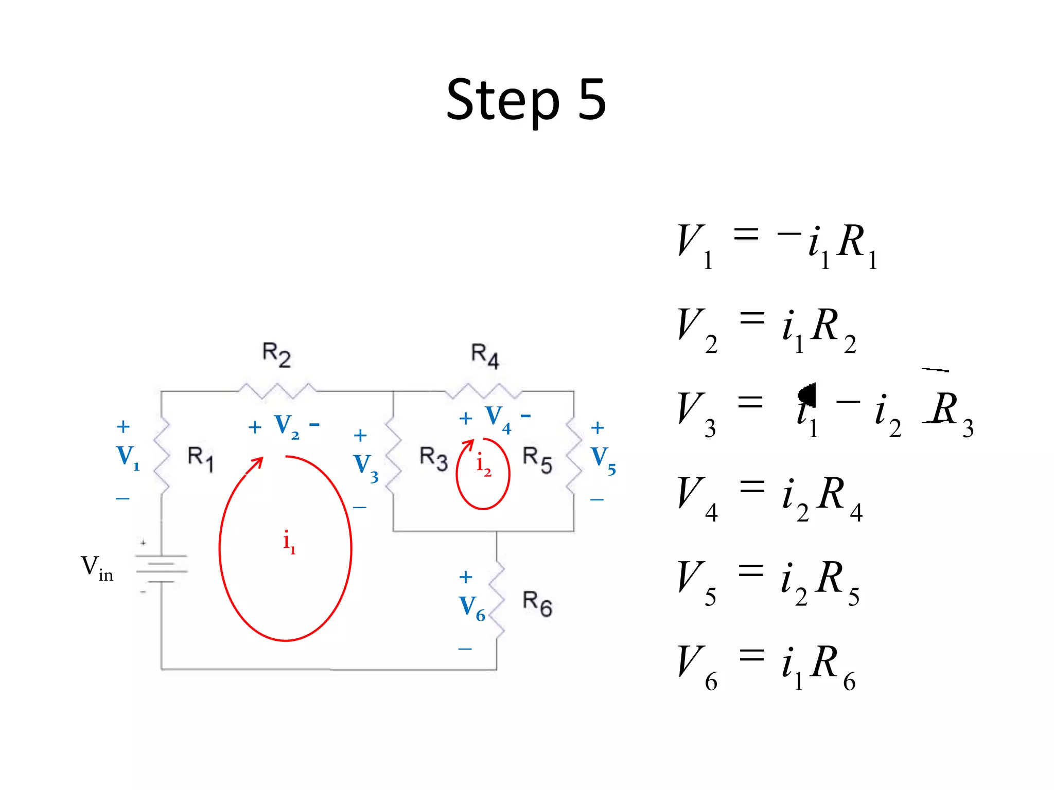
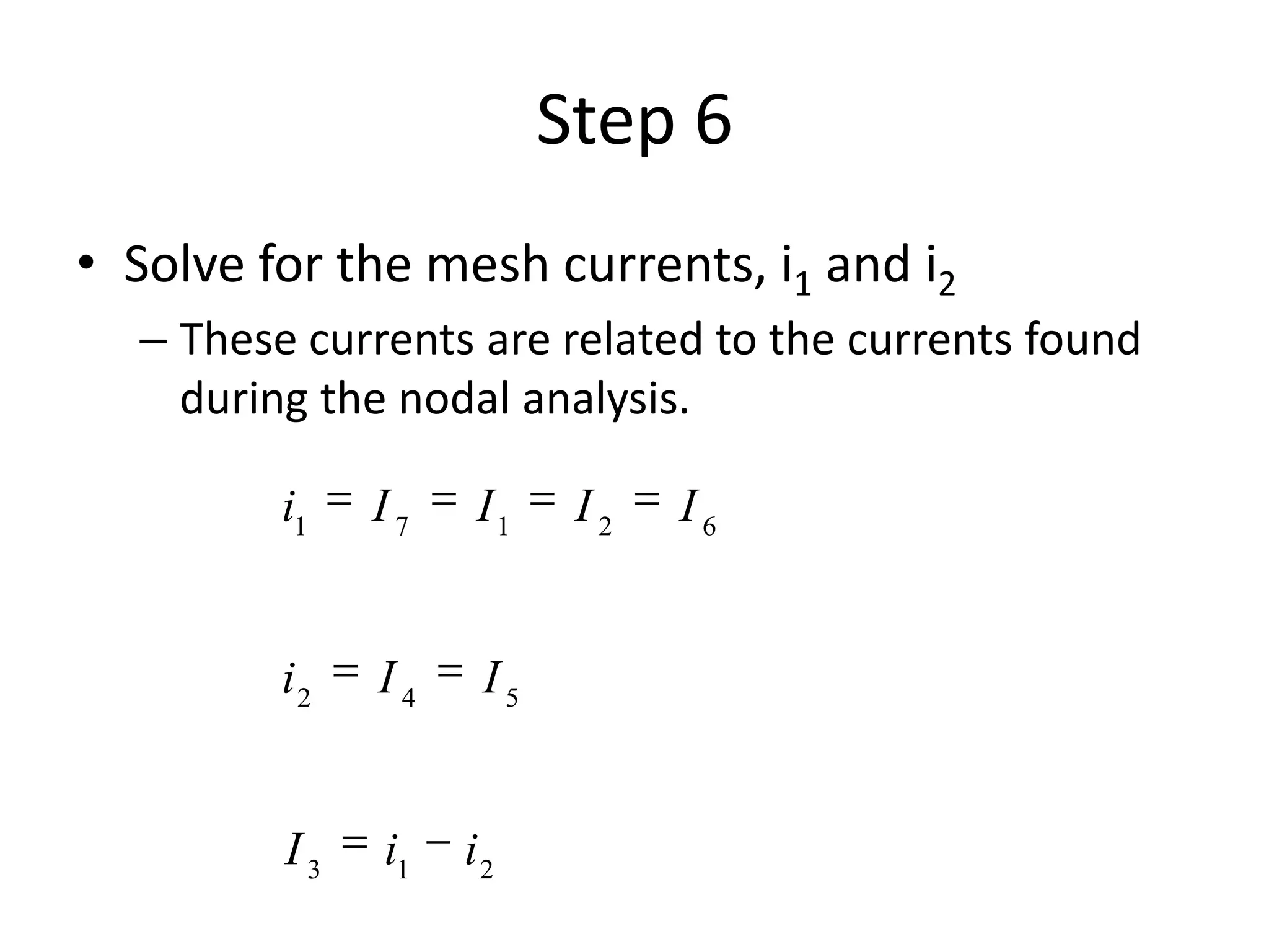
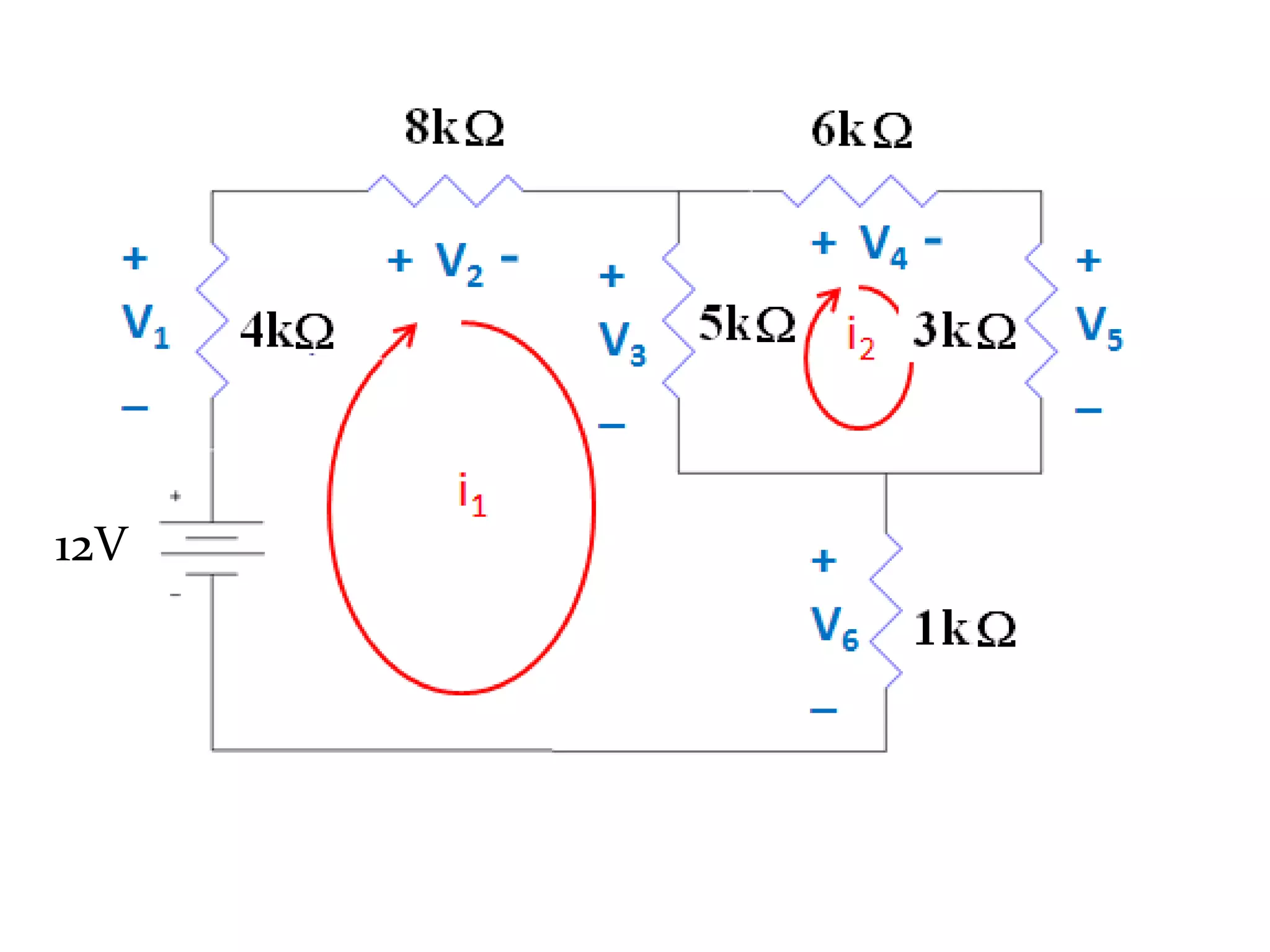

1) The document discusses basic circuit analysis techniques including circuit abstraction, voltage, current, resistance, nodes, branches, loops, and Kirchhoff's laws. 2) Key circuit concepts covered are open and short circuits, voltage and current division, and mesh analysis. 3) Mesh analysis involves identifying all loops in a circuit, labeling loop currents, applying Kirchhoff's laws, and solving equations to determine the currents through each component.


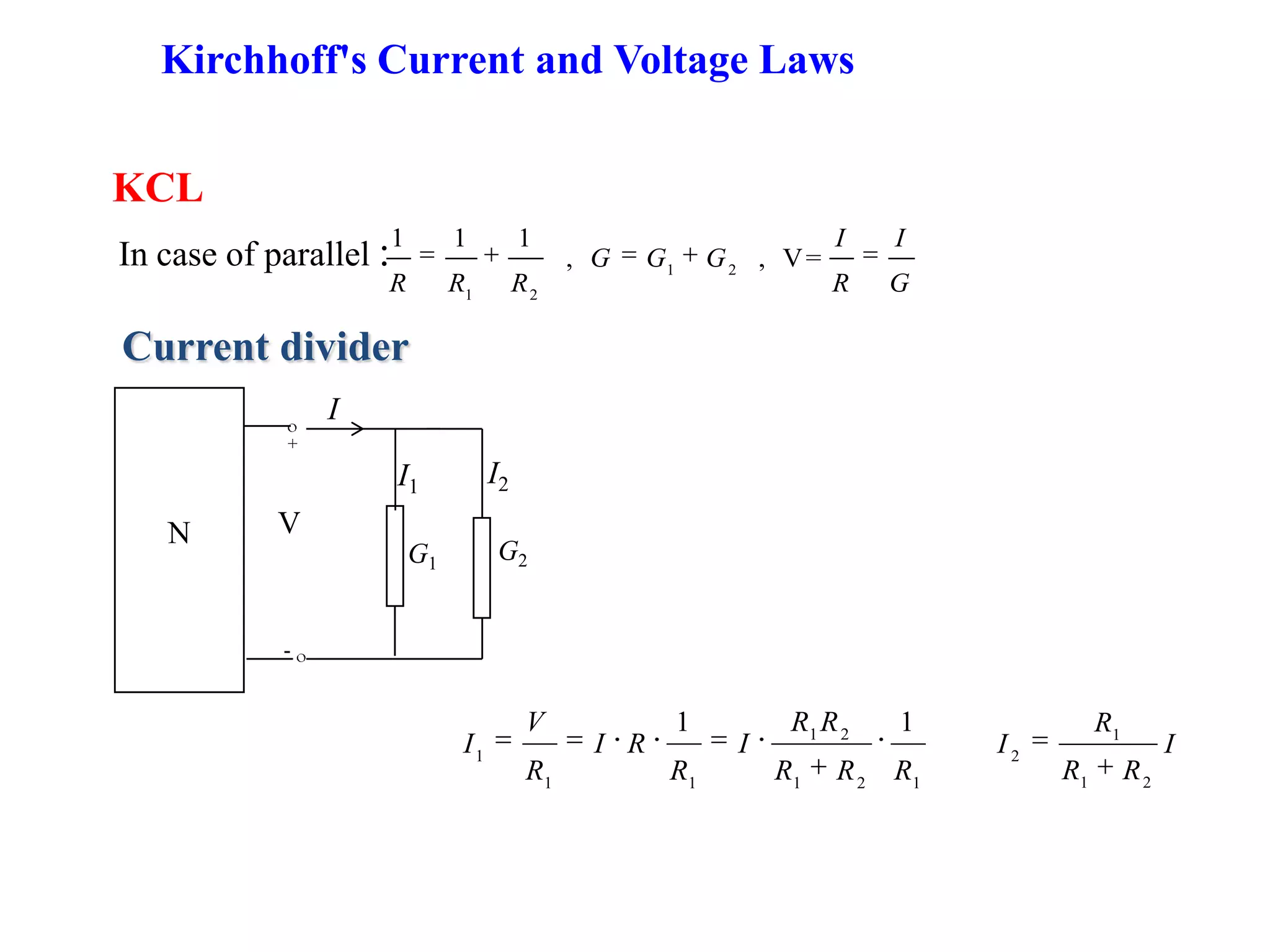
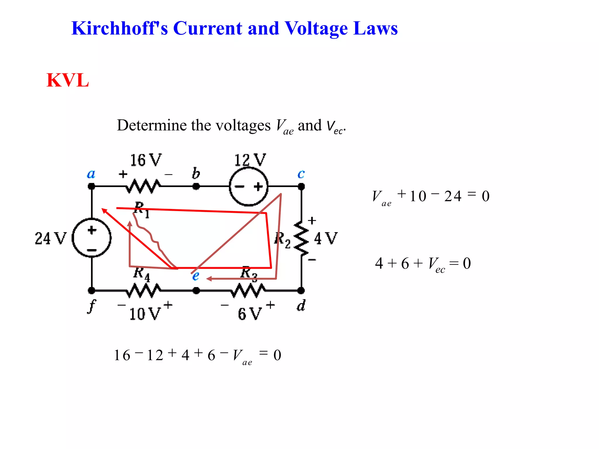
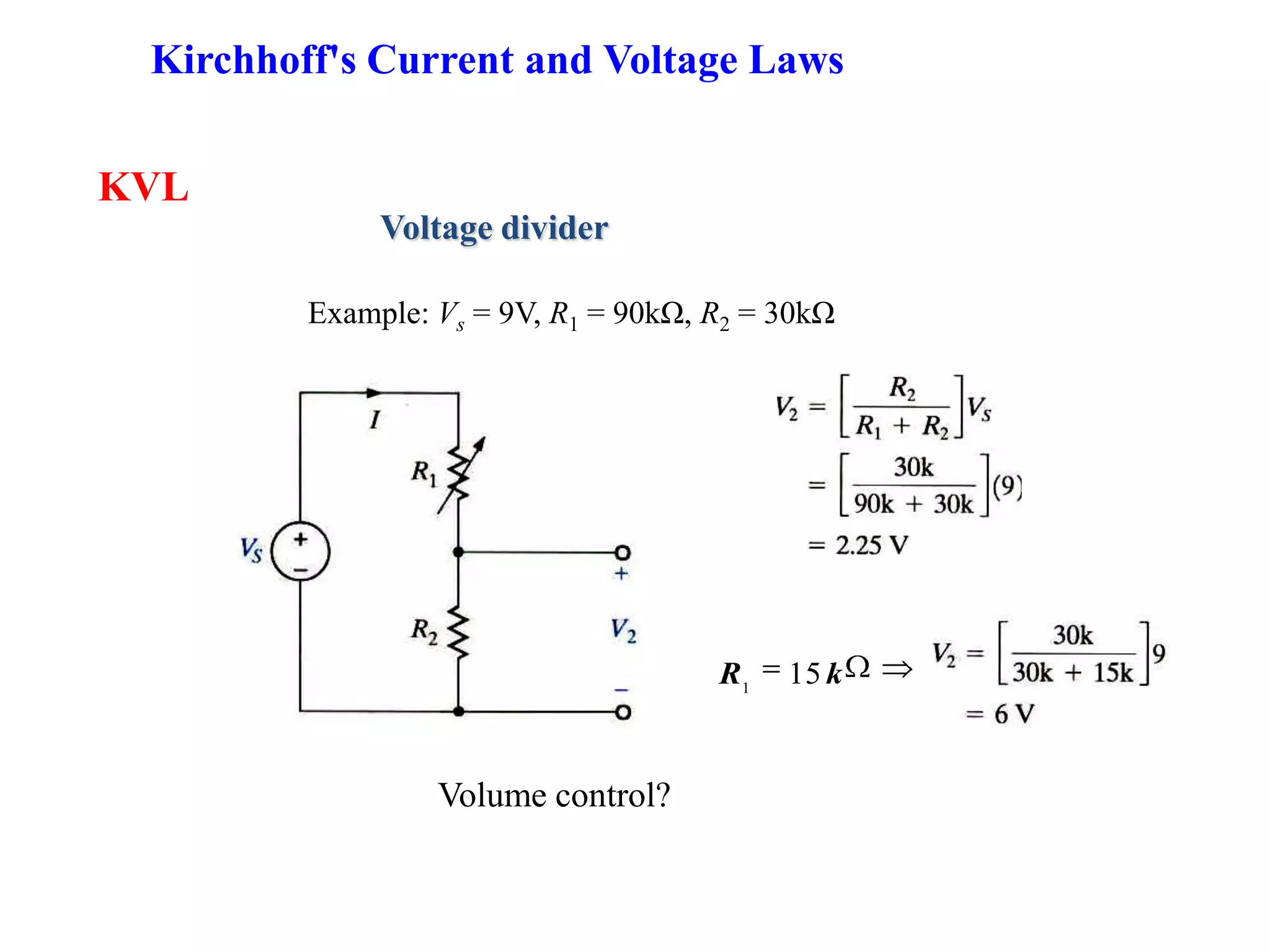
![[Slideshare] tafaqqahu-(2015)-#6 e-responding-islamaphobia-regardg-islamic-la...](https://cdn.slidesharecdn.com/ss_thumbnails/slideshare-tafaqqahu-2015-6e-responding-islamaphobia-regardg-islamic-law-16-may-2015-150516155252-lva1-app6891-thumbnail.jpg?width=640&height=640&fit=bounds)