SlideShare a Scribd company logo
ATOMIC ENERGY CENTRAL SCHOOL, MYSORE
DISTANT LEARNING PROGRAM 2020-21
CHAPTER-7
ALTERNATING CURRENT
PPT- (1 of 2 )
PREPARED BY: P.SARAVANAN
INTRODUCTION:
An alternating voltage is the voltage which changes polarity at regular intervals of time and the direction of the resulting
alternating current also changes accordingly.
If the wave form of alternating voltage is a sine wave, then it is known as “ sinusoidal alternating voltage ”. It is given by
v = 𝒗𝒎 sin ωt
where, v → instantaneous value of alternating voltage
𝑣𝑚 → voltage amplitude (or) maximum value of alternating voltage
ω → angular frequency of alternating voltage
When sinusoidal alternating voltage is applied to a closed circuit, the resulting current also is sinusoidal in nature.
It is given by the relation
i = 𝒊𝒎 sin ωt
where, i → instantaneous value of alternating current
𝑖𝑚 → current amplitude (or) maximum value of alternating current
ω → angular frequency of alternating current
The direction of sinusoidal voltage or current is reversed after every half-cycle and its magnitude is
also changing continuously as shown in figure below.
Alternating voltage Alternating current
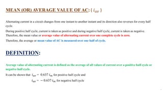
MEAN (OR) AVERAGE VALUE OF AC: ( 𝑖𝑎𝑣 )
Alternating current in a circuit changes from one instant to another instant and its direction also reverses for every half
cycle.
During positive half cycle, current is taken as positive and during negative half cycle, current is taken as negative.
Therefore, the mean value or average value of alternating current over one complete cycle is zero.
Therefore, the average or mean value of AC is measured over one half of cycle.
DEFINITION:
Average value of alternating current is defined as the average of all values of current over a positive half cycle or
negative half cycle.
It can be shown that 𝑖𝑎𝑣 = 0.637 𝑖𝑚 for positive half cycle and
𝑖𝑎𝑣 = − 0.637 𝑖𝑚 for negative half cycle
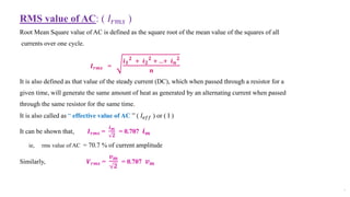
RMS value of AC: ( 𝐼𝑟𝑚𝑠 )
Root Mean Square value of AC is defined as the square root of the mean value of the squares of all
currents over one cycle.
𝑰𝒓𝒎𝒔 =
𝒊𝟏
𝟐
+ 𝒊𝟐
𝟐
+ ...+ 𝒊𝒏
𝟐
𝒏
It is also defined as that value of the steady current (DC), which when passed through a resistor for a
given time, will generate the same amount of heat as generated by an alternating current when passed
through the same resistor for the same time.
It is also called as “ effective value of AC ” ( 𝐼𝑒𝑓𝑓 ) or ( I )
It can be shown that, 𝑰𝒓𝒎𝒔 =
𝒊𝒎
𝟐
= 0.707 𝒊𝒎
ie, rms value of AC = 70.7 % of current amplitude
Similarly, 𝑽𝒓𝒎𝒔 =
𝒗𝒎
𝟐
= 0.707 𝒗𝒎
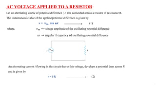
AC VOLTAGE APPLIED TO A RESISTOR:
Let an alternating source of potential difference ( 𝜀 ) be connected across a resistor of resistance R.
The instantaneous value of the applied potential difference is given by
v = 𝒗𝒎 sin ωt (1)
where, 𝑣𝑚 → voltage amplitude of the oscillating potential difference
ω → angular frequency of oscillating potential difference
An alternating current i flowing in the circuit due to this voltage, develops a potential drop across R
and is given by
v = i R (2)
According to Kirchhoff’s (loop rule )voltage law, the algebraic sum of potential differences in a closed circuit is zero.
σ 𝜀 = 0
i R = 𝑣𝑚 sin ωt
(or) i =
𝑣𝑚
R
sin ωt
(or) i = 𝒊𝒎 sin ωt (3)
where, 𝑖𝑚 =
𝑣𝑚
R
= current amplitude ( From Ohm’s law )
From equations (1) and (3) , it is found that the current and voltage reach their maximum value, minimum value and zero
value simultaneously. Hence, current and voltage are in phase with each other.
The sum of the instantaneous current values over one complete cycle is zero, and the average current over one cycle of
AC is zero. But the sum of the squares of all currents over one cycle is not zero.
Since 𝑖2 is always positive, irrespective of whether i is positive or negative, Joule heating and
dissipation of electrical energy takes place when an ac current passes through a resistor.
The instantaneous power dissipated in the resistor is given by
p = 𝑖2 R = ( 𝑖𝑚 sin ωt )2 R
= 𝑖𝑚
2
R sin2 ωt
The average power over a cycle of AC is
ഥ
𝒑 = 𝒊𝟐 𝑹 = 𝒊𝒎
𝟐
𝐑 𝒔𝒊𝒏𝟐 𝝎𝒕 (4)
Since 𝑖𝑚
2
and R are constants,
ҧ
𝑝 = 𝑖𝑚
2
R sin2 ωt
But, sin2
ωt =
1 – cos 2 ωt
2
=
1
2
–
cos 2 ωt
2
Since cos 2 ωt = 0
Hence, sin2 ωt =
1
2
∴ ഥ
𝒑 =
𝒊𝒎
𝟐
𝑹
𝟐
(5)
The same amount of DC power ( P = I2𝑅 ) will be dissipated ,if a current equal to 𝐼𝑟𝑚𝑠 or I flows
through the resistor R.
∴ P = 𝑰𝒓𝒎𝒔
𝟐
R (6)
But, P = ҧ
𝑝
𝐼𝑟𝑚𝑠
2
R =
𝑖𝑚
2
R
2
𝐼𝑟𝑚𝑠
2
=
𝑖𝑚
2
2
(or) I = 𝑰𝒓𝒎𝒔 =
𝒊𝒎
𝟐
= 0.707 𝒊𝒎 (7)
Similarly, RMS value of voltage or effective value of voltage is given by
V = 𝑽𝒓𝒎𝒔 =
𝒗𝒎
𝟐
= 0.707 𝒗𝒎 (8)
REPRESENTATION OFAC CURRENT AND VOLTAGE:
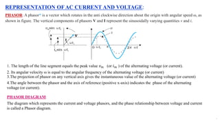
PHASOR: A phasor* is a vector which rotates in the anti clockwise direction about the origin with angular speed ω, as
shown in figure. The vertical components of phasors V and I represent the sinusoidally varying quantities v and i.
1. The length of the line segment equals the peak value 𝑣𝑚 (or 𝑖𝑚 ) of the alternating voltage (or current).
2. Its angular velocity ω is equal to the angular frequency of the alternating voltage (or current)
3.The projection of phasor on any vertical axis gives the instantaneous value of the alternating voltage (or current)
4.The angle between the phasor and the axis of reference (positive x-axis) indicates the phase of the alternating
voltage (or current).
PHASOR DIAGRAM:
The diagram which represents the current and voltage phasors, and the phase relationship between voltage and current
is called a Phasor diagram.
AC VOLTAGE APPLIED TO AN INDUCTOR:
Consider a circuit containing a pure inductor of inductance L connected across an alternating voltage
source 𝜀 as shown in the figure. The alternating voltage is given by the equation
v = 𝒗𝒎 sin ωt (1)
The alternating current flowing through the inductor induces a self-induced emf or back emf in the
circuit which is given by
𝒗′
= − L
𝒅𝒊
𝒅𝒕
(2)
According to Kirchhoff’s (loop rule )voltage law, the algebraic sum of potential differences in a closed circuit is zero
ie, , σ 𝜀 = 0
∴ v − 𝑣′
= 0
(or) 𝑣𝑚 sin ωt − L
𝑑𝑖
𝑑𝑡
= 0
(or) L
𝑑𝑖
𝑑𝑡
= 𝑣𝑚 sin ωt
(or)
𝒅𝒊
𝒅𝒕
=
𝒗𝒎
𝑳
sin ωt (3)
Since current i is a function of time, the slope
𝑑𝑖
𝑑𝑡
must be a sinusoidally varying quantity.Hence, the current in the
circuit is got by integrating equn (3) with respect to time.
‫׬‬
𝑑𝑖
𝑑𝑡
dt =
𝑣𝑚
L
‫׬‬ sin ωt dt
(or) i =
𝑣𝑚
L
−cos ωt
𝜔
+ constant.
where,
𝑣𝑚
𝜔 L
= 𝑖𝑚 = current amplitude ( maximum value of current )
The term 𝜔 L is analogous to resistance and is called as “inductive reactance” ( 𝑋𝐿). It is the
opposition offered by the inductor to the flow of AC.
∴ 𝑋𝐿 = 𝜔 L ( Its unit is ohm )
(or) 𝑋𝐿 = 2 𝜋 𝜐 L
where, 𝜐 → frequency of the applied AC voltage.
Hence, the amplitude of the current is given by 𝑖𝑚 =
𝑣𝑚
𝑋L
Since the current oscillates symmetrically about zero, the time independent component of current is zero.
Hence, the integration constant is zero.
(or) i =
𝑣𝑚
𝜔 L
sin ωt −
π
2
( ∵ −cos ωt = sin ωt −
π
2
)
(or) i = 𝒊𝒎 sin 𝛚𝐭 −
𝝅
𝟐
(4)
For AC, 𝑋𝐿 ∝ 𝜐 (𝑋𝐿 is directly proportional to the frequency )
For DC, 𝜐 = 0. Hence, 𝑋𝐿 = 0. Hence, an ideal inductor offers no resistance to DC current.
From equns (1) and (4), it is found that, the current lags the voltage by a phase angle
𝛑
𝟐
or one quarter of a
cycle.
Phasor diagram voltage versus current graph
We see that the current reaches its maximum value later than voltage by one fourth of a period
T
4
.
Also,
T
4
=
Τ
𝜋
2
𝜔
Instantaneous Power: ( 𝑝𝐿)
The instantaneous power supplied to the inductor is equal to the product of the instantaneous current and instantaneous
voltage.
𝑝𝐿 = i v = 𝑖𝑚 sin ωt −
π
2
× 𝑣𝑚 sin ωt
= 𝑖𝑚 𝑣𝑚 −cos ωt sin ωt
= − 𝑖𝑚 𝑣𝑚 ( cos ωt ) (sin ωt )
=
− 𝑖𝑚 𝑣𝑚
2
( 2 sin ωt cos ωt )
=
− 𝑖𝑚 𝑣𝑚
2
( sin 2 ωt )
So, the average power over one cycle of AC is
PL =
− 𝑖𝑚 𝑣𝑚
2
( sin 2 ωt )
=
− 𝑖𝑚 𝑣𝑚
2
sin 2 ωt
Since sin 2 ωt = 0, PL = 0
Thus, the average power supplied to an inductor over one complete cycle of AC is zero.
AC VOLTAGE APPLIED TO A CAPACITOR:
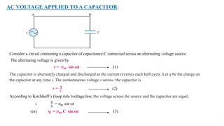
Consider a circuit containing a capacitor of capacitance C connected across an alternating voltage source.
The alternating voltage is given by
v = 𝒗𝒎 sin ωt (1)
The capacitor is alternately charged and discharged as the current reverses each half cycle. Let q be the charge on
the capacitor at any time t. The instantaneous voltage v across the capacitor is
v =
𝒒
𝑪
(2)
According to Kirchhoff’s (loop rule )voltage law, the voltage across the source and the capacitor are equal,
∴
𝑞
C
= 𝑣𝑚 sin ωt
(or) q = 𝒗𝒎 C sin ωt (3)
The instantaneous current in the circuit is given by
i =
𝑑𝑞
𝑑𝑡
=
𝑑
𝑑𝑡
(𝑣𝑚 C sin ωt )
(or) i = 𝑣𝑚 C
𝑑
𝑑𝑡
(sin ωt )
= 𝑣𝑚 C ( cos ωt ) ω
(or) i =
𝑣𝑚
ൗ
1
ωC
cos ωt
(or) i =
𝑣𝑚
ൗ
1
ωC
sin (ωt +
π
2
)
(or) i = 𝒊𝒎 sin (𝛚𝐭 +
𝝅
𝟐
) (4)
where,
𝑣𝑚
ൗ
1
ωC
= 𝑖𝑚 = current amplitude ( maximum value of current )
The term ( Τ
1
ωC ) is analogous to resistance and is called as “capacitive reactance” ( 𝑋C). It is the opposition offered by the
capacitor to the flow of AC.
∴ 𝑋C =
1
ωC
( Its unit is ohm )
(or) 𝑋C =
1
2 𝜋 𝜐 C
where, 𝜐 → frequency of the applied AC voltage.
Hence, the amplitude of the current is given by 𝑖𝑚 =
𝑣𝑚
𝑋C
For AC, 𝑋C ∝
1
𝜐
(𝑋C is inversely proportional to the frequency )
For DC, 𝜐 = 0. Hence, 𝑋C =
1
0
= infinity.
Thus a capacitive circuit offers infinite resistance to the steady current ( DC ). So the steady current ( DC ) cannot flow
through the capacitor.
From equns (1) and (4), it is found that, the current leads the voltage by a phase angle
𝛑
𝟐
or one quarter of a cycle.
Phasor diagram voltage versus current graph
We see that the current reaches its maximum value earlier than voltage by one fourth of a period
T
4
.
Also,
T
4
=
Τ
𝜋
2
𝜔
Instantaneous Power: ( 𝑝C)
The instantaneous power supplied to the capacitor is equal to the product of the instantaneous current and instantaneous
voltage.
𝑝𝑐 = i v = 𝑖𝑚 sin (ωt +
π
2
) × 𝑣𝑚 sin ωt
= 𝑖𝑚 𝑣𝑚 ( cos ωt ) (sin ωt )
=
𝑖𝑚 𝑣𝑚
2
( 2 sin ωt cos ωt )
=
𝑖𝑚 𝑣𝑚
2
( sin 2 ωt )
So, the average power over one cycle of AC is
PC =
𝑖𝑚 𝑣𝑚
2
( sin 2 ωt )
=
𝑖𝑚 𝑣𝑚
2
sin 2 ωt
Since sin 2 ωt = 0, PC = 0
Thus, the average power supplied to a capacitor over one complete cycle of AC is zero.
AC VOLTAGE APPLIED TO A SERIES LCR CIRCUIT:
Consider a circuit containing a resistor of resistance R, an inductor of inductance L and a capacitor of capacitance C
connected across an alternating voltage source 𝜀.
The applied alternating voltage of the source is given by the equation.
v = 𝒗𝒎 sin ωt (1)
Also, v = 𝑣𝐿 + 𝑣𝐶 + 𝑣𝑅
= L
𝒅𝒊
𝒅𝒕
+
𝒒
𝑪
+ i R (2)
To determine the instantaneous current and its phase relationship with applied alternating voltage v,we use the phasor
diagram method.
Phasor Diagram Method:
Since the inductor, capacitor and resistor are connected in series, the current flowing through each element will be the
same at any instant. It is given by
i = 𝒊𝒎 sin (𝛚𝐭 + 𝝓) (3)
where, 𝜙 → phase difference between the voltage across the source and the current in the circuit.
Let I be the phasor representing the current in the circuit.
Let 𝐕𝐑 → voltage across the resistor. (𝐕𝐑 is in phase with I )
Let 𝐕𝐋 → voltage across the inductor. (𝐕𝐋 is ahead of I by
π
2
)
Let 𝐕𝐂 → voltage across the capacitor. (𝐕𝐂 is behind I by
π
2
)
Let V → voltage across the source.
Amplitude(length) of phasor 𝐕𝐑 = 𝑣𝑅𝑚 = 𝑖𝑚 R
Amplitude(length) of phasor 𝐕𝐋 = 𝑣𝐿𝑚 = 𝑖𝑚 𝑋L
Amplitude(length) of phasor 𝐕𝐂 = 𝑣𝐶𝑚
= 𝑖𝑚 𝑋C
The voltage equation for the LCR circuit is
v = 𝒗𝑳 + 𝒗𝑪 + 𝒗𝑹 (4)
The phasor relation is V = 𝐕𝐋 + 𝐕𝐑 + 𝐕𝐂 (5)
Let the circuit be effectively capacitive, ie, 𝐕𝐂 > 𝐕𝐋
𝐕𝐂 and 𝐕𝐋 are always along the same line and in opposite directions. They can be combined into a
single phasor 𝐕𝐂 + 𝐕𝐋which has a magnitude 𝑣𝐶 𝑚 − 𝑣𝐿 𝑚 .
Since V is represented as the hypotenuse of a right-triangle whose sides are 𝐕𝐑 and ( 𝐕𝐂 + 𝐕𝐋 ),
then from Pythagorean theorem,
𝒗𝒎
𝟐
= 𝒗𝑹 𝒎
𝟐
+ ( 𝒗𝑪 𝒎 − 𝒗𝑳 𝒎 )𝟐
(6)
Substituting 𝑣𝑅 𝑚 = 𝑖𝑚 R, 𝑣𝐶 𝑚 = 𝑖𝑚 𝑋C and 𝑣𝐿 𝑚 = 𝑖𝑚 𝑋L, we get
𝑣𝑚
2
= (𝑖𝑚 R)2
+ ( 𝑖𝑚 𝑋C − 𝑖𝑚 𝑋L )2
= 𝑖𝑚
2
𝑅2
+ ( 𝑋C − 𝑋L )2
(or) 𝒗𝒎 = 𝒊𝒎 𝑹𝟐 + ( 𝑿𝑪 − 𝑿𝑳 )𝟐 (7)
∴ 𝒊𝒎 =
𝒗𝒎
𝑹𝟐 + ( 𝑿𝑪 − 𝑿𝑳 )𝟐
(8)
Comparing equn (8) with Ohm’s law, it is found that the factor 𝑅2 + ( 𝑋C − 𝑋L )2 plays the role
of resistance. This effective opposition offered by the series LCR circuit to the flow of AC is called
impedance ( Z )
∴ 𝒊𝒎 =
𝒗𝒎
𝒁
(9)
and Z = 𝑹𝟐 + ( 𝑿𝑪 − 𝑿𝑳 )𝟐 (10)
Since phasor I is always parallel to phasor 𝐕𝐑 , the phase angle 𝜙 is the angle between 𝐕𝐑 and V .
It can be determined from the following impedance diagram.
tan 𝝓 =
( 𝑿𝑪 − 𝑿𝑳 )
𝑹
(11)
Also, tan 𝝓 =
( 𝒗𝑪 𝒎 − 𝒗𝑳 𝒎 )
𝒗𝑹𝒎
(12)
If 𝑋C > 𝑋L, then 𝜙 is positive and the circuit is predominantly capacitive.
If 𝑋C < 𝑋L, then 𝜙 is negative and the circuit is predominantly inductive.
If 𝑋C = 𝑋L, then 𝜙 = 0. Voltage and Current are in phase with each other.
The phasor diagram and variation of v and i with ωt for an arbitrary time 𝑡1 , for the case 𝑋C > 𝑋L is
shown below .
The solution so obtained by drawing phasor diagram is called ‘steady state solution’.
BIBLIOGRAPHY: PREPARED BY:
I acknowledge that the contents are P.SARAVANAN
taken from NCERT Text book in PGT ( SS )
Physics for class XII ( 2020-21) AECS, MYSORE
END OF PPT-1
IN
ALTERNATING CURRENT

More Related Content

Similar to PowerPoint Presentation.pdf

1.1 Generation of alternating voltage, phasor representation of sinusoidal qu...
1.1 Generation of alternating voltage, phasor representation of sinusoidal qu...1.1 Generation of alternating voltage, phasor representation of sinusoidal qu...
1.1 Generation of alternating voltage, phasor representation of sinusoidal qu...
KrishnaKorankar
 
Alternating Current
Alternating CurrentAlternating Current
Alternating Current
Priyanka Jakhar
 
Alternating Current Lecture Introduction
Alternating Current Lecture IntroductionAlternating Current Lecture Introduction
Alternating Current Lecture Introduction
xdarlord
 
AC_CIRCUITS[1].pptx
AC_CIRCUITS[1].pptxAC_CIRCUITS[1].pptx
AC_CIRCUITS[1].pptx
srikanthreddyn111
 
lecture note AC fundamental LESSON 2.pptx
lecture note AC fundamental LESSON 2.pptxlecture note AC fundamental LESSON 2.pptx
lecture note AC fundamental LESSON 2.pptx
kifle203
 
ACCircuits1pptx__2022_12_27_17_30_19.pptx
ACCircuits1pptx__2022_12_27_17_30_19.pptxACCircuits1pptx__2022_12_27_17_30_19.pptx
ACCircuits1pptx__2022_12_27_17_30_19.pptx
vekariyakashyap
 
Chameli Devi Group of Institution(BEE) (2).pptx
Chameli Devi Group of Institution(BEE) (2).pptxChameli Devi Group of Institution(BEE) (2).pptx
Chameli Devi Group of Institution(BEE) (2).pptx
10croreviews
 
Circuit theory mt
Circuit theory mtCircuit theory mt
Circuit theory mtjerbor
 
Circuit theory mt
Circuit theory mtCircuit theory mt
Circuit theory mt
jerbor
 
AC FUNDAMENTALS.pptx
AC FUNDAMENTALS.pptxAC FUNDAMENTALS.pptx
AC FUNDAMENTALS.pptx
roshan375533
 
AC circuit
AC circuitAC circuit
AC circuit
RAVINDRA CHANDEL
 
ac circuit
ac circuitac circuit
ac circuit
Yasir Hashmi
 
AC.pptx
AC.pptxAC.pptx
AC.pptx
xdarlord
 
Electrical Engineering
Electrical EngineeringElectrical Engineering
Electrical Engineering
Ekeeda
 
Alternating Current
Alternating CurrentAlternating Current
Alternating Current
Mayank Pandey
 
Short question on basic elelctrical
Short question on basic elelctricalShort question on basic elelctrical
Short question on basic elelctrical
Bhawnachauhan8
 
DC AC.pptx
DC AC.pptxDC AC.pptx
DC AC.pptx
KubaOrszulak
 
HVac transmssion lines systems.ppt
HVac transmssion lines systems.pptHVac transmssion lines systems.ppt
HVac transmssion lines systems.ppt
abidSherazi
 
Introduction to Alternating Currents AC Circuits
Introduction to Alternating Currents AC CircuitsIntroduction to Alternating Currents AC Circuits
Introduction to Alternating Currents AC Circuits
xdarlord
 
Lecture 7 ac waves
Lecture 7 ac wavesLecture 7 ac waves
Lecture 7 ac waves
Mohamed Jama
 

Similar to PowerPoint Presentation.pdf (20)

1.1 Generation of alternating voltage, phasor representation of sinusoidal qu...
1.1 Generation of alternating voltage, phasor representation of sinusoidal qu...1.1 Generation of alternating voltage, phasor representation of sinusoidal qu...
1.1 Generation of alternating voltage, phasor representation of sinusoidal qu...
 
Alternating Current
Alternating CurrentAlternating Current
Alternating Current
 
Alternating Current Lecture Introduction
Alternating Current Lecture IntroductionAlternating Current Lecture Introduction
Alternating Current Lecture Introduction
 
AC_CIRCUITS[1].pptx
AC_CIRCUITS[1].pptxAC_CIRCUITS[1].pptx
AC_CIRCUITS[1].pptx
 
lecture note AC fundamental LESSON 2.pptx
lecture note AC fundamental LESSON 2.pptxlecture note AC fundamental LESSON 2.pptx
lecture note AC fundamental LESSON 2.pptx
 
ACCircuits1pptx__2022_12_27_17_30_19.pptx
ACCircuits1pptx__2022_12_27_17_30_19.pptxACCircuits1pptx__2022_12_27_17_30_19.pptx
ACCircuits1pptx__2022_12_27_17_30_19.pptx
 
Chameli Devi Group of Institution(BEE) (2).pptx
Chameli Devi Group of Institution(BEE) (2).pptxChameli Devi Group of Institution(BEE) (2).pptx
Chameli Devi Group of Institution(BEE) (2).pptx
 
Circuit theory mt
Circuit theory mtCircuit theory mt
Circuit theory mt
 
Circuit theory mt
Circuit theory mtCircuit theory mt
Circuit theory mt
 
AC FUNDAMENTALS.pptx
AC FUNDAMENTALS.pptxAC FUNDAMENTALS.pptx
AC FUNDAMENTALS.pptx
 
AC circuit
AC circuitAC circuit
AC circuit
 
ac circuit
ac circuitac circuit
ac circuit
 
AC.pptx
AC.pptxAC.pptx
AC.pptx
 
Electrical Engineering
Electrical EngineeringElectrical Engineering
Electrical Engineering
 
Alternating Current
Alternating CurrentAlternating Current
Alternating Current
 
Short question on basic elelctrical
Short question on basic elelctricalShort question on basic elelctrical
Short question on basic elelctrical
 
DC AC.pptx
DC AC.pptxDC AC.pptx
DC AC.pptx
 
HVac transmssion lines systems.ppt
HVac transmssion lines systems.pptHVac transmssion lines systems.ppt
HVac transmssion lines systems.ppt
 
Introduction to Alternating Currents AC Circuits
Introduction to Alternating Currents AC CircuitsIntroduction to Alternating Currents AC Circuits
Introduction to Alternating Currents AC Circuits
 
Lecture 7 ac waves
Lecture 7 ac wavesLecture 7 ac waves
Lecture 7 ac waves
 

Recently uploaded

Immunizing Image Classifiers Against Localized Adversary Attacks
Immunizing Image Classifiers Against Localized Adversary AttacksImmunizing Image Classifiers Against Localized Adversary Attacks
Immunizing Image Classifiers Against Localized Adversary Attacks
gerogepatton
 
AKS UNIVERSITY Satna Final Year Project By OM Hardaha.pdf
AKS UNIVERSITY Satna Final Year Project By OM Hardaha.pdfAKS UNIVERSITY Satna Final Year Project By OM Hardaha.pdf
AKS UNIVERSITY Satna Final Year Project By OM Hardaha.pdf
SamSarthak3
 
一比一原版(IIT毕业证)伊利诺伊理工大学毕业证成绩单专业办理
一比一原版(IIT毕业证)伊利诺伊理工大学毕业证成绩单专业办理一比一原版(IIT毕业证)伊利诺伊理工大学毕业证成绩单专业办理
一比一原版(IIT毕业证)伊利诺伊理工大学毕业证成绩单专业办理
zwunae
 
road safety engineering r s e unit 3.pdf
road safety engineering  r s e unit 3.pdfroad safety engineering  r s e unit 3.pdf
road safety engineering r s e unit 3.pdf
VENKATESHvenky89705
 
Gen AI Study Jams _ For the GDSC Leads in India.pdf
Gen AI Study Jams _ For the GDSC Leads in India.pdfGen AI Study Jams _ For the GDSC Leads in India.pdf
Gen AI Study Jams _ For the GDSC Leads in India.pdf
gdsczhcet
 
Water Industry Process Automation and Control Monthly - May 2024.pdf
Water Industry Process Automation and Control Monthly - May 2024.pdfWater Industry Process Automation and Control Monthly - May 2024.pdf
Water Industry Process Automation and Control Monthly - May 2024.pdf
Water Industry Process Automation & Control
 
Student information management system project report ii.pdf
Student information management system project report ii.pdfStudent information management system project report ii.pdf
Student information management system project report ii.pdf
Kamal Acharya
 
Runway Orientation Based on the Wind Rose Diagram.pptx
Runway Orientation Based on the Wind Rose Diagram.pptxRunway Orientation Based on the Wind Rose Diagram.pptx
Runway Orientation Based on the Wind Rose Diagram.pptx
SupreethSP4
 
Railway Signalling Principles Edition 3.pdf
Railway Signalling Principles Edition 3.pdfRailway Signalling Principles Edition 3.pdf
Railway Signalling Principles Edition 3.pdf
TeeVichai
 
space technology lecture notes on satellite
space technology lecture notes on satellitespace technology lecture notes on satellite
space technology lecture notes on satellite
ongomchris
 
一比一原版(UofT毕业证)多伦多大学毕业证成绩单如何办理
一比一原版(UofT毕业证)多伦多大学毕业证成绩单如何办理一比一原版(UofT毕业证)多伦多大学毕业证成绩单如何办理
一比一原版(UofT毕业证)多伦多大学毕业证成绩单如何办理
ydteq
 
Investor-Presentation-Q1FY2024 investor presentation document.pptx
Investor-Presentation-Q1FY2024 investor presentation document.pptxInvestor-Presentation-Q1FY2024 investor presentation document.pptx
Investor-Presentation-Q1FY2024 investor presentation document.pptx
AmarGB2
 
Planning Of Procurement o different goods and services
Planning Of Procurement o different goods and servicesPlanning Of Procurement o different goods and services
Planning Of Procurement o different goods and services
JoytuBarua2
 
ethical hacking in wireless-hacking1.ppt
ethical hacking in wireless-hacking1.pptethical hacking in wireless-hacking1.ppt
ethical hacking in wireless-hacking1.ppt
Jayaprasanna4
 
HYDROPOWER - Hydroelectric power generation
HYDROPOWER - Hydroelectric power generationHYDROPOWER - Hydroelectric power generation
HYDROPOWER - Hydroelectric power generation
Robbie Edward Sayers
 
一比一原版(SFU毕业证)西蒙菲莎大学毕业证成绩单如何办理
一比一原版(SFU毕业证)西蒙菲莎大学毕业证成绩单如何办理一比一原版(SFU毕业证)西蒙菲莎大学毕业证成绩单如何办理
一比一原版(SFU毕业证)西蒙菲莎大学毕业证成绩单如何办理
bakpo1
 
English lab ppt no titlespecENG PPTt.pdf
English lab ppt no titlespecENG PPTt.pdfEnglish lab ppt no titlespecENG PPTt.pdf
English lab ppt no titlespecENG PPTt.pdf
BrazilAccount1
 
ML for identifying fraud using open blockchain data.pptx
ML for identifying fraud using open blockchain data.pptxML for identifying fraud using open blockchain data.pptx
ML for identifying fraud using open blockchain data.pptx
Vijay Dialani, PhD
 
WATER CRISIS and its solutions-pptx 1234
WATER CRISIS and its solutions-pptx 1234WATER CRISIS and its solutions-pptx 1234
WATER CRISIS and its solutions-pptx 1234
AafreenAbuthahir2
 
RAT: Retrieval Augmented Thoughts Elicit Context-Aware Reasoning in Long-Hori...
RAT: Retrieval Augmented Thoughts Elicit Context-Aware Reasoning in Long-Hori...RAT: Retrieval Augmented Thoughts Elicit Context-Aware Reasoning in Long-Hori...
RAT: Retrieval Augmented Thoughts Elicit Context-Aware Reasoning in Long-Hori...
thanhdowork
 

Recently uploaded (20)

Immunizing Image Classifiers Against Localized Adversary Attacks
Immunizing Image Classifiers Against Localized Adversary AttacksImmunizing Image Classifiers Against Localized Adversary Attacks
Immunizing Image Classifiers Against Localized Adversary Attacks
 
AKS UNIVERSITY Satna Final Year Project By OM Hardaha.pdf
AKS UNIVERSITY Satna Final Year Project By OM Hardaha.pdfAKS UNIVERSITY Satna Final Year Project By OM Hardaha.pdf
AKS UNIVERSITY Satna Final Year Project By OM Hardaha.pdf
 
一比一原版(IIT毕业证)伊利诺伊理工大学毕业证成绩单专业办理
一比一原版(IIT毕业证)伊利诺伊理工大学毕业证成绩单专业办理一比一原版(IIT毕业证)伊利诺伊理工大学毕业证成绩单专业办理
一比一原版(IIT毕业证)伊利诺伊理工大学毕业证成绩单专业办理
 
road safety engineering r s e unit 3.pdf
road safety engineering  r s e unit 3.pdfroad safety engineering  r s e unit 3.pdf
road safety engineering r s e unit 3.pdf
 
Gen AI Study Jams _ For the GDSC Leads in India.pdf
Gen AI Study Jams _ For the GDSC Leads in India.pdfGen AI Study Jams _ For the GDSC Leads in India.pdf
Gen AI Study Jams _ For the GDSC Leads in India.pdf
 
Water Industry Process Automation and Control Monthly - May 2024.pdf
Water Industry Process Automation and Control Monthly - May 2024.pdfWater Industry Process Automation and Control Monthly - May 2024.pdf
Water Industry Process Automation and Control Monthly - May 2024.pdf
 
Student information management system project report ii.pdf
Student information management system project report ii.pdfStudent information management system project report ii.pdf
Student information management system project report ii.pdf
 
Runway Orientation Based on the Wind Rose Diagram.pptx
Runway Orientation Based on the Wind Rose Diagram.pptxRunway Orientation Based on the Wind Rose Diagram.pptx
Runway Orientation Based on the Wind Rose Diagram.pptx
 
Railway Signalling Principles Edition 3.pdf
Railway Signalling Principles Edition 3.pdfRailway Signalling Principles Edition 3.pdf
Railway Signalling Principles Edition 3.pdf
 
space technology lecture notes on satellite
space technology lecture notes on satellitespace technology lecture notes on satellite
space technology lecture notes on satellite
 
一比一原版(UofT毕业证)多伦多大学毕业证成绩单如何办理
一比一原版(UofT毕业证)多伦多大学毕业证成绩单如何办理一比一原版(UofT毕业证)多伦多大学毕业证成绩单如何办理
一比一原版(UofT毕业证)多伦多大学毕业证成绩单如何办理
 
Investor-Presentation-Q1FY2024 investor presentation document.pptx
Investor-Presentation-Q1FY2024 investor presentation document.pptxInvestor-Presentation-Q1FY2024 investor presentation document.pptx
Investor-Presentation-Q1FY2024 investor presentation document.pptx
 
Planning Of Procurement o different goods and services
Planning Of Procurement o different goods and servicesPlanning Of Procurement o different goods and services
Planning Of Procurement o different goods and services
 
ethical hacking in wireless-hacking1.ppt
ethical hacking in wireless-hacking1.pptethical hacking in wireless-hacking1.ppt
ethical hacking in wireless-hacking1.ppt
 
HYDROPOWER - Hydroelectric power generation
HYDROPOWER - Hydroelectric power generationHYDROPOWER - Hydroelectric power generation
HYDROPOWER - Hydroelectric power generation
 
一比一原版(SFU毕业证)西蒙菲莎大学毕业证成绩单如何办理
一比一原版(SFU毕业证)西蒙菲莎大学毕业证成绩单如何办理一比一原版(SFU毕业证)西蒙菲莎大学毕业证成绩单如何办理
一比一原版(SFU毕业证)西蒙菲莎大学毕业证成绩单如何办理
 
English lab ppt no titlespecENG PPTt.pdf
English lab ppt no titlespecENG PPTt.pdfEnglish lab ppt no titlespecENG PPTt.pdf
English lab ppt no titlespecENG PPTt.pdf
 
ML for identifying fraud using open blockchain data.pptx
ML for identifying fraud using open blockchain data.pptxML for identifying fraud using open blockchain data.pptx
ML for identifying fraud using open blockchain data.pptx
 
WATER CRISIS and its solutions-pptx 1234
WATER CRISIS and its solutions-pptx 1234WATER CRISIS and its solutions-pptx 1234
WATER CRISIS and its solutions-pptx 1234
 
RAT: Retrieval Augmented Thoughts Elicit Context-Aware Reasoning in Long-Hori...
RAT: Retrieval Augmented Thoughts Elicit Context-Aware Reasoning in Long-Hori...RAT: Retrieval Augmented Thoughts Elicit Context-Aware Reasoning in Long-Hori...
RAT: Retrieval Augmented Thoughts Elicit Context-Aware Reasoning in Long-Hori...
 

PowerPoint Presentation.pdf

  • 1. ATOMIC ENERGY CENTRAL SCHOOL, MYSORE DISTANT LEARNING PROGRAM 2020-21 CHAPTER-7 ALTERNATING CURRENT PPT- (1 of 2 ) PREPARED BY: P.SARAVANAN
  • 2. INTRODUCTION: An alternating voltage is the voltage which changes polarity at regular intervals of time and the direction of the resulting alternating current also changes accordingly. If the wave form of alternating voltage is a sine wave, then it is known as “ sinusoidal alternating voltage ”. It is given by v = 𝒗𝒎 sin ωt where, v → instantaneous value of alternating voltage 𝑣𝑚 → voltage amplitude (or) maximum value of alternating voltage ω → angular frequency of alternating voltage When sinusoidal alternating voltage is applied to a closed circuit, the resulting current also is sinusoidal in nature. It is given by the relation i = 𝒊𝒎 sin ωt where, i → instantaneous value of alternating current 𝑖𝑚 → current amplitude (or) maximum value of alternating current ω → angular frequency of alternating current
  • 3. The direction of sinusoidal voltage or current is reversed after every half-cycle and its magnitude is also changing continuously as shown in figure below. Alternating voltage Alternating current
  • 4. MEAN (OR) AVERAGE VALUE OF AC: ( 𝑖𝑎𝑣 ) Alternating current in a circuit changes from one instant to another instant and its direction also reverses for every half cycle. During positive half cycle, current is taken as positive and during negative half cycle, current is taken as negative. Therefore, the mean value or average value of alternating current over one complete cycle is zero. Therefore, the average or mean value of AC is measured over one half of cycle. DEFINITION: Average value of alternating current is defined as the average of all values of current over a positive half cycle or negative half cycle. It can be shown that 𝑖𝑎𝑣 = 0.637 𝑖𝑚 for positive half cycle and 𝑖𝑎𝑣 = − 0.637 𝑖𝑚 for negative half cycle
  • 5. RMS value of AC: ( 𝐼𝑟𝑚𝑠 ) Root Mean Square value of AC is defined as the square root of the mean value of the squares of all currents over one cycle. 𝑰𝒓𝒎𝒔 = 𝒊𝟏 𝟐 + 𝒊𝟐 𝟐 + ...+ 𝒊𝒏 𝟐 𝒏 It is also defined as that value of the steady current (DC), which when passed through a resistor for a given time, will generate the same amount of heat as generated by an alternating current when passed through the same resistor for the same time. It is also called as “ effective value of AC ” ( 𝐼𝑒𝑓𝑓 ) or ( I ) It can be shown that, 𝑰𝒓𝒎𝒔 = 𝒊𝒎 𝟐 = 0.707 𝒊𝒎 ie, rms value of AC = 70.7 % of current amplitude Similarly, 𝑽𝒓𝒎𝒔 = 𝒗𝒎 𝟐 = 0.707 𝒗𝒎
  • 6. AC VOLTAGE APPLIED TO A RESISTOR: Let an alternating source of potential difference ( 𝜀 ) be connected across a resistor of resistance R. The instantaneous value of the applied potential difference is given by v = 𝒗𝒎 sin ωt (1) where, 𝑣𝑚 → voltage amplitude of the oscillating potential difference ω → angular frequency of oscillating potential difference An alternating current i flowing in the circuit due to this voltage, develops a potential drop across R and is given by v = i R (2)
  • 7. According to Kirchhoff’s (loop rule )voltage law, the algebraic sum of potential differences in a closed circuit is zero. σ 𝜀 = 0 i R = 𝑣𝑚 sin ωt (or) i = 𝑣𝑚 R sin ωt (or) i = 𝒊𝒎 sin ωt (3) where, 𝑖𝑚 = 𝑣𝑚 R = current amplitude ( From Ohm’s law ) From equations (1) and (3) , it is found that the current and voltage reach their maximum value, minimum value and zero value simultaneously. Hence, current and voltage are in phase with each other.
  • 8. The sum of the instantaneous current values over one complete cycle is zero, and the average current over one cycle of AC is zero. But the sum of the squares of all currents over one cycle is not zero. Since 𝑖2 is always positive, irrespective of whether i is positive or negative, Joule heating and dissipation of electrical energy takes place when an ac current passes through a resistor. The instantaneous power dissipated in the resistor is given by p = 𝑖2 R = ( 𝑖𝑚 sin ωt )2 R = 𝑖𝑚 2 R sin2 ωt The average power over a cycle of AC is ഥ 𝒑 = 𝒊𝟐 𝑹 = 𝒊𝒎 𝟐 𝐑 𝒔𝒊𝒏𝟐 𝝎𝒕 (4) Since 𝑖𝑚 2 and R are constants, ҧ 𝑝 = 𝑖𝑚 2 R sin2 ωt
  • 9. But, sin2 ωt = 1 – cos 2 ωt 2 = 1 2 – cos 2 ωt 2 Since cos 2 ωt = 0 Hence, sin2 ωt = 1 2 ∴ ഥ 𝒑 = 𝒊𝒎 𝟐 𝑹 𝟐 (5) The same amount of DC power ( P = I2𝑅 ) will be dissipated ,if a current equal to 𝐼𝑟𝑚𝑠 or I flows through the resistor R. ∴ P = 𝑰𝒓𝒎𝒔 𝟐 R (6)
  • 10. But, P = ҧ 𝑝 𝐼𝑟𝑚𝑠 2 R = 𝑖𝑚 2 R 2 𝐼𝑟𝑚𝑠 2 = 𝑖𝑚 2 2 (or) I = 𝑰𝒓𝒎𝒔 = 𝒊𝒎 𝟐 = 0.707 𝒊𝒎 (7) Similarly, RMS value of voltage or effective value of voltage is given by V = 𝑽𝒓𝒎𝒔 = 𝒗𝒎 𝟐 = 0.707 𝒗𝒎 (8)
  • 11. REPRESENTATION OFAC CURRENT AND VOLTAGE: PHASOR: A phasor* is a vector which rotates in the anti clockwise direction about the origin with angular speed ω, as shown in figure. The vertical components of phasors V and I represent the sinusoidally varying quantities v and i. 1. The length of the line segment equals the peak value 𝑣𝑚 (or 𝑖𝑚 ) of the alternating voltage (or current). 2. Its angular velocity ω is equal to the angular frequency of the alternating voltage (or current) 3.The projection of phasor on any vertical axis gives the instantaneous value of the alternating voltage (or current) 4.The angle between the phasor and the axis of reference (positive x-axis) indicates the phase of the alternating voltage (or current). PHASOR DIAGRAM: The diagram which represents the current and voltage phasors, and the phase relationship between voltage and current is called a Phasor diagram.
  • 12. AC VOLTAGE APPLIED TO AN INDUCTOR: Consider a circuit containing a pure inductor of inductance L connected across an alternating voltage source 𝜀 as shown in the figure. The alternating voltage is given by the equation v = 𝒗𝒎 sin ωt (1) The alternating current flowing through the inductor induces a self-induced emf or back emf in the circuit which is given by 𝒗′ = − L 𝒅𝒊 𝒅𝒕 (2)
  • 13. According to Kirchhoff’s (loop rule )voltage law, the algebraic sum of potential differences in a closed circuit is zero ie, , σ 𝜀 = 0 ∴ v − 𝑣′ = 0 (or) 𝑣𝑚 sin ωt − L 𝑑𝑖 𝑑𝑡 = 0 (or) L 𝑑𝑖 𝑑𝑡 = 𝑣𝑚 sin ωt (or) 𝒅𝒊 𝒅𝒕 = 𝒗𝒎 𝑳 sin ωt (3) Since current i is a function of time, the slope 𝑑𝑖 𝑑𝑡 must be a sinusoidally varying quantity.Hence, the current in the circuit is got by integrating equn (3) with respect to time. ‫׬‬ 𝑑𝑖 𝑑𝑡 dt = 𝑣𝑚 L ‫׬‬ sin ωt dt (or) i = 𝑣𝑚 L −cos ωt 𝜔 + constant.
  • 14. where, 𝑣𝑚 𝜔 L = 𝑖𝑚 = current amplitude ( maximum value of current ) The term 𝜔 L is analogous to resistance and is called as “inductive reactance” ( 𝑋𝐿). It is the opposition offered by the inductor to the flow of AC. ∴ 𝑋𝐿 = 𝜔 L ( Its unit is ohm ) (or) 𝑋𝐿 = 2 𝜋 𝜐 L where, 𝜐 → frequency of the applied AC voltage. Hence, the amplitude of the current is given by 𝑖𝑚 = 𝑣𝑚 𝑋L Since the current oscillates symmetrically about zero, the time independent component of current is zero. Hence, the integration constant is zero. (or) i = 𝑣𝑚 𝜔 L sin ωt − π 2 ( ∵ −cos ωt = sin ωt − π 2 ) (or) i = 𝒊𝒎 sin 𝛚𝐭 − 𝝅 𝟐 (4)
  • 15. For AC, 𝑋𝐿 ∝ 𝜐 (𝑋𝐿 is directly proportional to the frequency ) For DC, 𝜐 = 0. Hence, 𝑋𝐿 = 0. Hence, an ideal inductor offers no resistance to DC current. From equns (1) and (4), it is found that, the current lags the voltage by a phase angle 𝛑 𝟐 or one quarter of a cycle. Phasor diagram voltage versus current graph We see that the current reaches its maximum value later than voltage by one fourth of a period T 4 . Also, T 4 = Τ 𝜋 2 𝜔
  • 16. Instantaneous Power: ( 𝑝𝐿) The instantaneous power supplied to the inductor is equal to the product of the instantaneous current and instantaneous voltage. 𝑝𝐿 = i v = 𝑖𝑚 sin ωt − π 2 × 𝑣𝑚 sin ωt = 𝑖𝑚 𝑣𝑚 −cos ωt sin ωt = − 𝑖𝑚 𝑣𝑚 ( cos ωt ) (sin ωt ) = − 𝑖𝑚 𝑣𝑚 2 ( 2 sin ωt cos ωt ) = − 𝑖𝑚 𝑣𝑚 2 ( sin 2 ωt ) So, the average power over one cycle of AC is PL = − 𝑖𝑚 𝑣𝑚 2 ( sin 2 ωt ) = − 𝑖𝑚 𝑣𝑚 2 sin 2 ωt Since sin 2 ωt = 0, PL = 0 Thus, the average power supplied to an inductor over one complete cycle of AC is zero.
  • 17. AC VOLTAGE APPLIED TO A CAPACITOR: Consider a circuit containing a capacitor of capacitance C connected across an alternating voltage source. The alternating voltage is given by v = 𝒗𝒎 sin ωt (1) The capacitor is alternately charged and discharged as the current reverses each half cycle. Let q be the charge on the capacitor at any time t. The instantaneous voltage v across the capacitor is v = 𝒒 𝑪 (2) According to Kirchhoff’s (loop rule )voltage law, the voltage across the source and the capacitor are equal, ∴ 𝑞 C = 𝑣𝑚 sin ωt (or) q = 𝒗𝒎 C sin ωt (3)
  • 18. The instantaneous current in the circuit is given by i = 𝑑𝑞 𝑑𝑡 = 𝑑 𝑑𝑡 (𝑣𝑚 C sin ωt ) (or) i = 𝑣𝑚 C 𝑑 𝑑𝑡 (sin ωt ) = 𝑣𝑚 C ( cos ωt ) ω (or) i = 𝑣𝑚 ൗ 1 ωC cos ωt (or) i = 𝑣𝑚 ൗ 1 ωC sin (ωt + π 2 ) (or) i = 𝒊𝒎 sin (𝛚𝐭 + 𝝅 𝟐 ) (4) where, 𝑣𝑚 ൗ 1 ωC = 𝑖𝑚 = current amplitude ( maximum value of current ) The term ( Τ 1 ωC ) is analogous to resistance and is called as “capacitive reactance” ( 𝑋C). It is the opposition offered by the capacitor to the flow of AC. ∴ 𝑋C = 1 ωC ( Its unit is ohm ) (or) 𝑋C = 1 2 𝜋 𝜐 C where, 𝜐 → frequency of the applied AC voltage. Hence, the amplitude of the current is given by 𝑖𝑚 = 𝑣𝑚 𝑋C
  • 19. For AC, 𝑋C ∝ 1 𝜐 (𝑋C is inversely proportional to the frequency ) For DC, 𝜐 = 0. Hence, 𝑋C = 1 0 = infinity. Thus a capacitive circuit offers infinite resistance to the steady current ( DC ). So the steady current ( DC ) cannot flow through the capacitor. From equns (1) and (4), it is found that, the current leads the voltage by a phase angle 𝛑 𝟐 or one quarter of a cycle. Phasor diagram voltage versus current graph We see that the current reaches its maximum value earlier than voltage by one fourth of a period T 4 . Also, T 4 = Τ 𝜋 2 𝜔
  • 20. Instantaneous Power: ( 𝑝C) The instantaneous power supplied to the capacitor is equal to the product of the instantaneous current and instantaneous voltage. 𝑝𝑐 = i v = 𝑖𝑚 sin (ωt + π 2 ) × 𝑣𝑚 sin ωt = 𝑖𝑚 𝑣𝑚 ( cos ωt ) (sin ωt ) = 𝑖𝑚 𝑣𝑚 2 ( 2 sin ωt cos ωt ) = 𝑖𝑚 𝑣𝑚 2 ( sin 2 ωt ) So, the average power over one cycle of AC is PC = 𝑖𝑚 𝑣𝑚 2 ( sin 2 ωt ) = 𝑖𝑚 𝑣𝑚 2 sin 2 ωt Since sin 2 ωt = 0, PC = 0 Thus, the average power supplied to a capacitor over one complete cycle of AC is zero.
  • 21. AC VOLTAGE APPLIED TO A SERIES LCR CIRCUIT: Consider a circuit containing a resistor of resistance R, an inductor of inductance L and a capacitor of capacitance C connected across an alternating voltage source 𝜀. The applied alternating voltage of the source is given by the equation. v = 𝒗𝒎 sin ωt (1) Also, v = 𝑣𝐿 + 𝑣𝐶 + 𝑣𝑅 = L 𝒅𝒊 𝒅𝒕 + 𝒒 𝑪 + i R (2) To determine the instantaneous current and its phase relationship with applied alternating voltage v,we use the phasor diagram method.
  • 22. Phasor Diagram Method: Since the inductor, capacitor and resistor are connected in series, the current flowing through each element will be the same at any instant. It is given by i = 𝒊𝒎 sin (𝛚𝐭 + 𝝓) (3) where, 𝜙 → phase difference between the voltage across the source and the current in the circuit. Let I be the phasor representing the current in the circuit. Let 𝐕𝐑 → voltage across the resistor. (𝐕𝐑 is in phase with I ) Let 𝐕𝐋 → voltage across the inductor. (𝐕𝐋 is ahead of I by π 2 ) Let 𝐕𝐂 → voltage across the capacitor. (𝐕𝐂 is behind I by π 2 ) Let V → voltage across the source.
  • 23. Amplitude(length) of phasor 𝐕𝐑 = 𝑣𝑅𝑚 = 𝑖𝑚 R Amplitude(length) of phasor 𝐕𝐋 = 𝑣𝐿𝑚 = 𝑖𝑚 𝑋L Amplitude(length) of phasor 𝐕𝐂 = 𝑣𝐶𝑚 = 𝑖𝑚 𝑋C The voltage equation for the LCR circuit is v = 𝒗𝑳 + 𝒗𝑪 + 𝒗𝑹 (4) The phasor relation is V = 𝐕𝐋 + 𝐕𝐑 + 𝐕𝐂 (5)
  • 24. Let the circuit be effectively capacitive, ie, 𝐕𝐂 > 𝐕𝐋 𝐕𝐂 and 𝐕𝐋 are always along the same line and in opposite directions. They can be combined into a single phasor 𝐕𝐂 + 𝐕𝐋which has a magnitude 𝑣𝐶 𝑚 − 𝑣𝐿 𝑚 . Since V is represented as the hypotenuse of a right-triangle whose sides are 𝐕𝐑 and ( 𝐕𝐂 + 𝐕𝐋 ), then from Pythagorean theorem, 𝒗𝒎 𝟐 = 𝒗𝑹 𝒎 𝟐 + ( 𝒗𝑪 𝒎 − 𝒗𝑳 𝒎 )𝟐 (6) Substituting 𝑣𝑅 𝑚 = 𝑖𝑚 R, 𝑣𝐶 𝑚 = 𝑖𝑚 𝑋C and 𝑣𝐿 𝑚 = 𝑖𝑚 𝑋L, we get 𝑣𝑚 2 = (𝑖𝑚 R)2 + ( 𝑖𝑚 𝑋C − 𝑖𝑚 𝑋L )2 = 𝑖𝑚 2 𝑅2 + ( 𝑋C − 𝑋L )2 (or) 𝒗𝒎 = 𝒊𝒎 𝑹𝟐 + ( 𝑿𝑪 − 𝑿𝑳 )𝟐 (7) ∴ 𝒊𝒎 = 𝒗𝒎 𝑹𝟐 + ( 𝑿𝑪 − 𝑿𝑳 )𝟐 (8) Comparing equn (8) with Ohm’s law, it is found that the factor 𝑅2 + ( 𝑋C − 𝑋L )2 plays the role of resistance. This effective opposition offered by the series LCR circuit to the flow of AC is called impedance ( Z ) ∴ 𝒊𝒎 = 𝒗𝒎 𝒁 (9) and Z = 𝑹𝟐 + ( 𝑿𝑪 − 𝑿𝑳 )𝟐 (10)
  • 25. Since phasor I is always parallel to phasor 𝐕𝐑 , the phase angle 𝜙 is the angle between 𝐕𝐑 and V . It can be determined from the following impedance diagram. tan 𝝓 = ( 𝑿𝑪 − 𝑿𝑳 ) 𝑹 (11) Also, tan 𝝓 = ( 𝒗𝑪 𝒎 − 𝒗𝑳 𝒎 ) 𝒗𝑹𝒎 (12) If 𝑋C > 𝑋L, then 𝜙 is positive and the circuit is predominantly capacitive. If 𝑋C < 𝑋L, then 𝜙 is negative and the circuit is predominantly inductive. If 𝑋C = 𝑋L, then 𝜙 = 0. Voltage and Current are in phase with each other.
  • 26. The phasor diagram and variation of v and i with ωt for an arbitrary time 𝑡1 , for the case 𝑋C > 𝑋L is shown below . The solution so obtained by drawing phasor diagram is called ‘steady state solution’.
  • 27. BIBLIOGRAPHY: PREPARED BY: I acknowledge that the contents are P.SARAVANAN taken from NCERT Text book in PGT ( SS ) Physics for class XII ( 2020-21) AECS, MYSORE END OF PPT-1 IN ALTERNATING CURRENT