Downloaded 215 times
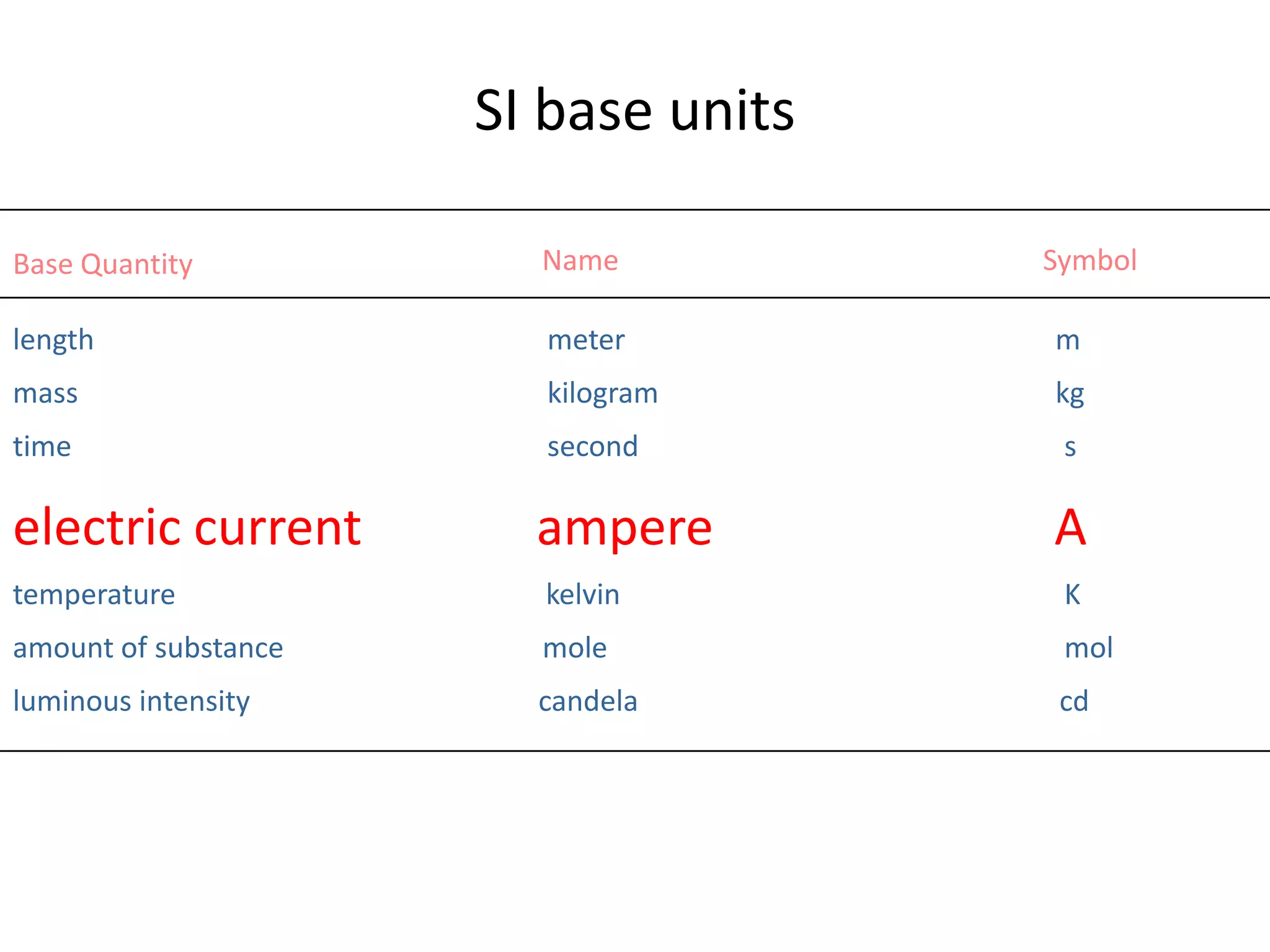
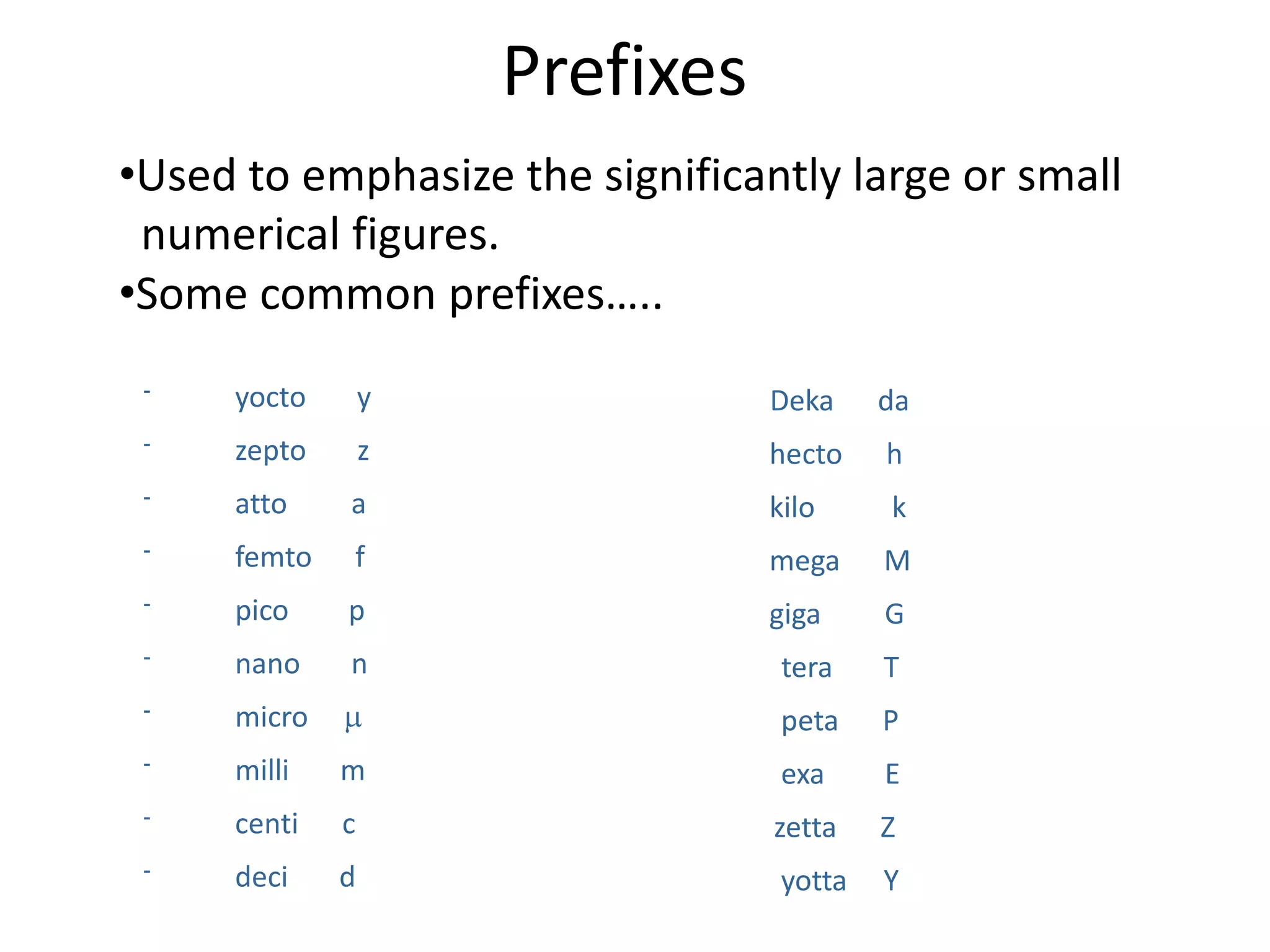
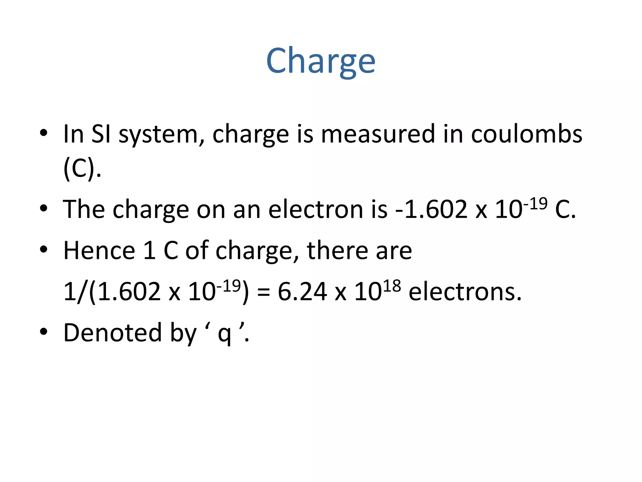
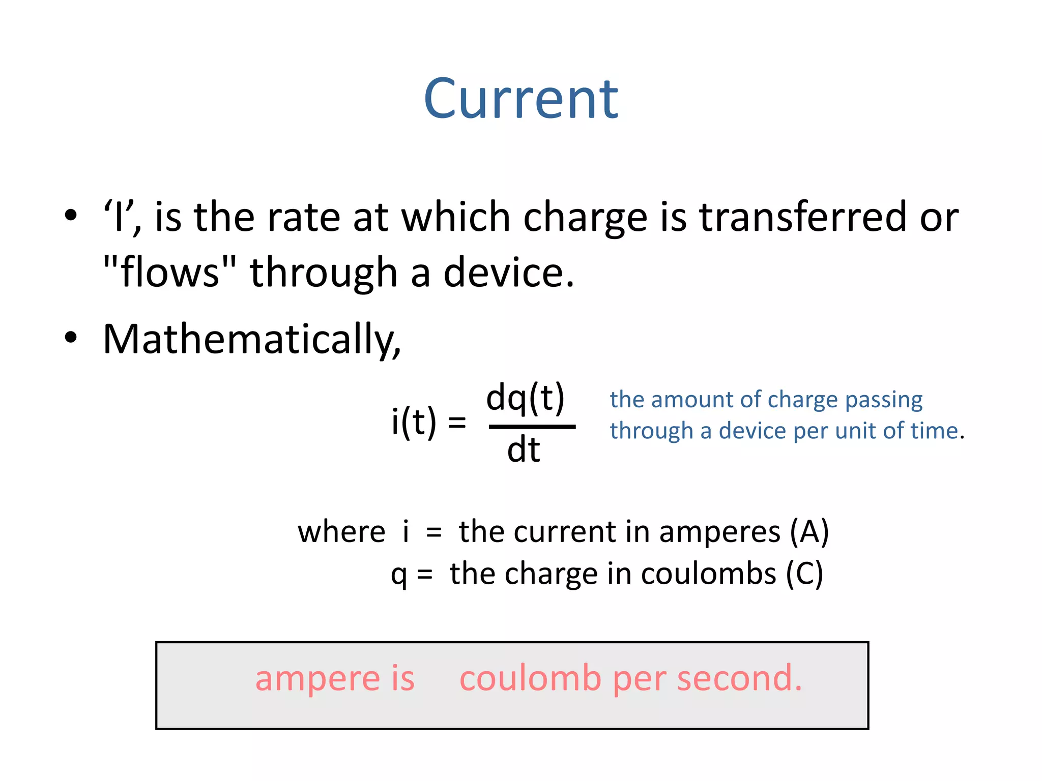
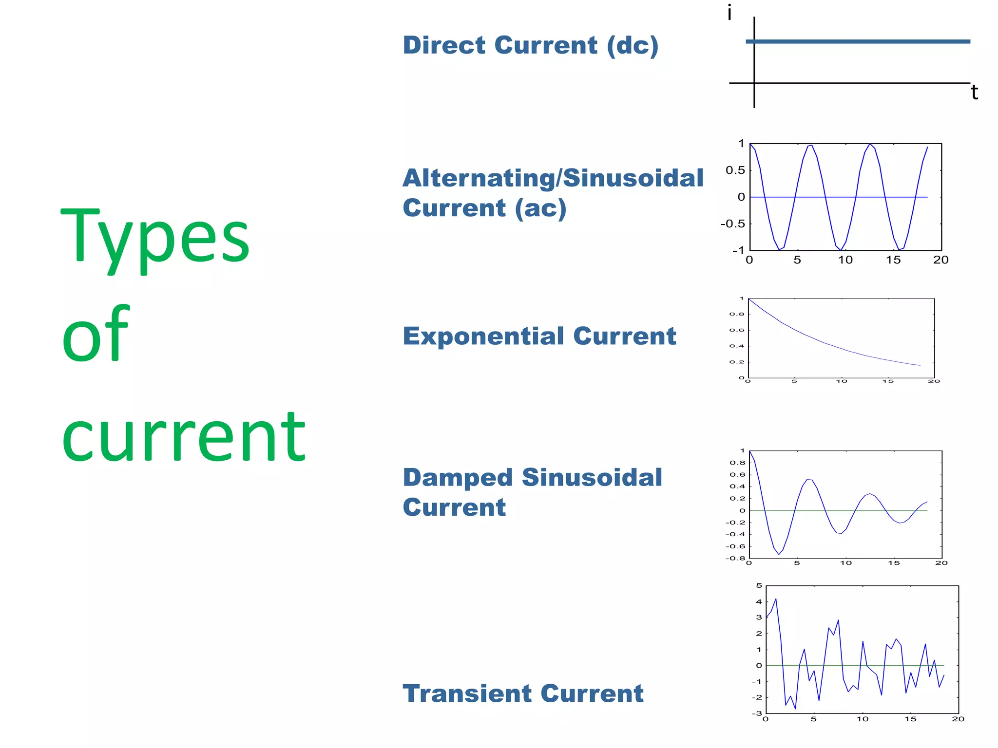
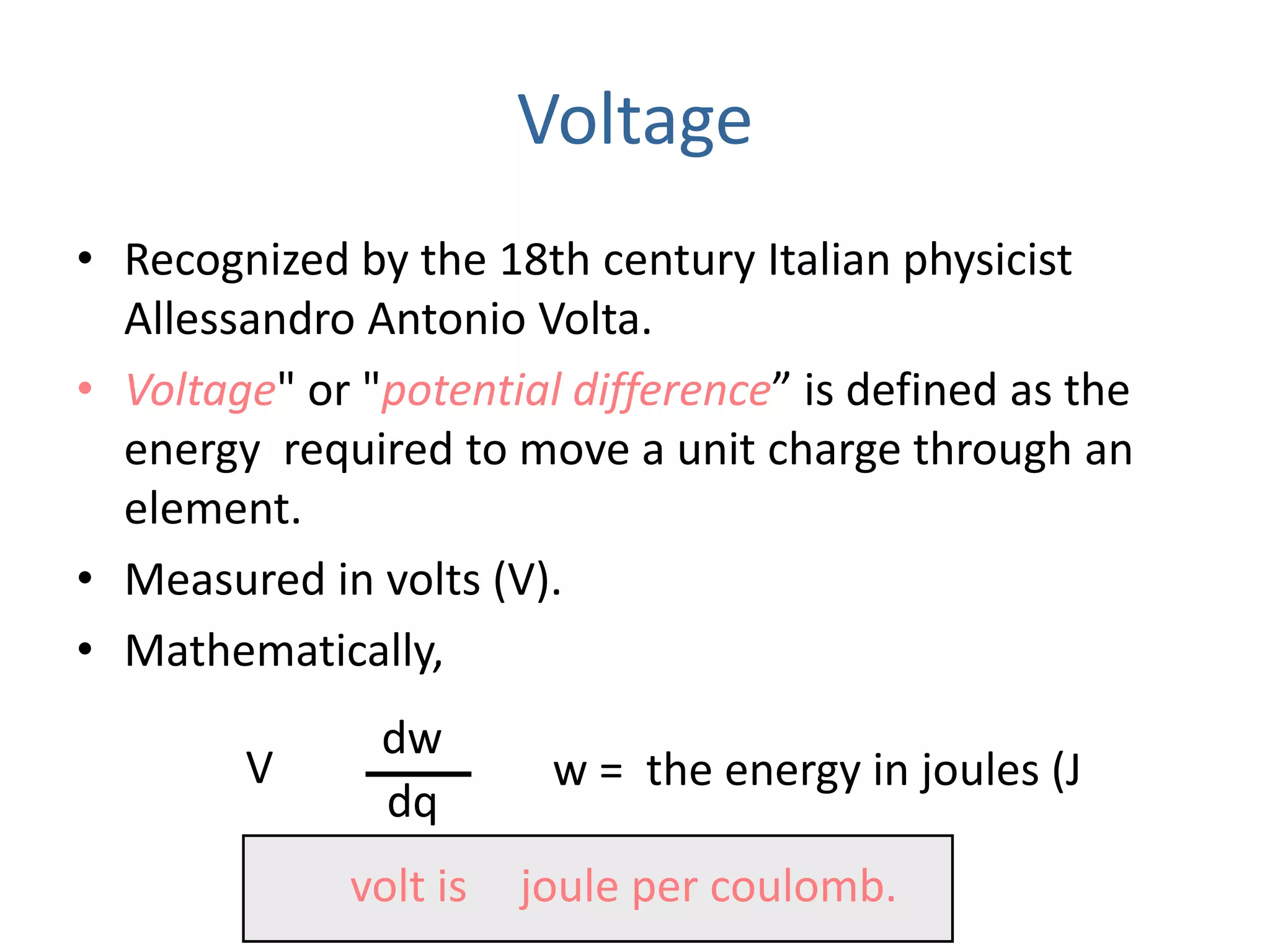
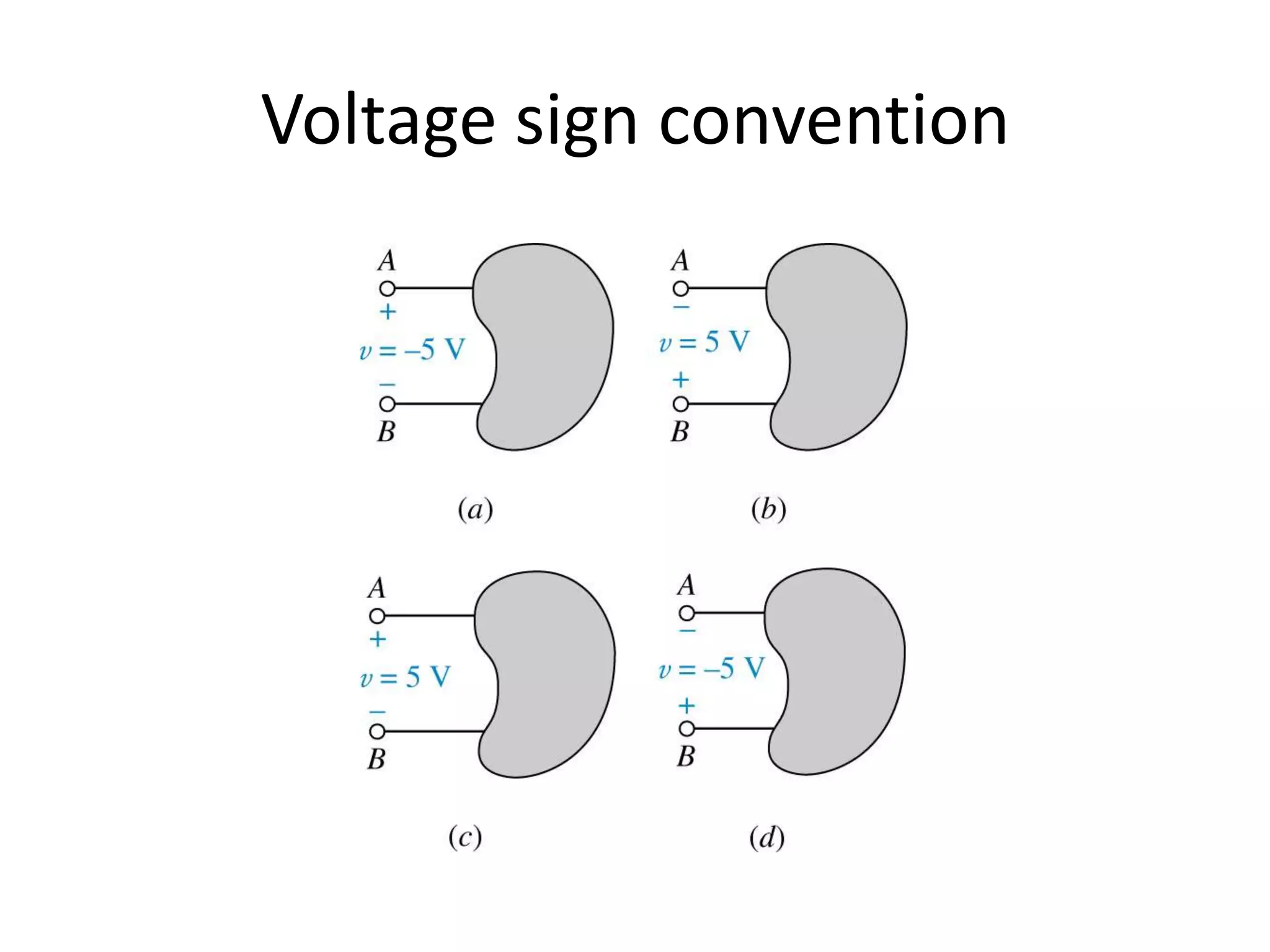
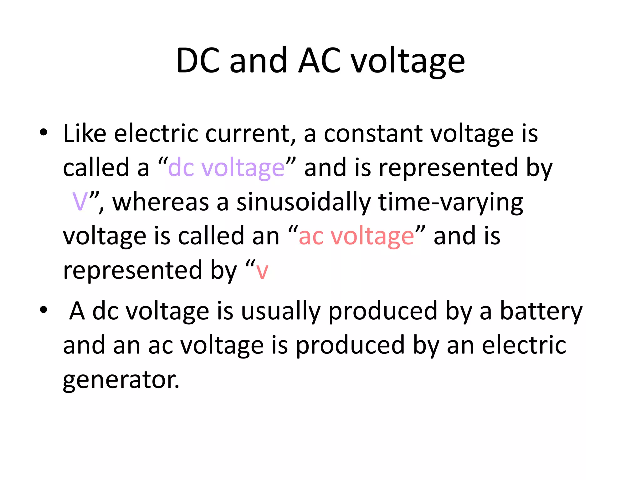
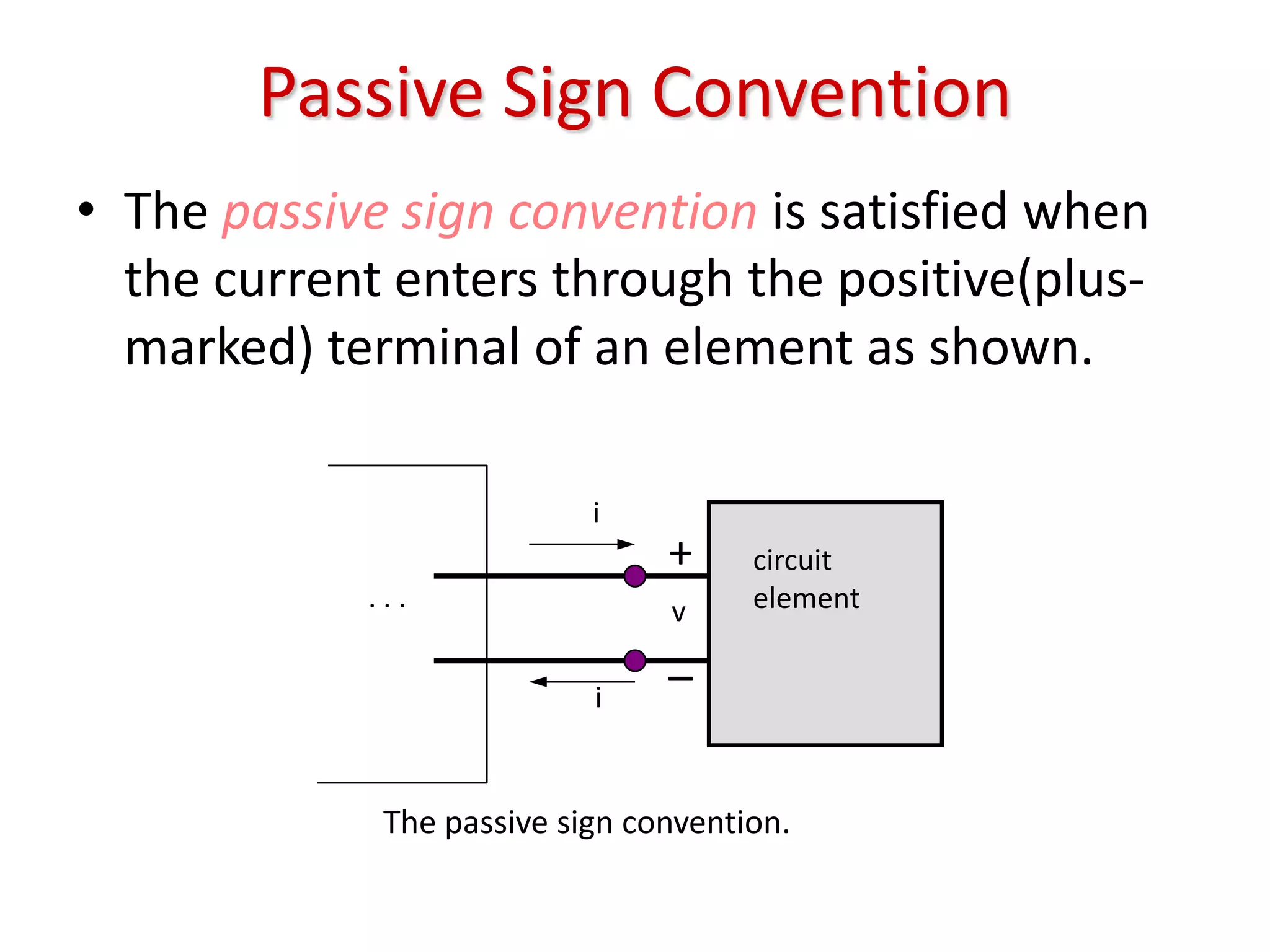
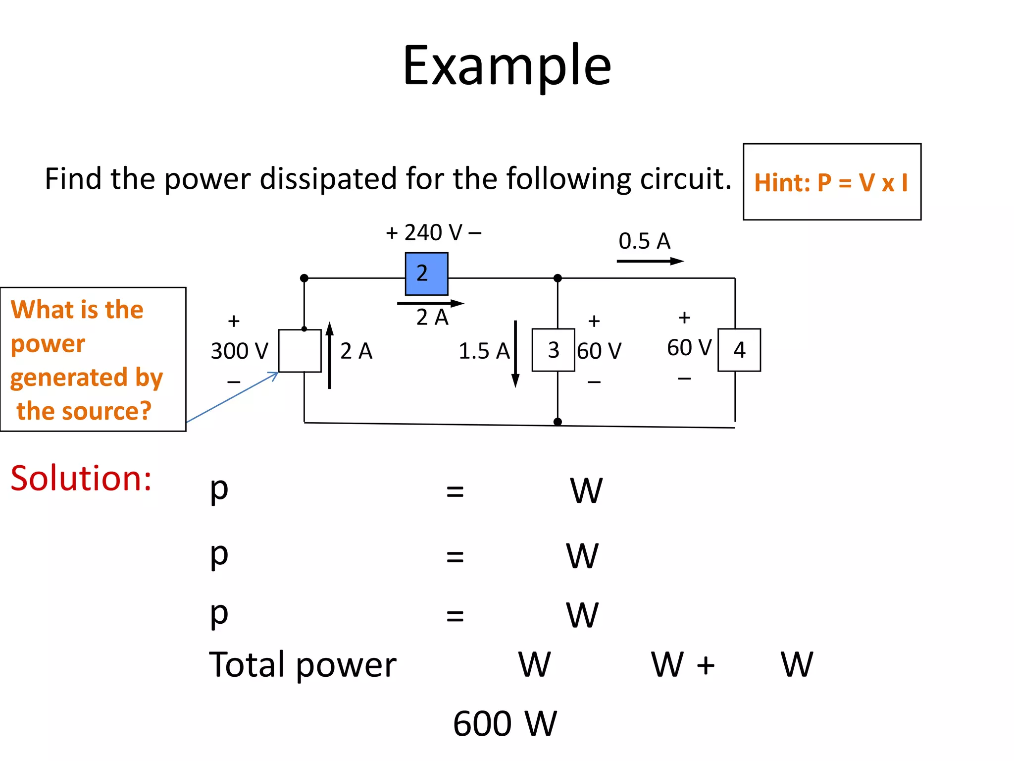
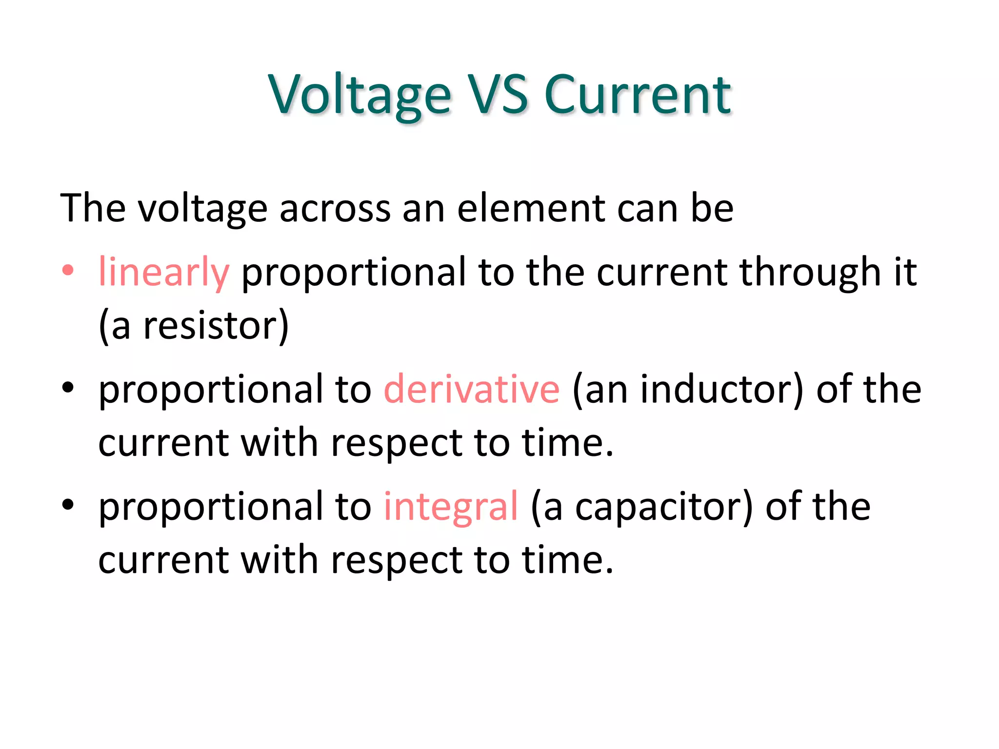
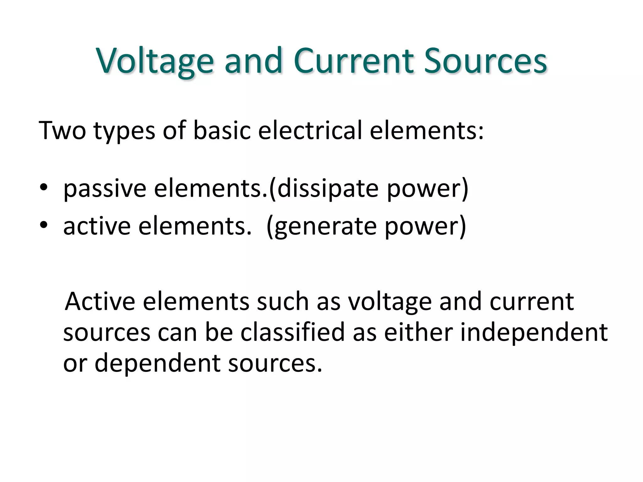
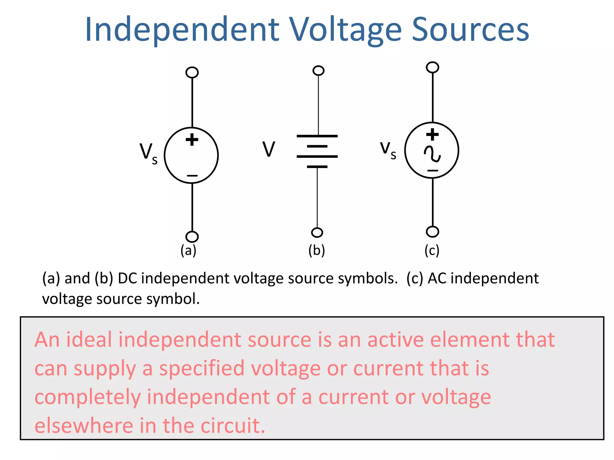
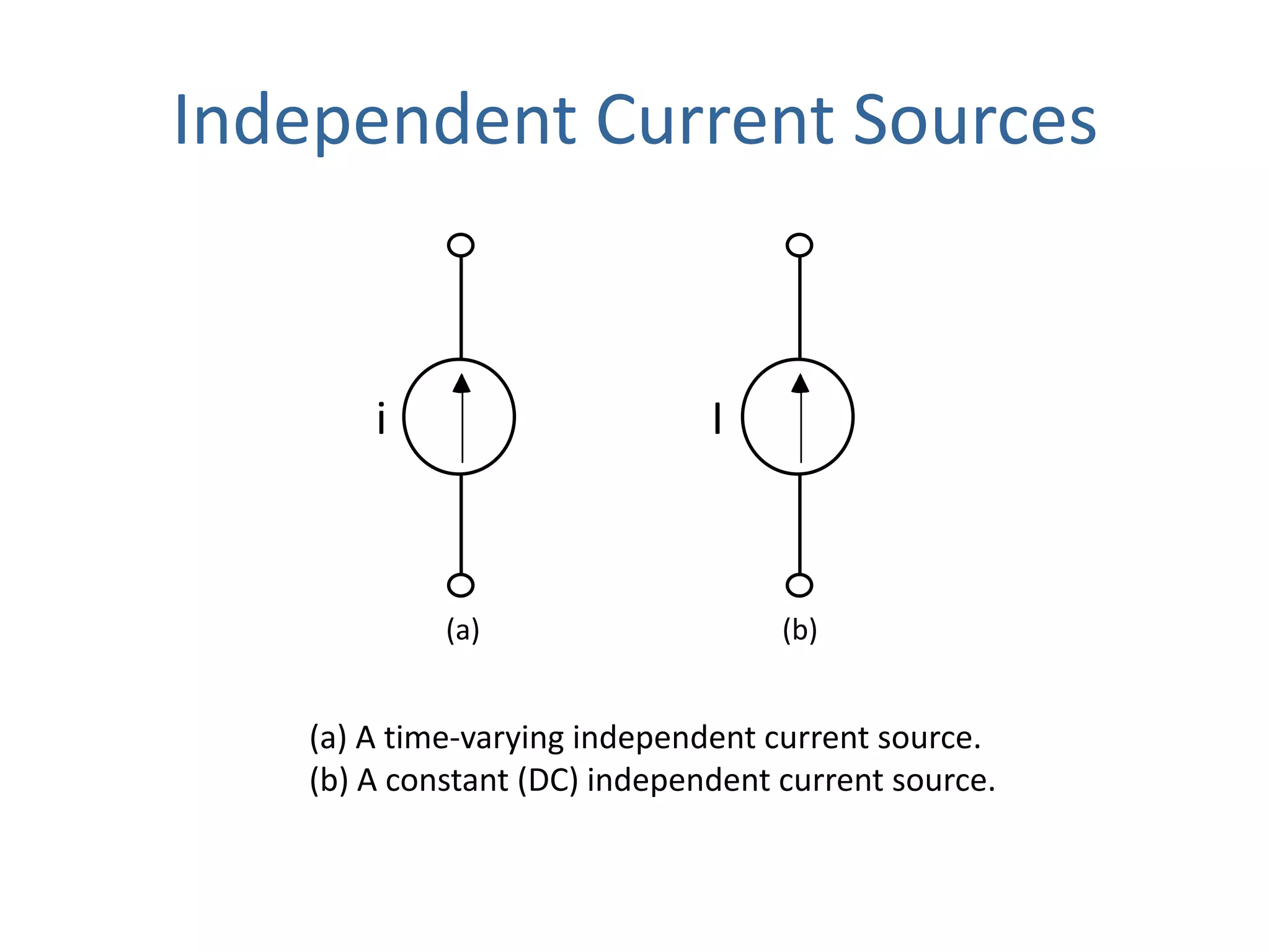
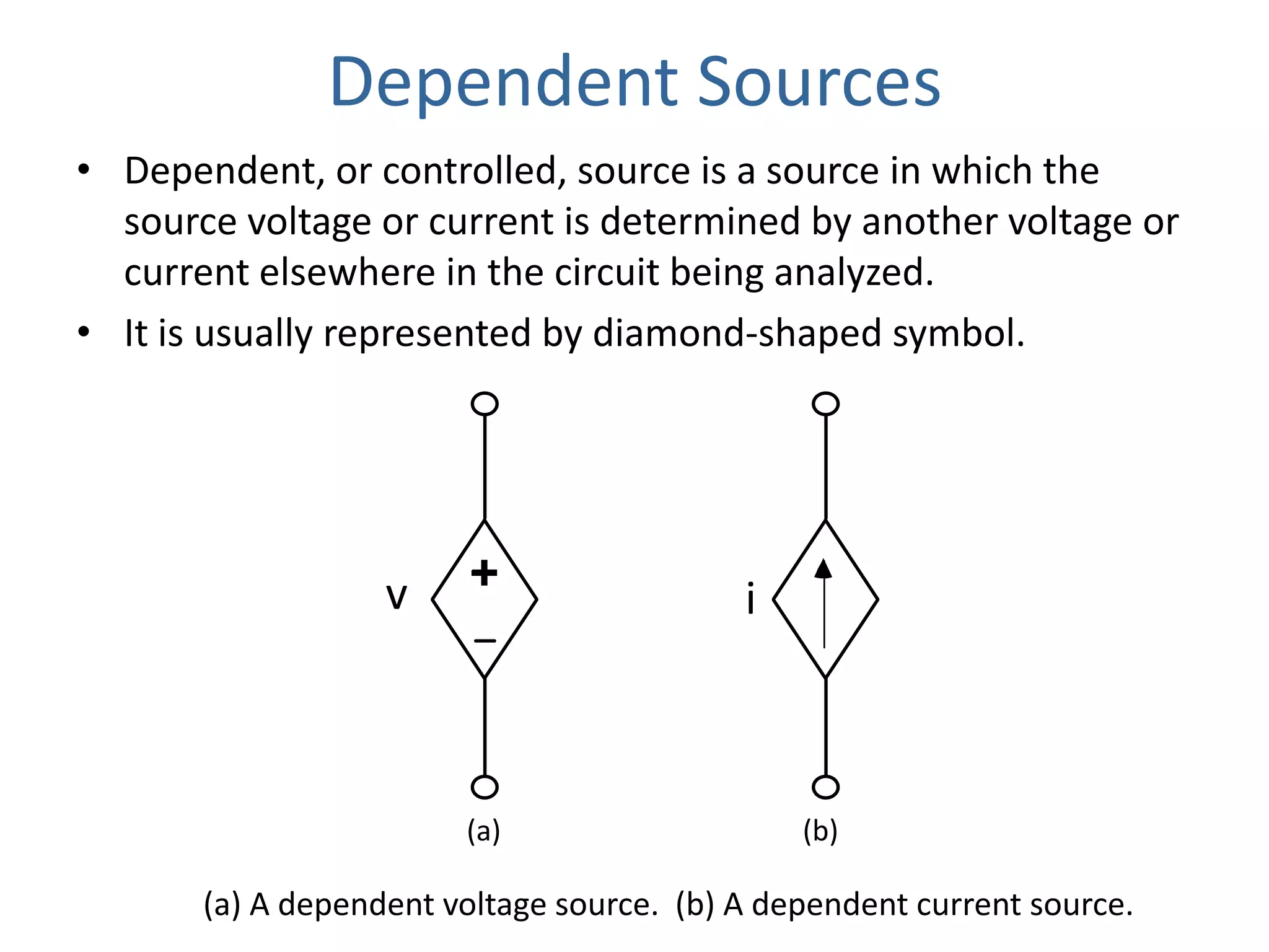
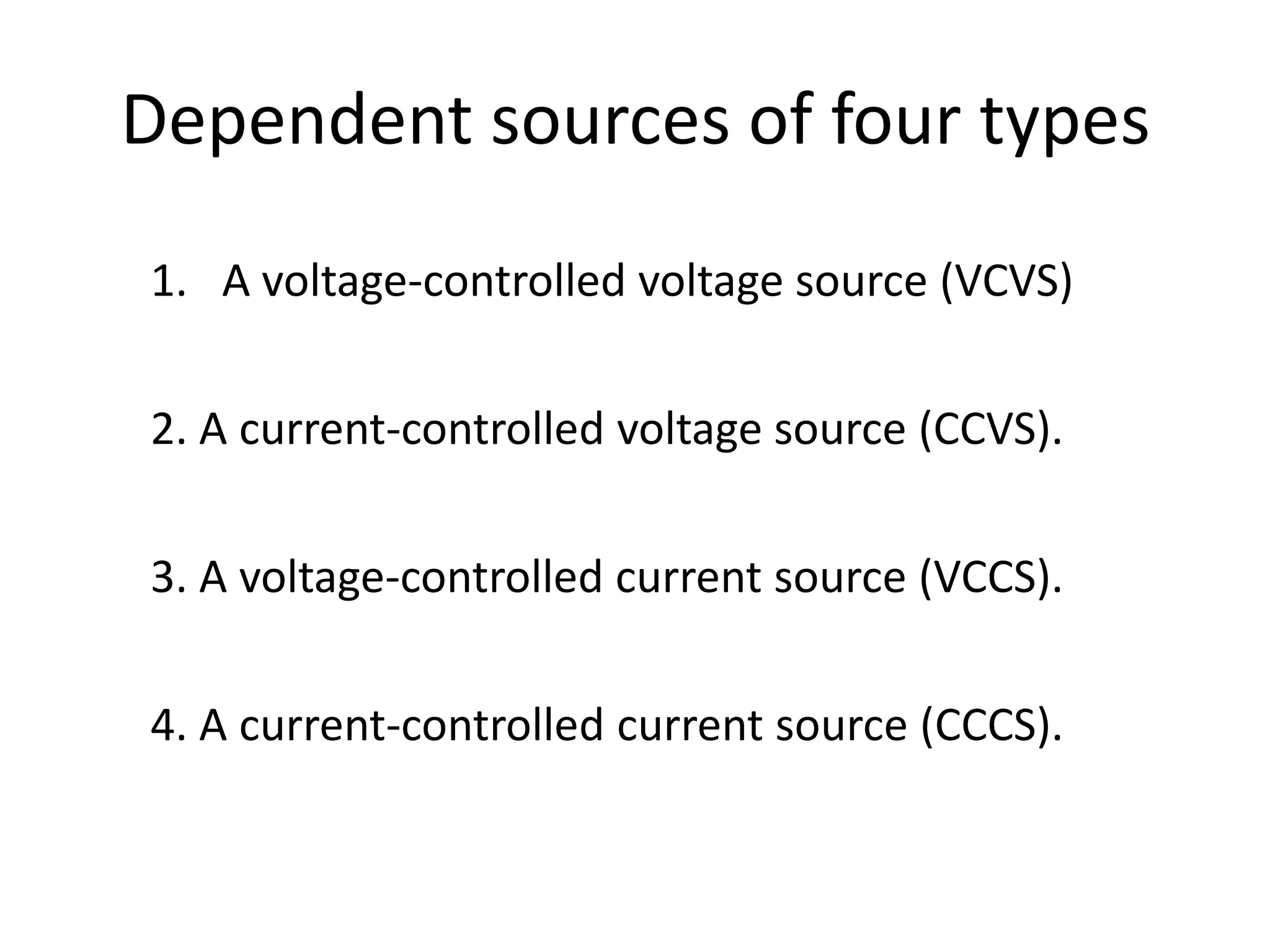
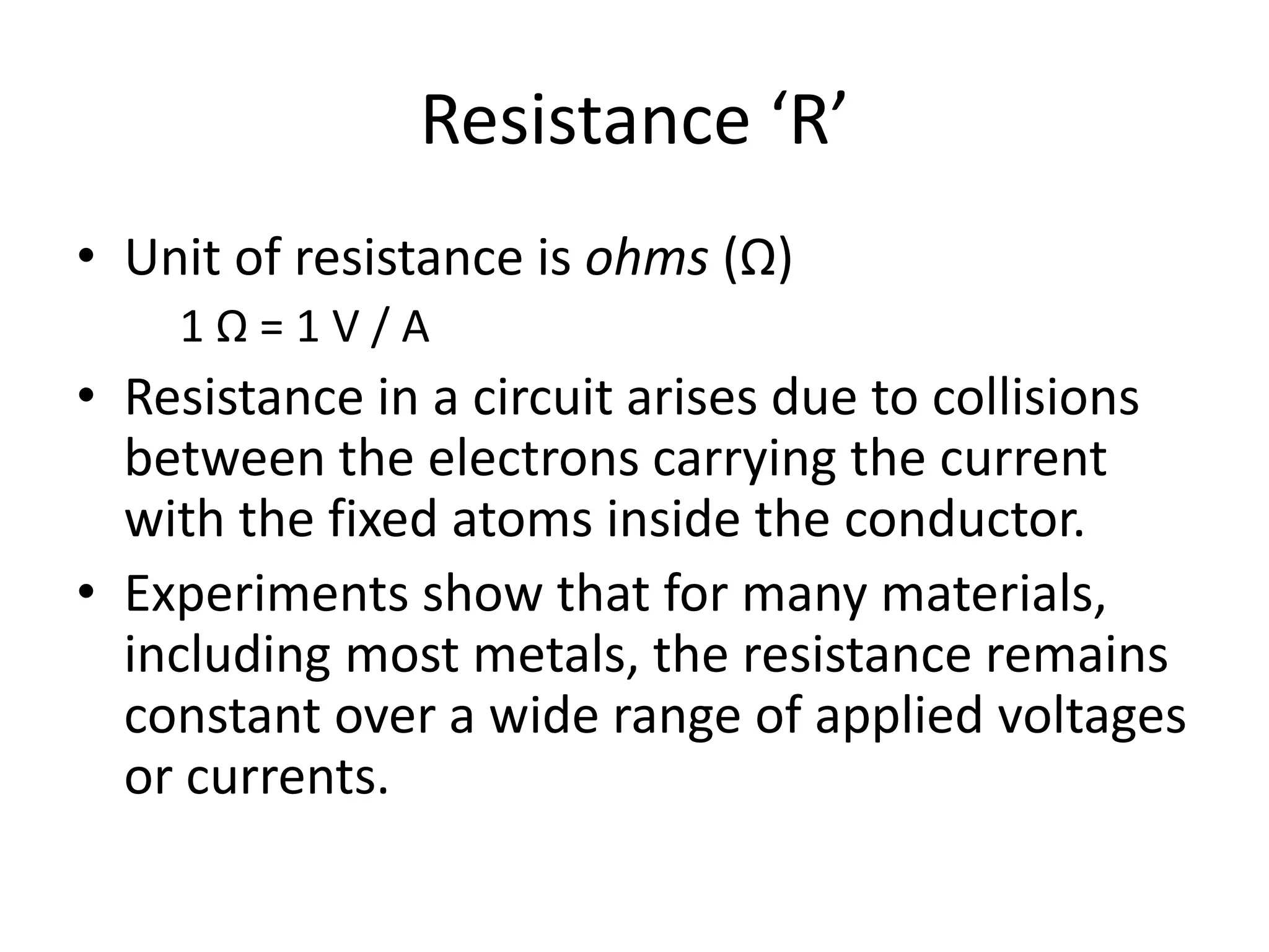
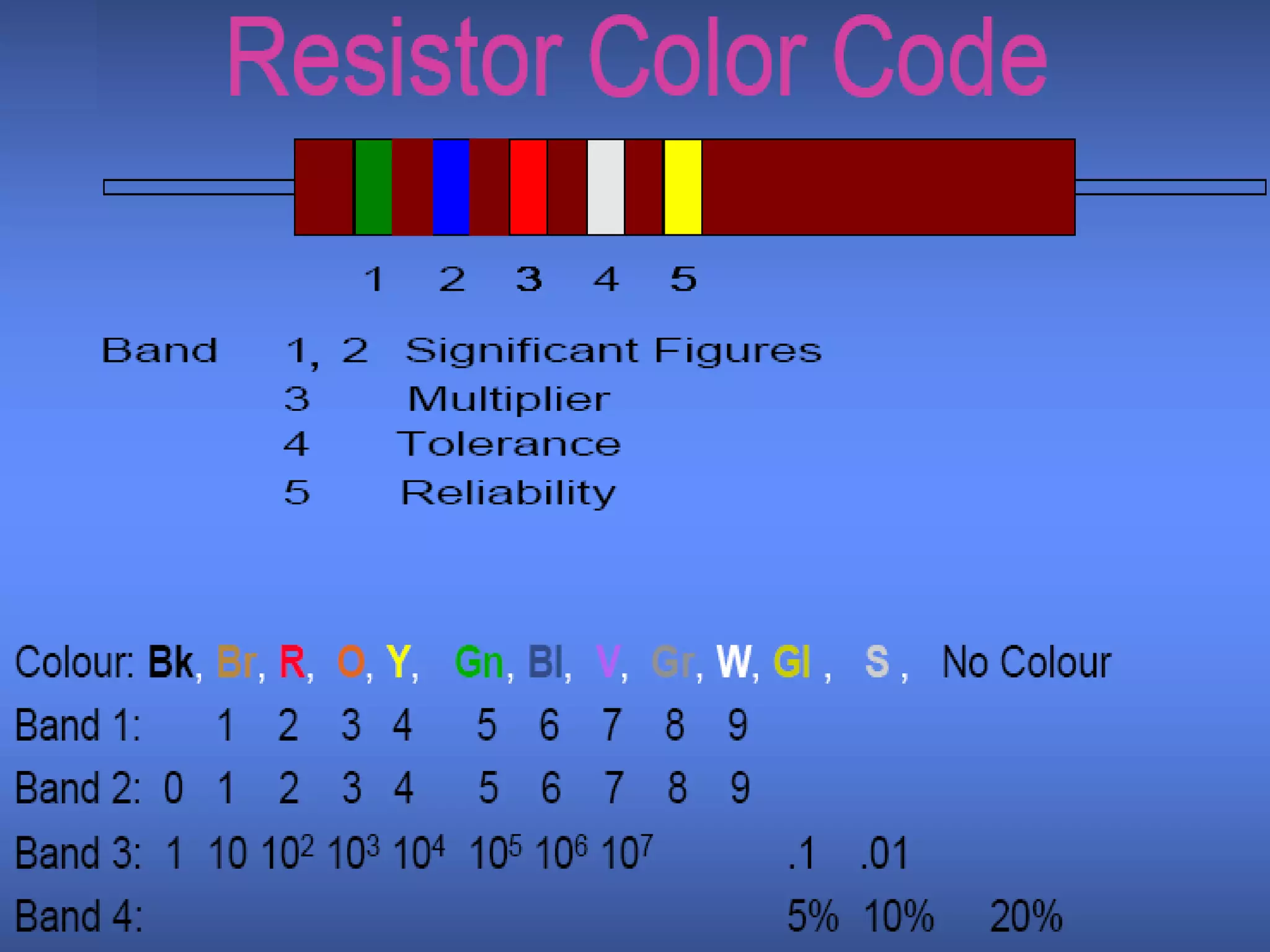
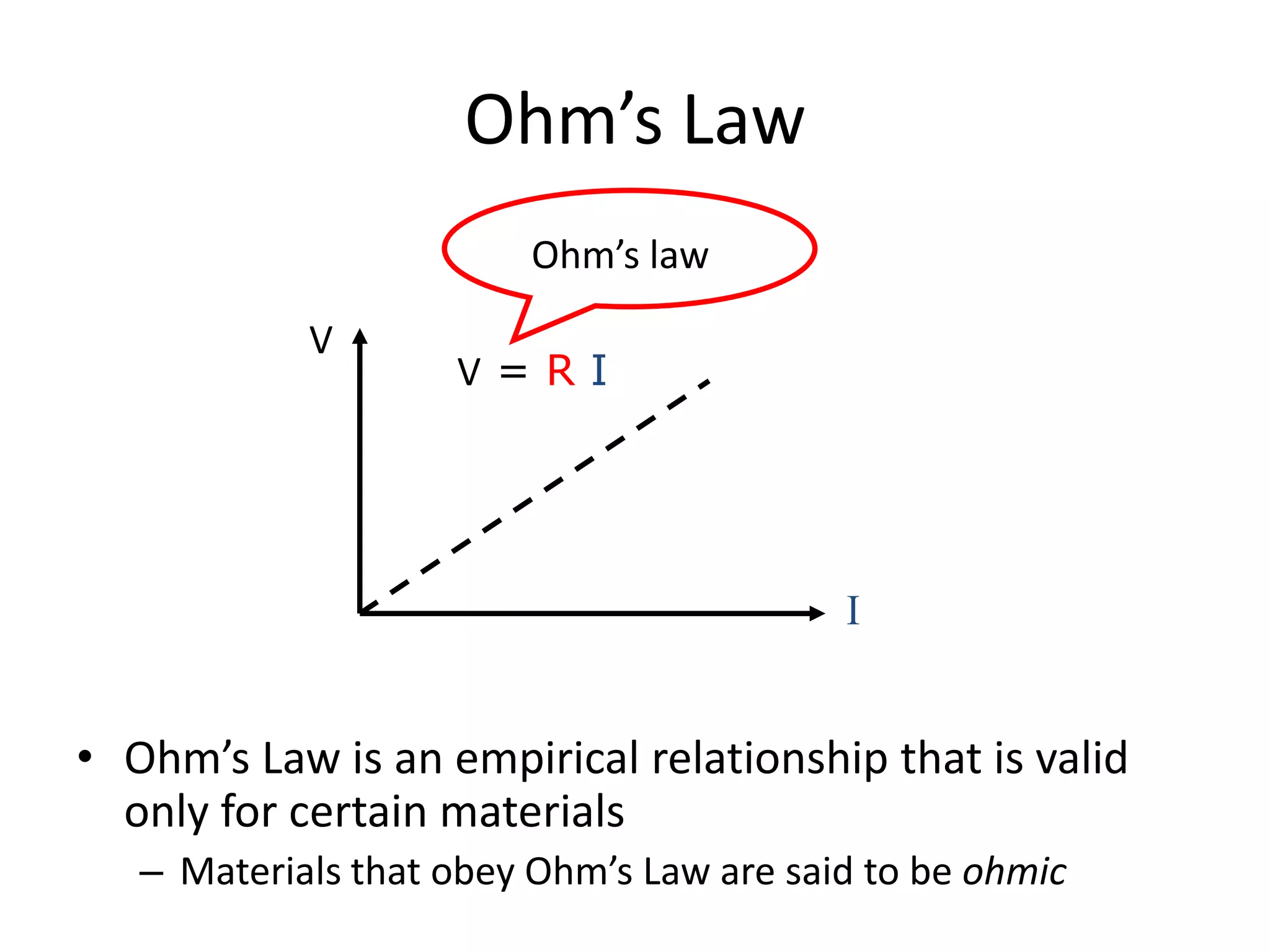
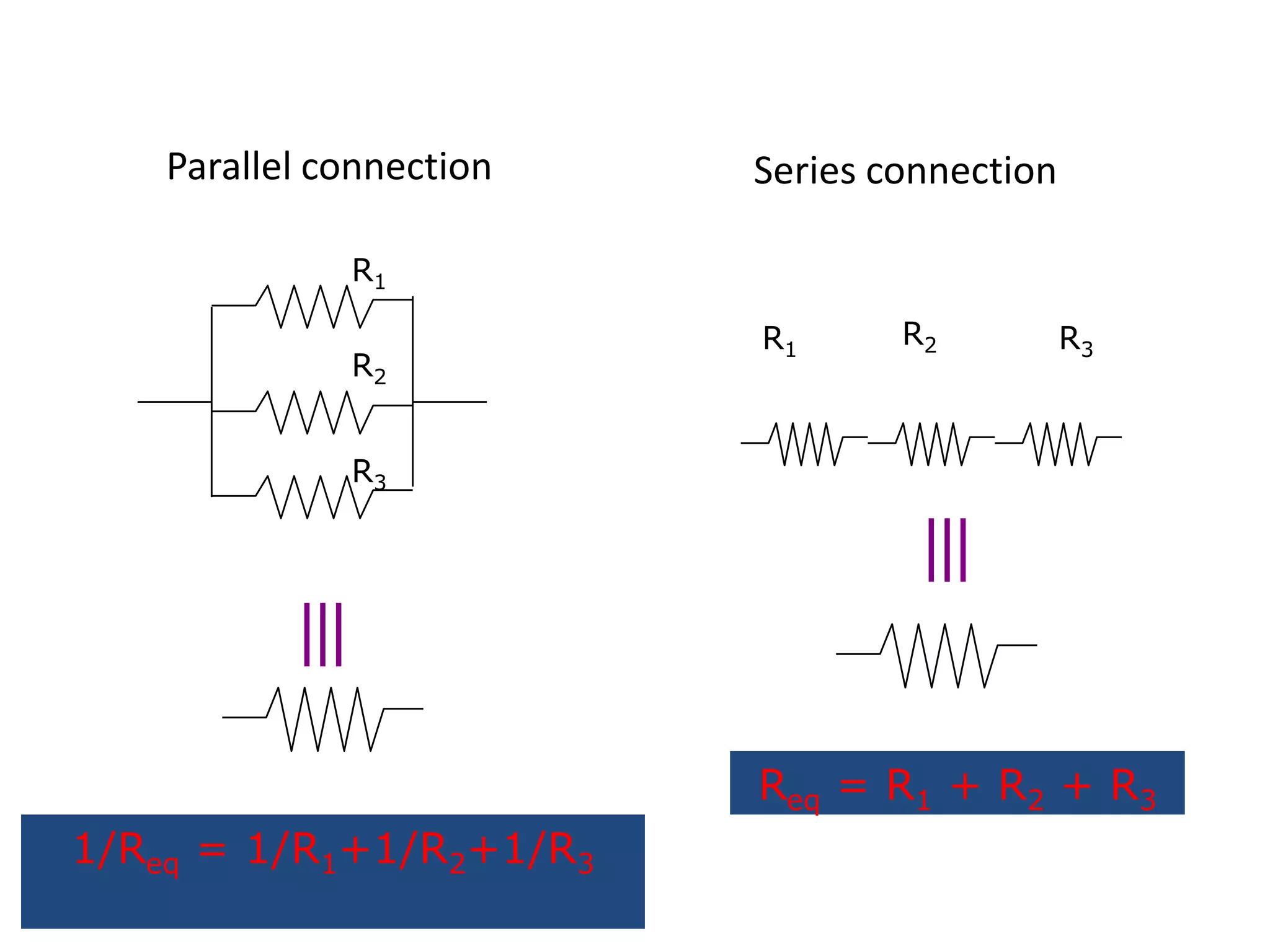
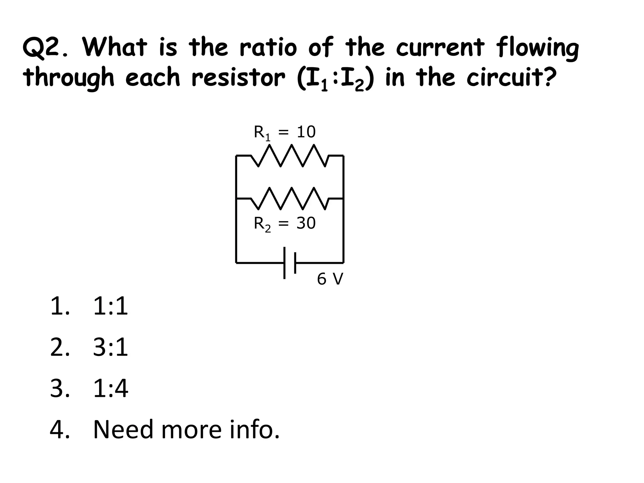

This document discusses various concepts related to electric circuits including: - Circuit elements like resistors, voltage and current sources. - Kirchhoff's laws, Ohm's law, and calculations of equivalent resistance in series and parallel circuits. - Different types of currents and voltages including direct current, alternating current, and dependent and independent sources. - Units of measurement for quantities like charge, current, voltage, resistance and power in electric circuits.


![UNIT-I Final (1)[1].pptfgcvhvjgbjhbjgbjhhvhvhvh](https://cdn.slidesharecdn.com/ss_thumbnails/unit-ifinal11-251129122433-e786871d-thumbnail.jpg?width=640&height=640&fit=bounds)