Basic electronics Tutorial 1
•
1 like•594 views

Questions on RC, LR, CR and RL circuits. 2nd Year, IIT Kharagpur

Recommended
More Related Content
What's hot
What's hot (20)
Viewers also liked
Viewers also liked (15)
Similar to Basic electronics Tutorial 1
Similar to Basic electronics Tutorial 1 (20)
More from Ankit Kumar
More from Ankit Kumar (12)
Recently uploaded
Recently uploaded (20)
Basic electronics Tutorial 1
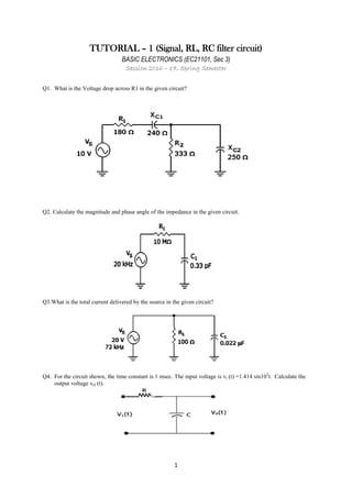
- 1. 1 TUTORIAL – 1 (Signal, RL, RC filter circuit) BASIC ELECTRONICS (EC21101, Sec 3) Session 2016 – 17, Spring Semester Q1. What is the Voltage drop across R1 in the given circuit? Q2. Calculate the magnitude and phase angle of the impedance in the given circuit. Q3.What is the total current delivered by the source in the given circuit? Q4. For the circuit shown, the time constant is 1 msec. The input voltage is vi (t) =1.414 sin103 t. Calculate the output voltage vO (t).
- 2. 2 Q5. For the circuit shown, the input voltage V (t) =U (t).Then the current i (t) is Q6. A square pulse of 3 volts amplitude is applied to the circuit shown in figure. The capacitor is initially uncharged. The output voltage vO at time t=2 sec is equal to? Q7. Find the frequency response of the circuit shown below. Which type of filter is it? Q8. The circuit shown below is driven by a sinusoidal input vi=VP cos (t/RC). Find the steady state frequency response of the circuit.
- 3. 3 Q9. In the RC circuit shown below, a square waveform is applied to the input of circuit. Draw the waveform at the output of the circuit for the conditions given below: a. If low frequency square wave is applied b. If mid frequency square wave is applied c. If high frequency square wave is applied Q10. In the circuit shown below a square waveform is applied to the input of the circuit. Draw the waveform at the output of the circuit for the conditions given below: a. If low frequency square wave is applied b. If mid frequency square wave is applied c. If high frequency square wave is applied Q11. Write the equations for v (t) for the two cases given below. Sketch the waveform v (t) for both the cases. (a): v (0) = V0 volts (b): v (0) = 0 volts Q12. Determine the type of filter for both figures (a) and (b). Also express the 3dB cut-off frequency in terms of the circuit components.
- 4. 4 Q13. Draw Thevenin equivalent circuit across the 2 ohm resistor. Use Thevenin’s theorem to find the current through the 2 ohm resistor. Q14. Define rise time of a signal. The circuit shown in figure is powered by a source which is inactive for t < 0. (a) Obtain an expression for i (t) (b) Determine the rise time for i (t) Q15. What will be the effect on the bandwidth of an RC as well as an RL network if the rise time (a) Increases (b) Decreases Q16. What is the rms value of a waveform? Determine the rms value of the following waveforms: (a) Sinusoidal waveform i (t) = Im*cos (ωt + φ) (b) Saw tooth waveform (Figure (A)) and Square waveform (Figure (B)) Q17. Two ac signals A and B have the following current amplitude ratios in the dB scale a) 3 dB, b) 20 dB. Find these ratios in the absolute scale. Q18. Two ac signals A and B have the following power ratios in the dB scale a) 6 dB, b) -10 db. Find these ratios in the absolute scale. Q19. Draw a positive going negative pulse waveform and a positive impulse waveform. Q20. A 5V battery is connected at t = 0 sec. to an oscilloscope. Consider oscilloscope to be an RC circuit with R = 1 MΩ and C = 1 pF. Find the time the oscilloscope will take to show the voltage to rise to 4.5 V. Also calculate the rise time of the oscilloscope. Q21. Calculate the approximate peak value of the waveform shown in an oscilloscope when a 6.77 KHz, 5V sinusoidal signal is applied to the oscilloscope. Consider the oscilloscope to be an RC circuit. Recalculate the same if the applied signal frequency is changed to 3.385 MHz.