Downloaded 190 times


![ Using these formulas, we can calculate the time delay
for the previous example:
TO = 7 T-States
(Delay of the MVI instruction)
TL = (14 X 255) - 3 = 3567 T-States
(14 T-States for the 2 instructions repeated 255 times
(FF16 = 25510) reduced by the 3 T-States for the final JNZ.)
Tdelay = [(TO + TL )/f]
= (7 + 3567)/2MHz
= (3574) X 0.5 mSec
= 1.787 mSec
(Assuming f = 2 MHz)
Using One Register](https://image.slidesharecdn.com/counterstimedelay-180720192310/85/Counters-amp-time-delay-10-320.jpg)
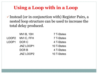

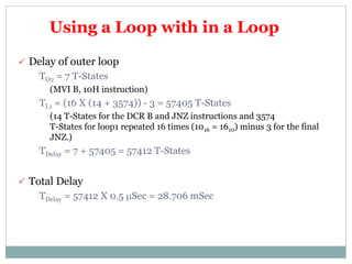
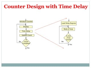


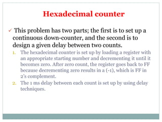


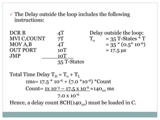
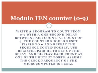

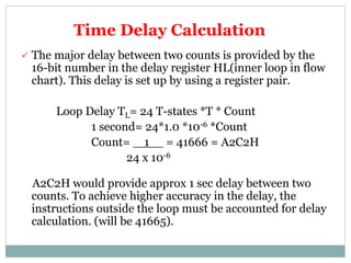


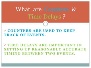
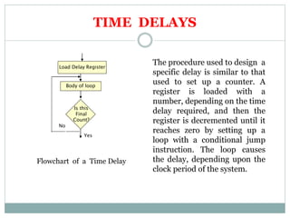
The document discusses counters and time delays in microprocessors. It defines counters as circuits used to keep track of events and time delays as important for setting timing between events. It then provides details on designing counters and time delays using registers, loops, and instructions. It discusses different techniques for creating longer time delays using register pairs, nested loops, and inserting dummy instructions. Example programs are given to count hexadecimal numbers and generate pulse waveforms with delays. Common errors in programming counters and delays are also outlined.