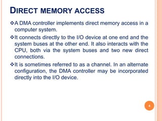
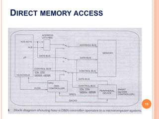
DMA (DIRECT MEMORY ACCESS)
DIRECT MEMORY ACCESS
 An important aspect governing the Computer System
performance is the transfer of data between memory
and I/O devices.
 The operation involves loading programs or data files
from disk into memory, saving file on disk, and
accessing virtual memory pages on any secondary
storage medium.
 Consider a typical system consisting of a CPU,
memory and one or more input/output devices.
Assume one of the I/O devices is a disk drive and that
the computer must load a program from this drive into
memory.
2
The CPU would read the first byte of the program and
then write that byte to memory. Then it would do the
same for the second byte, until it had loaded the entire
program into memory.
This process proves to be inefficient. Loading data into,
and then writing data out of the CPU significantly slows
down the transfer. The CPU does not modify the data
at all, so it only serves as an additional stop for data on
the way to it’s final destination.
The process would be much quicker if we could bypass
the CPU & transfer data directly from the I/O device to
memory.
Direct Memory Access does exactly that.
DIRECT MEMORY ACCESS
3
A DMA controller implements direct memory access in a
computer system.
It connects directly to the I/O device at one end and the
system buses at the other end. It also interacts with the
CPU, both via the system buses and two new direct
connections.
It is sometimes referred to as a channel. In an alternate
configuration, the DMA controller may be incorporated
directly into the I/O device.
DIRECT MEMORY ACCESS
4
 Direct memory access (DMA) is a process in which an
external device takes over the control of system bus from
the CPU.
 DMA is for high-speed data transfer from/to mass
storage peripherals, e.g. hard disk drive, magnetic tape,
CD-ROM, and sometimes video controllers.
The basic idea of DMA is to transfer blocks of data directly
between memory and peripherals. The data don’t go
through the microprocessor but the data bus is occupied
“Normal” transfer of one data byte takes up to 29 clock
cycles. The DMA transfer requires only 5 clock cycles.
Nowadays, DMA can transfer data as fast as 60 M byte per
second. The transfer rate is limited by the speed of memory
and peripheral devices.
DIRECT MEMORY ACCESS
5
In a word the DMA controller temporarily borrows the
data bus, address bus and control bus from the
microprocessor and transfers the data bytes directly
from the disk to a series of memory locations.
The data transfer is handled totally in hardware.
It is much faster than it would be if done by program
instructions.
A DMA controller can also transfer data from memory to
a port.
DIRECT MEMORY ACCESS
6
PIN DIAGRAM
7
8
9
8237 INTERNAL REGISTERS
CAR
 The current address register holds a 16-bit
memory address used for the DMA transfer.
 Each channel has its own current address
register for this purpose.
 When a byte of data is transferred during a DMA
operation, CAR is either incremented or
is
decremented depending on how it
programmed.
10
CWCR
 The current word count register programs a
channel for the number of bytes to transfer during a
DMA operation. The number loaded into this register is
one less than the number of bytes transferred. For
example, if 10 is loaded into the CWCR, then 11 bytes
are transferred during DMA action.
11
CR
 The command register programs the operation of
the 8237 DMA controller.
 The register uses bit position 0 to select the
memory-to-memory DMA transfer mode.
 Memory-to-memory DMA transfers use DMA
channel 0 to hold the source address.
 DMA channel 1 holds the destination address.
12
command register.
13
 The status register shows
status of each DMA
channel. The TC bits
indicate if the channel has
reached its terminal count
(transferred all its bytes).
 When the terminal count is
reached, the DMA transfer
is terminated.
 The request bits indicate
whether the DREQ input is
given.
SR
14
DIRECT MEMORY ACCESS
15
When the system is first turned on, the switches are in
the up position, so the buses are connected from the
microprocessor to system memory and peripherals.
To read a disk file a series of commands is sent to the
smart disk controller device, telling it to find and read
the desired block of data from the disk.
When the disk controller has the first byte of data from
the disk block ready, it sends a DMA request, DREQ,
signal to the DMA controller.
If that input of the DMA controller is unmasked, the
DMA controller will send a hold-request, HRQ, signal
to the microprocessor HOLD input.
DIRECT MEMORY ACCESS
16
The microprocessor will respond to this input by
floating its buses and sending out a hold-acknowledge
signal, HLDA. To the DMA controller.
When the DMA controller receives the HLDA signal it
will send, it will send out a control signal which throws
the three bus switches down to their DMA position.
This disconnects the processor from the buses and
connects the DMA controller to the buses.
When the DMA controller gets control of the buses, it
sends out the memory address where the first byte of
data from the disk controller is to be written.
DIRECT MEMORY ACCESS
17
Next the DMA controller sends a DMA-acknowledge,
DACKO, signal to the disk controller device to tell it to
get ready to output the byte.
Finally the DMA controller asserts both the MEMW and
the IOR lines on the control bus.
The byte of data then is transferred directly from the
disk controller to the memory location without passing
through the CPU or the DMA controller.
When the data transfer is complete, the DMA controller
unasserts its hold-request signal to the processor and
releases the buses.
DIRECT MEMORY ACCESS
18
A DMA transfer from memory to the disk controller
proceeds in a similar manner except that the DMA
controller asserts the memory-read control signal,
MEMR and the output-write control signal, IOW.
DIRECT MEMORY ACCESS
19
DMA TRANSFER TIMING DIAGRAM
 See the details from Book (D.V. Hall)
20
Thank You
21

Direct memory access controller slide.pptx

  • 1.
  • 2.
    DIRECT MEMORY ACCESS An important aspect governing the Computer System performance is the transfer of data between memory and I/O devices.  The operation involves loading programs or data files from disk into memory, saving file on disk, and accessing virtual memory pages on any secondary storage medium.  Consider a typical system consisting of a CPU, memory and one or more input/output devices. Assume one of the I/O devices is a disk drive and that the computer must load a program from this drive into memory. 2
  • 3.
    The CPU wouldread the first byte of the program and then write that byte to memory. Then it would do the same for the second byte, until it had loaded the entire program into memory. This process proves to be inefficient. Loading data into, and then writing data out of the CPU significantly slows down the transfer. The CPU does not modify the data at all, so it only serves as an additional stop for data on the way to it’s final destination. The process would be much quicker if we could bypass the CPU & transfer data directly from the I/O device to memory. Direct Memory Access does exactly that. DIRECT MEMORY ACCESS 3
  • 4.
    A DMA controllerimplements direct memory access in a computer system. It connects directly to the I/O device at one end and the system buses at the other end. It also interacts with the CPU, both via the system buses and two new direct connections. It is sometimes referred to as a channel. In an alternate configuration, the DMA controller may be incorporated directly into the I/O device. DIRECT MEMORY ACCESS 4
  • 5.
     Direct memoryaccess (DMA) is a process in which an external device takes over the control of system bus from the CPU.  DMA is for high-speed data transfer from/to mass storage peripherals, e.g. hard disk drive, magnetic tape, CD-ROM, and sometimes video controllers. The basic idea of DMA is to transfer blocks of data directly between memory and peripherals. The data don’t go through the microprocessor but the data bus is occupied “Normal” transfer of one data byte takes up to 29 clock cycles. The DMA transfer requires only 5 clock cycles. Nowadays, DMA can transfer data as fast as 60 M byte per second. The transfer rate is limited by the speed of memory and peripheral devices. DIRECT MEMORY ACCESS 5
  • 6.
    In a wordthe DMA controller temporarily borrows the data bus, address bus and control bus from the microprocessor and transfers the data bytes directly from the disk to a series of memory locations. The data transfer is handled totally in hardware. It is much faster than it would be if done by program instructions. A DMA controller can also transfer data from memory to a port. DIRECT MEMORY ACCESS 6
  • 7.
  • 8.
  • 9.
  • 10.
    8237 INTERNAL REGISTERS CAR The current address register holds a 16-bit memory address used for the DMA transfer.  Each channel has its own current address register for this purpose.  When a byte of data is transferred during a DMA operation, CAR is either incremented or is decremented depending on how it programmed. 10
  • 11.
    CWCR  The currentword count register programs a channel for the number of bytes to transfer during a DMA operation. The number loaded into this register is one less than the number of bytes transferred. For example, if 10 is loaded into the CWCR, then 11 bytes are transferred during DMA action. 11
  • 12.
    CR  The commandregister programs the operation of the 8237 DMA controller.  The register uses bit position 0 to select the memory-to-memory DMA transfer mode.  Memory-to-memory DMA transfers use DMA channel 0 to hold the source address.  DMA channel 1 holds the destination address. 12
  • 13.
  • 14.
     The statusregister shows status of each DMA channel. The TC bits indicate if the channel has reached its terminal count (transferred all its bytes).  When the terminal count is reached, the DMA transfer is terminated.  The request bits indicate whether the DREQ input is given. SR 14
  • 15.
  • 16.
    When the systemis first turned on, the switches are in the up position, so the buses are connected from the microprocessor to system memory and peripherals. To read a disk file a series of commands is sent to the smart disk controller device, telling it to find and read the desired block of data from the disk. When the disk controller has the first byte of data from the disk block ready, it sends a DMA request, DREQ, signal to the DMA controller. If that input of the DMA controller is unmasked, the DMA controller will send a hold-request, HRQ, signal to the microprocessor HOLD input. DIRECT MEMORY ACCESS 16
  • 17.
    The microprocessor willrespond to this input by floating its buses and sending out a hold-acknowledge signal, HLDA. To the DMA controller. When the DMA controller receives the HLDA signal it will send, it will send out a control signal which throws the three bus switches down to their DMA position. This disconnects the processor from the buses and connects the DMA controller to the buses. When the DMA controller gets control of the buses, it sends out the memory address where the first byte of data from the disk controller is to be written. DIRECT MEMORY ACCESS 17
  • 18.
    Next the DMAcontroller sends a DMA-acknowledge, DACKO, signal to the disk controller device to tell it to get ready to output the byte. Finally the DMA controller asserts both the MEMW and the IOR lines on the control bus. The byte of data then is transferred directly from the disk controller to the memory location without passing through the CPU or the DMA controller. When the data transfer is complete, the DMA controller unasserts its hold-request signal to the processor and releases the buses. DIRECT MEMORY ACCESS 18
  • 19.
    A DMA transferfrom memory to the disk controller proceeds in a similar manner except that the DMA controller asserts the memory-read control signal, MEMR and the output-write control signal, IOW. DIRECT MEMORY ACCESS 19
  • 20.
    DMA TRANSFER TIMINGDIAGRAM  See the details from Book (D.V. Hall) 20
  • 21.