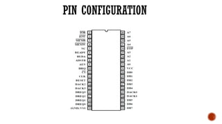
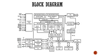
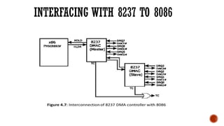
8237 DMA CONTROLLER
Presented By
Revanth Kumar T R
INTRODUCTION
 Direct Memory Access (DMA) is a method of allowing data to be moved from
one location to another in a computer without intervention from the central
processor (CPU).
  It is also a fast way of transferring data within (and sometimes between)
computer.
  The DMA I/O technique provides direct access to the memory while the
microprocessor is temporarily disabled.
  The DMA controller temporarily borrows the address bus, data bus and
control bus from the microprocessor and transfers the data directly from the
external devices to a series of memory locations (and vice versa).
BASIC DMA OPERATION
we control signals are used to request and acknowledge a direct memory
access (DMA) transfer in the microprocessor-based system.
  The HOLD signal as an input(to the processor) is used to request a DMA
action.
  The HLDA signal as an output that acknowledges the DMA action.
 When the processor recognizes the hold, it stops its execution and enters
hold cycles.
4. Cont., HOLD input has higher priority than INTR or NMI

 The only microprocessor pin that has a higher priority than a HOLD is the
RESET pin.
 HLDA becomes active to indicate that the processor has placed its buses
at high- impedance state.
FEATURES
• It provides various modes of DMA.
• It provides on chip 4 independent channel. The no of channel can be increased by
cascading.
• Each channel can be used in auto initialize mode.
• It can transfer data from memory to memory.
• In memory to memory transfer single word can be written in all location of memory
block.
• Address of memory is ether increment or decrement .
• Clock frequency 3Mhz.
• Data transfer rate 1.6 Mbps/sec
PIN CONFIGURATION
 Vcc : +5v supply
 GND : ground
 Clk input : Clock Input controls the internal operations of the 8237A and its rate of data transfers.
The input may be driven at up to 5 MHz for the 8237A-5.
 Cs input :Chip Select is an active low input used to select the 8237A as an I/O device during the
Idle cycle.This allows CPU communication on the data bus.
 Reset : Reset is an active high input which clears the Command, Status, Request and Temporary
registers.
 Ready : Ready is an input used to extend the memory read and write pulses from the 8237A to
accommodate slow memories or I/O peripheral devices
 HLDA:HOLD ACKNOWLEDGE:The active high Hold Acknowledge from the CPU indicates that it
has relinquished control of the system busses.
 DREQ0 ±DREQ3: The DMA Request lines are individual asynchronous channel request inputs used
by peripheral circuits to obtain DMA service. In fixed Priority, DREQ0 has the highest priority and
DREQ3 has the lowest priority. A request is generated by activating the DREQ line of a channel.
 DB0 ±DB7:
 DATA BUS:The Data Bus lines are bidirectional three-state signals connected to the system
data bus.The outputs are enabled in the Program condition during the I/O Read to output
the contents of an Address register, a Status register, the Temporary register or a Word
Count register to the CPU.The outputs are disabled and the inputs are read during an I/O
Write cycle when the CPU is programming the 8237A control registers. During DMA cycles
the most significant 8 bits of the address are output onto the data bus to be strobed into an
external latch by ADSTB.
 Ior :
 input/output:I/O READ: I/O Read is a bidirectional active low three-state line. In the Idle
cycle, it is an input control signal used by the CPU to read the control registers. In the Active
cycle, it is an output control signal used by the 8237A to access data from a peripheral
during a DMA Write transfer.
 Low: I/O Write is a bidirectional active low three-state line. In the Idle cycle, it is an input
control signal used by the CPU to load information into the 8237A. In the Active cycle
 Eop: END OF PROCESS: End of Process is an active low bidirectional signal. Information concerning
the completion of DMA services is available at the bidirectional EOP pin.The 8237A allows an
external signal to terminate an active DMA service.This is accomplished by pulling the EOP input
low with an external EOP signal.The 8237A also generates a pulse when the terminal count (TC) for
any channel is reached.This generates an EOP signal which is output through the EOP line.The
reception of EOP, either internal or external, will cause the 8237A to terminate the service, reset the
request, and, if Autoinitialize is enabled, to write the base registers to the current registers of that
channel.
 A0 ±A3 : ADDRESS:The four least significant address lines are bidirectional three-state signals. In the
Idle cycle they are inputs and are used by the CPU to address the register to be loaded or read.
 A4 ±A7:ADDRESS:The four most significant address lines are three-state outputs and provide 4 bits of
address.These lines are enabled only during the DMA service.
 HRQ:HOLD REQUEST:This is the Hold Request to the CPU and is used to request control of the system
bus. If the corresponding mask bit is clear, the presence of any valid DREQ causes 8237A to issue the
HRQ.
 DACK0 ±DACK3 :DMA ACKNOWLEDGE: DMA Acknowledge is used to notify the individual
peripherals when one has been granted a DMA cycle.The sense of these lines is programmable.
Reset initializes them to active low
BLOCK DIAGRAM
INTERFACING WITH 8237 TO 8086
APPLICATION OF 8237
It enables data transfer between memory and the I/O with
reduced load on the system's main processor by providing
the memory with control signals and memory address
information during the DMA transfer.The 8237 is a four-
channel device that can be expanded to include any
number of DMA channel inputs.

8237-DMA-Caontroller.pptx for unitiii in

  • 1.
    8237 DMA CONTROLLER PresentedBy Revanth Kumar T R
  • 2.
    INTRODUCTION  Direct MemoryAccess (DMA) is a method of allowing data to be moved from one location to another in a computer without intervention from the central processor (CPU).   It is also a fast way of transferring data within (and sometimes between) computer.   The DMA I/O technique provides direct access to the memory while the microprocessor is temporarily disabled.   The DMA controller temporarily borrows the address bus, data bus and control bus from the microprocessor and transfers the data directly from the external devices to a series of memory locations (and vice versa).
  • 3.
    BASIC DMA OPERATION wecontrol signals are used to request and acknowledge a direct memory access (DMA) transfer in the microprocessor-based system.   The HOLD signal as an input(to the processor) is used to request a DMA action.   The HLDA signal as an output that acknowledges the DMA action.  When the processor recognizes the hold, it stops its execution and enters hold cycles. 4. Cont., HOLD input has higher priority than INTR or NMI   The only microprocessor pin that has a higher priority than a HOLD is the RESET pin.  HLDA becomes active to indicate that the processor has placed its buses at high- impedance state.
  • 4.
    FEATURES • It providesvarious modes of DMA. • It provides on chip 4 independent channel. The no of channel can be increased by cascading. • Each channel can be used in auto initialize mode. • It can transfer data from memory to memory. • In memory to memory transfer single word can be written in all location of memory block. • Address of memory is ether increment or decrement . • Clock frequency 3Mhz. • Data transfer rate 1.6 Mbps/sec
  • 5.
  • 6.
     Vcc :+5v supply  GND : ground  Clk input : Clock Input controls the internal operations of the 8237A and its rate of data transfers. The input may be driven at up to 5 MHz for the 8237A-5.  Cs input :Chip Select is an active low input used to select the 8237A as an I/O device during the Idle cycle.This allows CPU communication on the data bus.  Reset : Reset is an active high input which clears the Command, Status, Request and Temporary registers.  Ready : Ready is an input used to extend the memory read and write pulses from the 8237A to accommodate slow memories or I/O peripheral devices  HLDA:HOLD ACKNOWLEDGE:The active high Hold Acknowledge from the CPU indicates that it has relinquished control of the system busses.  DREQ0 ±DREQ3: The DMA Request lines are individual asynchronous channel request inputs used by peripheral circuits to obtain DMA service. In fixed Priority, DREQ0 has the highest priority and DREQ3 has the lowest priority. A request is generated by activating the DREQ line of a channel.
  • 7.
     DB0 ±DB7: DATA BUS:The Data Bus lines are bidirectional three-state signals connected to the system data bus.The outputs are enabled in the Program condition during the I/O Read to output the contents of an Address register, a Status register, the Temporary register or a Word Count register to the CPU.The outputs are disabled and the inputs are read during an I/O Write cycle when the CPU is programming the 8237A control registers. During DMA cycles the most significant 8 bits of the address are output onto the data bus to be strobed into an external latch by ADSTB.  Ior :  input/output:I/O READ: I/O Read is a bidirectional active low three-state line. In the Idle cycle, it is an input control signal used by the CPU to read the control registers. In the Active cycle, it is an output control signal used by the 8237A to access data from a peripheral during a DMA Write transfer.  Low: I/O Write is a bidirectional active low three-state line. In the Idle cycle, it is an input control signal used by the CPU to load information into the 8237A. In the Active cycle
  • 8.
     Eop: ENDOF PROCESS: End of Process is an active low bidirectional signal. Information concerning the completion of DMA services is available at the bidirectional EOP pin.The 8237A allows an external signal to terminate an active DMA service.This is accomplished by pulling the EOP input low with an external EOP signal.The 8237A also generates a pulse when the terminal count (TC) for any channel is reached.This generates an EOP signal which is output through the EOP line.The reception of EOP, either internal or external, will cause the 8237A to terminate the service, reset the request, and, if Autoinitialize is enabled, to write the base registers to the current registers of that channel.  A0 ±A3 : ADDRESS:The four least significant address lines are bidirectional three-state signals. In the Idle cycle they are inputs and are used by the CPU to address the register to be loaded or read.  A4 ±A7:ADDRESS:The four most significant address lines are three-state outputs and provide 4 bits of address.These lines are enabled only during the DMA service.  HRQ:HOLD REQUEST:This is the Hold Request to the CPU and is used to request control of the system bus. If the corresponding mask bit is clear, the presence of any valid DREQ causes 8237A to issue the HRQ.  DACK0 ±DACK3 :DMA ACKNOWLEDGE: DMA Acknowledge is used to notify the individual peripherals when one has been granted a DMA cycle.The sense of these lines is programmable. Reset initializes them to active low
  • 9.
  • 10.
  • 11.
    APPLICATION OF 8237 Itenables data transfer between memory and the I/O with reduced load on the system's main processor by providing the memory with control signals and memory address information during the DMA transfer.The 8237 is a four- channel device that can be expanded to include any number of DMA channel inputs.