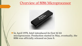
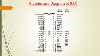
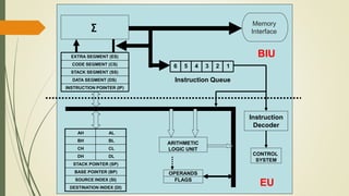
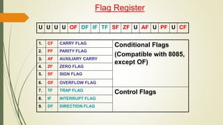
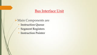
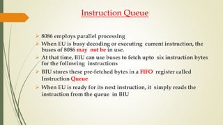
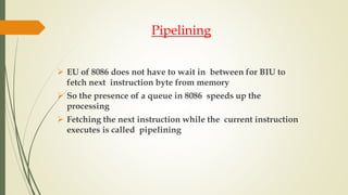
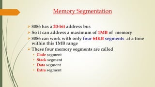
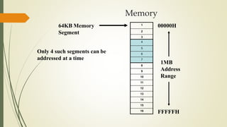
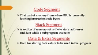
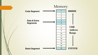
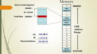
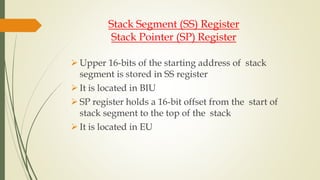
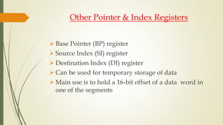
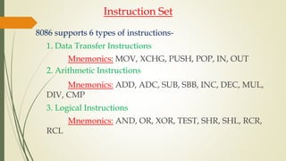
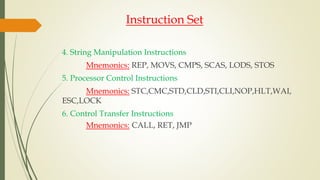
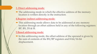
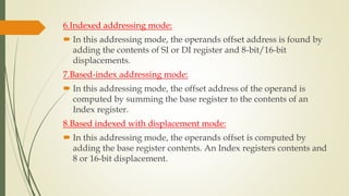
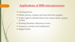
Dept. of Computer Science & Engineering
Islamic University-Bangladesh
Assignment on: Presentation on 8086 Microprocessor
Submitted To: Md.Atiqur Rahman
Assistant Professor , Dept. of CSE , Islamic University -Kushtia
Submitted By: Diponkor Bala
Roll: 1314021
Reg: 1136
Session:2013-2014
Overview of 8086 Microprocessor
In April 1978, Intel introduced its first 16 bit
microprocessor. Production started in May, eventually, the
8086 was officially released on June 8.
Features of 8086
The most prominent features of a 8086 microprocessor are as follows −
 It is a 16-bit microprocessor.
 8086 has a 20 bit address bus can access up to 2^20 (1 MB) memory
locations.
 It can support up to 64K I/O ports.
 It provides 14, 16 -bit registers.
 Word size is 16 bits.
 It has multiplexed address and data bus AD0- AD15 and
 A16 – A19.
 It requires single phase clock with 33% duty cycle to
provide internal timing.
Features of 8086
 8086 is designed to operate in two modes, Minimum and
Maximum.
 It can pre fetches up to 6 instruction bytes from memory
and queues them in order to speed up instruction execution.
 It requires +5V power supply.
 A 40 pin dual in line package.
 Address ranges from 00000H to FFFFFH
 Memory is byte addressable - Every byte has a separate
address.
Comparison between 8085 & 8086 Microprocessor
 Size − 8085 is 8-bit microprocessor, whereas 8086 is 16-bit
microprocessor.
 Address Bus − 8085 has 16-bit address bus while 8086 has 20-bit
address bus.
 Memory − 8085 can access up to 64Kb, whereas 8086 can access up to 1
Mb of memory.
 Instruction − 8085 doesn’t have an instruction queue, whereas 8086 has
an instruction queue.
 Pipelining − 8085 doesn’t support a pipelined architecture while 8086
supports a pipelined architecture.
 I/O − 8085 can address 2^8 = 256 I/O's, whereas 8086 can access 2^16 =
65,536 I/O's.
 Cost − The cost of 8085 is low whereas that of 8086 is high.
Architecture Diagram of 8086
AH AL
BH BL
CH CL
DH DL
STACK POINTER (SP)
BASE POINTER (BP)
SOURCE INDEX (SI)
DESTINATION INDEX (DI)
EXTRA SEGMENT (ES)
INSTRUCTION POINTER (IP)
DATA SEGMENT (DS)
STACK SEGMENT (SS)
CODE SEGMENT (CS)
CONTROL
SYSTEM
ARITHMETIC
LOGIC UNIT
FLAGS
6 5 4 3 2 1
Instruction Queue
OPERANDS
∑
Memory
Interface
EU
BIU
Instruction
Decoder
EU (Execution Unit)
Main components are-
• Instruction Decoder
• Control System
• Arithmetic Logic Unit
• General Purpose Registers
• Flag Register
• Pointer & Index registers
Instruction Decoder
 Translates instructions fetched from memory into a series of actions
which EU carries out
Control System
 Generates timing and control signals to perform the internal
operations of the microprocessor
Arithmetic Logic Unit
 EU has a 16-bit ALU which can ADD, SUBTRACT, AND, OR,
increment, decrement, complement or shift binary numbers
 EU has 8 general
purpose registers
 Can be individually
used for storing 8-bit
data
 AL register is also
called Accumulator
 Two registers can also
be combined to form
16-bit registers
 The valid register pairs
are – AX, BX, CX, DX
AH AL
BH BL
CH CL
DH DL
AH AL AX
BH BL BX
CH CL CX
DH DL DX
General Purpose Registers
8086 has a 16-bit flag register
Contains 9 active flags
There are two types of flags in 8086
• Conditional flags – six flags, set or reset
by EU on the basis of results of some
arithmetic operations
• Control flags – three flags, used to control
certain operations of the processor
FlagRegister
U U U U OF DF IF TF SF ZF U AF U PF U CF
1. CF CARRY FLAG
Conditional Flags
(Compatible with 8085,
except OF)
2. PF PARITY FLAG
3. AF AUXILIARY CARRY
4. ZF ZERO FLAG
5. SF SIGN FLAG
6. OF OVERFLOW FLAG
7. TF TRAP FLAG
Control Flags
8. IF INTERRUPT FLAG
9. DF DIRECTION FLAG
Flag Register
Bus Interface Unit
Main Components are
• Instruction Queue
• Segment Registers
• Instruction Pointer
Instruction Queue
 8086 employs parallel processing
 When EU is busy decoding or executing current instruction, the
buses of 8086 may not be in use.
 At that time, BIU can use buses to fetch upto six instruction bytes
for the following instructions
 BIU stores these pre-fetched bytes in a FIFO register called
Instruction Queue
 When EU is ready for its next instruction, it simply reads the
instruction from the queue in BIU
Pipelining
 EU of 8086 does not have to wait in between for BIU to
fetch next instruction byte from memory
 So the presence of a queue in 8086 speeds up the
processing
 Fetching the next instruction while the current instruction
executes is called pipelining
Memory Segmentation
 8086 has a 20-bit address bus
 So it can address a maximum of 1MB of memory
 8086 can work with only four 64KB segments at a time
within this 1MB range
 These four memory segments are called
• Code segment
• Stack segment
• Data segment
• Extra segment
7
6
5
4
Memory
00000H
FFFFFH
1MB
Address
Range
64KB Memory
Segment
Only 4 such segments can be
addressed at a time
1
2
3
4
5
6
7
8
9
10
11
12
13
14
15
16
Code Segment
 That part of memory from where BIU is currently
fetching instruction code bytes
Stack Segment
 A section of memory set aside to store addresses
and data while a subprogram executes
Data & Extra Segments
 Used for storing data values to be used in the program
1
2
3
4
5
6
7
8
9
10
11
12
13
14
15
16
Memory
00000H
FFFFFH
1MB
Address
Range
Code Segment
Stack Segment
Data & Extra
Segments
Segment Registers
hold the upper 16-bits of the starting address for
each of the segments
The four segment registers are
• CS (Code Segment register)
• DS (Data Segment register)
• SS (Stack Segment register)
• ES (Extra Segment register)
1
Code Segment
3
4
Data Segment
Extra Segment
7
8
9
10
11
12
13
14
15
Stack Segment
Memory
00000H
FFFFFH
1MB
Address
Range
StartingAddresses
ofSegments
1000 0H
4000 0H
F000 0H
CS
DS
ES 5000 0H
SS
 Address of a segment is of 20-bits
 A segment register stores only upper 16- bits
 BIU always inserts zeros for the lowest 4- bits of the 20-bit
starting address.
 E.g. if CS = 348AH, then the code segment will
start at 348A0H
 A 64-KB segment can be located anywhere in the memory,
but will start at an address with zeros in the lowest 4-bits
Instruction Pointer (IP) Register
 a 16-bit register
 Holds 16-bit offset, of the next instruction byte in
the code segment
 BIU uses IP and CS registers to generate the 20-bit
address of the instruction to be fetched from
memory
1
Data
Segment
3
4
Code
Segment
Extra
Segment
7
8
9
10
11
12
13
14
15
Stack
Segment
Memory
00000H
FFFFFH
1MB
Address
Range
38AB4 H
CS
IP
Physical Address
Start of Code Segment
Code Byte MOV AL, BL38AB4H
348A0H
IP = 4214H
348A0 H
+ 4214 H
Stack Segment (SS) Register
Stack Pointer (SP) Register
 Upper 16-bits of the starting address of stack
segment is stored in SS register
 It is located in BIU
 SP register holds a 16-bit offset from the start of
stack segment to the top of the stack
 It is located in EU
Other Pointer & Index Registers
 Base Pointer (BP) register
 Source Index (SI) register
 Destination Index (DI) register
 Can be used for temporary storage of data
 Main use is to hold a 16-bit offset of a data word in
one of the segments
Instruction Set
8086 supports 6 types of instructions-
1. Data Transfer Instructions
Mnemonics: MOV, XCHG, PUSH, POP, IN, OUT
2. Arithmetic Instructions
Mnemonics: ADD, ADC, SUB, SBB, INC, DEC, MUL,
DIV, CMP
3. Logical Instructions
Mnemonics: AND, OR, XOR, TEST, SHR, SHL, RCR,
RCL
Instruction Set
4. String Manipulation Instructions
Mnemonics: REP, MOVS, CMPS, SCAS, LODS, STOS
5. Processor Control Instructions
Mnemonics: STC,CMC,STD,CLD,STI,CLI,NOP,HLT,WAI,
ESC,LOCK
6. Control Transfer Instructions
Mnemonics: CALL, RET, JMP
Addressing Modes
The different ways in which a source operand is denoted in an
instruction is known as addressing modes.
There are 8 different addressing modes in 8086 programming −
1.Immediate addressing mode:
The addressing mode in which the data operand is a part of the
instruction itself is known as immediate addressing mode.
2.Register addressing mode:
It means that the register is the source of an operand for an
instruction.
3. Direct addressing mode:
 The addressing mode in which the effective address of the memory
location is written directly in the instruction.
4.Register indirect addressing mode:
 This addressing mode allows data to be addressed at any memory
location through an offset address held in any of the following registers:
BP, BX, DI & SI.
5.Based addressing mode:
 In this addressing mode, the offset address of the operand is given by
the sum of contents of the BX/BP registers and 8-bit/16-bit
displacement.
6.Indexed addressing mode:
 In this addressing mode, the operands offset address is found by
adding the contents of SI or DI register and 8-bit/16-bit
displacements.
7.Based-index addressing mode:
 In this addressing mode, the offset address of the operand is
computed by summing the base register to the contents of an
Index register.
8.Based indexed with displacement mode:
 In this addressing mode, the operands offset is computed by
adding the base register contents. An Index registers contents and
8 or 16-bit displacement.
Applications of 8086 microprocessor
 Gaming devices.
 Mobile phones, Laptops and some electronic gadgets.
 Traffic Lights Controller (One of my seniors made a project
on this)
 Washing Machines, Microwave ovens.
 Frequency counters and synthesizers.
 Digital Clocks.
Presentation on 8086 microprocessor

Presentation on 8086 microprocessor

  • 1.
    Dept. of ComputerScience & Engineering Islamic University-Bangladesh Assignment on: Presentation on 8086 Microprocessor Submitted To: Md.Atiqur Rahman Assistant Professor , Dept. of CSE , Islamic University -Kushtia Submitted By: Diponkor Bala Roll: 1314021 Reg: 1136 Session:2013-2014
  • 2.
    Overview of 8086Microprocessor In April 1978, Intel introduced its first 16 bit microprocessor. Production started in May, eventually, the 8086 was officially released on June 8.
  • 3.
    Features of 8086 Themost prominent features of a 8086 microprocessor are as follows −  It is a 16-bit microprocessor.  8086 has a 20 bit address bus can access up to 2^20 (1 MB) memory locations.  It can support up to 64K I/O ports.  It provides 14, 16 -bit registers.  Word size is 16 bits.  It has multiplexed address and data bus AD0- AD15 and  A16 – A19.  It requires single phase clock with 33% duty cycle to provide internal timing.
  • 4.
    Features of 8086 8086 is designed to operate in two modes, Minimum and Maximum.  It can pre fetches up to 6 instruction bytes from memory and queues them in order to speed up instruction execution.  It requires +5V power supply.  A 40 pin dual in line package.  Address ranges from 00000H to FFFFFH  Memory is byte addressable - Every byte has a separate address.
  • 5.
    Comparison between 8085& 8086 Microprocessor  Size − 8085 is 8-bit microprocessor, whereas 8086 is 16-bit microprocessor.  Address Bus − 8085 has 16-bit address bus while 8086 has 20-bit address bus.  Memory − 8085 can access up to 64Kb, whereas 8086 can access up to 1 Mb of memory.  Instruction − 8085 doesn’t have an instruction queue, whereas 8086 has an instruction queue.  Pipelining − 8085 doesn’t support a pipelined architecture while 8086 supports a pipelined architecture.  I/O − 8085 can address 2^8 = 256 I/O's, whereas 8086 can access 2^16 = 65,536 I/O's.  Cost − The cost of 8085 is low whereas that of 8086 is high.
  • 6.
  • 7.
    AH AL BH BL CHCL DH DL STACK POINTER (SP) BASE POINTER (BP) SOURCE INDEX (SI) DESTINATION INDEX (DI) EXTRA SEGMENT (ES) INSTRUCTION POINTER (IP) DATA SEGMENT (DS) STACK SEGMENT (SS) CODE SEGMENT (CS) CONTROL SYSTEM ARITHMETIC LOGIC UNIT FLAGS 6 5 4 3 2 1 Instruction Queue OPERANDS ∑ Memory Interface EU BIU Instruction Decoder
  • 8.
    EU (Execution Unit) Maincomponents are- • Instruction Decoder • Control System • Arithmetic Logic Unit • General Purpose Registers • Flag Register • Pointer & Index registers
  • 9.
    Instruction Decoder  Translatesinstructions fetched from memory into a series of actions which EU carries out Control System  Generates timing and control signals to perform the internal operations of the microprocessor Arithmetic Logic Unit  EU has a 16-bit ALU which can ADD, SUBTRACT, AND, OR, increment, decrement, complement or shift binary numbers
  • 10.
     EU has8 general purpose registers  Can be individually used for storing 8-bit data  AL register is also called Accumulator  Two registers can also be combined to form 16-bit registers  The valid register pairs are – AX, BX, CX, DX AH AL BH BL CH CL DH DL AH AL AX BH BL BX CH CL CX DH DL DX General Purpose Registers
  • 11.
    8086 has a16-bit flag register Contains 9 active flags There are two types of flags in 8086 • Conditional flags – six flags, set or reset by EU on the basis of results of some arithmetic operations • Control flags – three flags, used to control certain operations of the processor FlagRegister
  • 12.
    U U UU OF DF IF TF SF ZF U AF U PF U CF 1. CF CARRY FLAG Conditional Flags (Compatible with 8085, except OF) 2. PF PARITY FLAG 3. AF AUXILIARY CARRY 4. ZF ZERO FLAG 5. SF SIGN FLAG 6. OF OVERFLOW FLAG 7. TF TRAP FLAG Control Flags 8. IF INTERRUPT FLAG 9. DF DIRECTION FLAG Flag Register
  • 13.
    Bus Interface Unit MainComponents are • Instruction Queue • Segment Registers • Instruction Pointer
  • 14.
    Instruction Queue  8086employs parallel processing  When EU is busy decoding or executing current instruction, the buses of 8086 may not be in use.  At that time, BIU can use buses to fetch upto six instruction bytes for the following instructions  BIU stores these pre-fetched bytes in a FIFO register called Instruction Queue  When EU is ready for its next instruction, it simply reads the instruction from the queue in BIU
  • 15.
    Pipelining  EU of8086 does not have to wait in between for BIU to fetch next instruction byte from memory  So the presence of a queue in 8086 speeds up the processing  Fetching the next instruction while the current instruction executes is called pipelining
  • 16.
    Memory Segmentation  8086has a 20-bit address bus  So it can address a maximum of 1MB of memory  8086 can work with only four 64KB segments at a time within this 1MB range  These four memory segments are called • Code segment • Stack segment • Data segment • Extra segment
  • 17.
    7 6 5 4 Memory 00000H FFFFFH 1MB Address Range 64KB Memory Segment Only 4such segments can be addressed at a time 1 2 3 4 5 6 7 8 9 10 11 12 13 14 15 16
  • 18.
    Code Segment  Thatpart of memory from where BIU is currently fetching instruction code bytes Stack Segment  A section of memory set aside to store addresses and data while a subprogram executes Data & Extra Segments  Used for storing data values to be used in the program
  • 19.
  • 20.
    Segment Registers hold theupper 16-bits of the starting address for each of the segments The four segment registers are • CS (Code Segment register) • DS (Data Segment register) • SS (Stack Segment register) • ES (Extra Segment register)
  • 21.
    1 Code Segment 3 4 Data Segment ExtraSegment 7 8 9 10 11 12 13 14 15 Stack Segment Memory 00000H FFFFFH 1MB Address Range StartingAddresses ofSegments 1000 0H 4000 0H F000 0H CS DS ES 5000 0H SS
  • 22.
     Address ofa segment is of 20-bits  A segment register stores only upper 16- bits  BIU always inserts zeros for the lowest 4- bits of the 20-bit starting address.  E.g. if CS = 348AH, then the code segment will start at 348A0H  A 64-KB segment can be located anywhere in the memory, but will start at an address with zeros in the lowest 4-bits
  • 23.
    Instruction Pointer (IP)Register  a 16-bit register  Holds 16-bit offset, of the next instruction byte in the code segment  BIU uses IP and CS registers to generate the 20-bit address of the instruction to be fetched from memory
  • 24.
  • 25.
    Stack Segment (SS)Register Stack Pointer (SP) Register  Upper 16-bits of the starting address of stack segment is stored in SS register  It is located in BIU  SP register holds a 16-bit offset from the start of stack segment to the top of the stack  It is located in EU
  • 26.
    Other Pointer &Index Registers  Base Pointer (BP) register  Source Index (SI) register  Destination Index (DI) register  Can be used for temporary storage of data  Main use is to hold a 16-bit offset of a data word in one of the segments
  • 27.
    Instruction Set 8086 supports6 types of instructions- 1. Data Transfer Instructions Mnemonics: MOV, XCHG, PUSH, POP, IN, OUT 2. Arithmetic Instructions Mnemonics: ADD, ADC, SUB, SBB, INC, DEC, MUL, DIV, CMP 3. Logical Instructions Mnemonics: AND, OR, XOR, TEST, SHR, SHL, RCR, RCL
  • 28.
    Instruction Set 4. StringManipulation Instructions Mnemonics: REP, MOVS, CMPS, SCAS, LODS, STOS 5. Processor Control Instructions Mnemonics: STC,CMC,STD,CLD,STI,CLI,NOP,HLT,WAI, ESC,LOCK 6. Control Transfer Instructions Mnemonics: CALL, RET, JMP
  • 29.
    Addressing Modes The differentways in which a source operand is denoted in an instruction is known as addressing modes. There are 8 different addressing modes in 8086 programming − 1.Immediate addressing mode: The addressing mode in which the data operand is a part of the instruction itself is known as immediate addressing mode. 2.Register addressing mode: It means that the register is the source of an operand for an instruction.
  • 30.
    3. Direct addressingmode:  The addressing mode in which the effective address of the memory location is written directly in the instruction. 4.Register indirect addressing mode:  This addressing mode allows data to be addressed at any memory location through an offset address held in any of the following registers: BP, BX, DI & SI. 5.Based addressing mode:  In this addressing mode, the offset address of the operand is given by the sum of contents of the BX/BP registers and 8-bit/16-bit displacement.
  • 31.
    6.Indexed addressing mode: In this addressing mode, the operands offset address is found by adding the contents of SI or DI register and 8-bit/16-bit displacements. 7.Based-index addressing mode:  In this addressing mode, the offset address of the operand is computed by summing the base register to the contents of an Index register. 8.Based indexed with displacement mode:  In this addressing mode, the operands offset is computed by adding the base register contents. An Index registers contents and 8 or 16-bit displacement.
  • 32.
    Applications of 8086microprocessor  Gaming devices.  Mobile phones, Laptops and some electronic gadgets.  Traffic Lights Controller (One of my seniors made a project on this)  Washing Machines, Microwave ovens.  Frequency counters and synthesizers.  Digital Clocks.