Introduction:
⚫ Direct MemoryAccess (DMA) is a method
of allowing data to be moved from one
location to another in a computer without
intervention from the central processor (CPU).
⚫It is also a fast way of transferring data
within (and sometimes between)
computer.
⚫The DMA I/O technique provides direct access
to the memory while the
microprocessor is temporarily disabled.
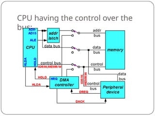
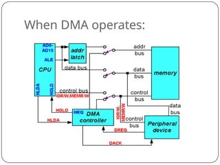
⚫The DMA controller temporarily borrows
the address bus, data bus and control bus
from the microprocessor and transfers the
data directly from the external devices to
3.
Basic DMA Operation:
⚫Twocontrol signals are used
to
request
and
acknowledge a direct memory access
(DMA) transfer in the microprocessor-based
system.
⚫TheHOLD signal as an input(tothe
processor) is used to request a DMA action.
⚫TheHLDA signal as an outputthat
acknowledges the DMA action.
⚫ When the processor recognizes the hold, itstops
its execution and enters hold cycles.
4.
Cont.,
⚫ HOLD inputhas higher priority than INTR or NMI.
⚫The only microprocessor pin that has a
higher priority than a HOLD is the
RESET pin.
⚫HLDA
becomes
activ
e processorhas
placed
to
indicate its
buses
that
the at
high-
impedance
state.
5.
Basic DMA Definitions:
⚫Directmemory accesses normally occur
between an I/O device and memory without
the use of the microprocessor.
⚫A DMA read transfers data from the
memory to the I/O device.
⚫A DMA write transfers data from an I/O
device to memory.
⚫The system contains separate memory and
I/O control signals.
⚫Hence the Memory & the I/O are
controlled simultaneously
6.
⚫The DMA controllerprovides memory with its
address, and the controller signal selects the
I/O device during the transfer.
⚫Data transfer speed is determined by speed of
the memory device or a DMA controller.
⚫In many cases, the DMA controller slows the speed
of the system when transfers occur.
⚫The serial PCI (Peripheral Component
Interface) Express bus transfers data at rates
exceeding DMA transfers.
⚫This in modern systems has made DMA is
less important.
7.
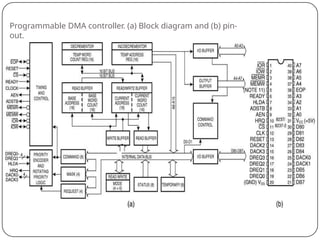
The 8237 DMAController
⚫The 8237 supplies memory & I/O with
control signals and memory address
information during the DMA transfer.
⚫It is actually a special-purpose
microprocessor whose job is high-speed
data transfer between memory and I/O
⚫8237 is nota discrete componentin
modern microprocessor-based systems.
⚫It appears within many system controller
chip sets
⚫8237 is a four-channel device compatible
with 8086/8088, adequate for small
systems.
⚫Expandable to any number of DMA
channel inputs
⚫8237 is capable of DMA transfers at rates
up to 1.6MB per second.
⚫Each channel is capable of addressing
8237 Internal Registers
CAR
⚫Thecurrent address register holds a 16-
bit memory address used for the DMA
transfer.
⚫Each channel has its own current
address register for this purpose.
⚫When a byte of data is transferred during a
DMA
operation, CAR is either incremented
or
is
decremented depending on how
it programmed.
13.
CWCR
⚫The current wordcount register
programs a to
transferred
channel for the numberof
bytes during a DMA action.
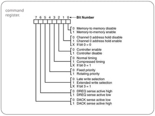
CR
⚫The command register programsthe
operation of the 8237 DMA controller.
⚫The register uses bit position 0 to select
the memory-to-memory DMA transfer
mode.
⚫Memory-to-memory DMA transfers use
DMA channel 0 to hold the source address
⚫DMA channel 1 holds the destination address
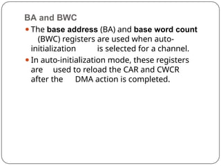
BA and BWC
⚫Thebase address (BA) and base word count
(BWC) registers are used when auto-
initialization is selected for a channel.
⚫In auto-initialization mode, these registers
are used to reload the CAR and CWCR
after the DMA action is completed.
16.
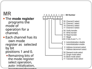
⚫The mode register
programsthe
mode of
operation for a
channel.
⚫Each channel has its
own mode
register as selected
by bit
positions 1 and 0.
⚫Remaining bits of
the mode register
select operation,
auto- initialization,
MR
17.
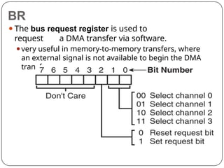
⚫The bus requestregister is used to
request a DMA transfer via software.
⚫very useful in memory-to-memory transfers, where
an external signal is not available to begin the DMA
transfer
BR
18.
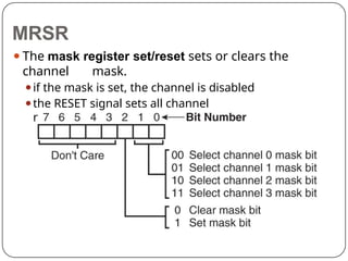
⚫The mask registerset/reset sets or clears the
channel mask.
⚫if the mask is set, the channel is disabled
⚫the RESET signal sets all channel
masks to disable them
MRSR
19.
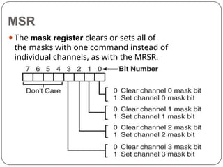
⚫The mask registerclears or sets all of
the masks with one command instead of
individual channels, as with the MRSR.
MSR
20.
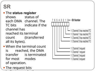
⚫The status register
showsstatus of
each DMA channel. The
TC bits indicate if the
channel has
reached its terminal
count (transferred
all its bytes).
⚫When the terminal count
is reached, the DMA
transfer is terminated
for most modes
of operation.
⚫The request bits
SR
21.
Master clear
⚫Acts exactlythe same as the RESET signal to the
8237.
⚫As with the RESET signal, this command
disables all channels
Clear mask register
⚫Enables all four DMA channels.
Clear the first/last flip-flop
⚫Clears the first/last (F/L) flip-flop within 8237.
⚫The F/L flip-flop selects which byte (low or high
order) is read/written in the current address
and current count registers.
⚫if F/L = 0, the low-order byte is selected
⚫if F/L = 1, the high-order byte is selected
22.
⚫Memory-to-
memory
transfer is much
more
powerfulthan the automatically
repeated MOVSB instruction.
⚫most modern chip sets do not support
the memory-to-memory feature
⚫8237 requires only 2.0 µs per byte, which
is over twice as fast the existing data
transfer.