Downloaded 612 times
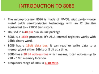
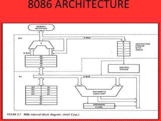
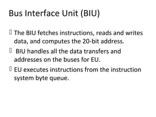

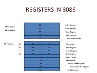
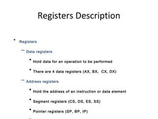

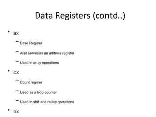
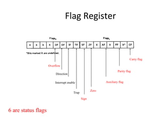


The 8086 microprocessor has an architecture that separates it into a Bus Interface Unit (BIU) and Execution Unit (EU). The BIU fetches instructions and data from memory and handles address calculation on the buses. The EU decodes and executes instructions using its 16-bit ALU. The 8086 has 16 general purpose registers including 4 data registers (AX, BX, CX, DX) and segment/pointer registers. It also contains a flag register for storing status flags. The 8086 can queue up to 6 bytes of upcoming instructions to improve performance.