Downloaded 52 times

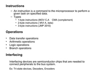


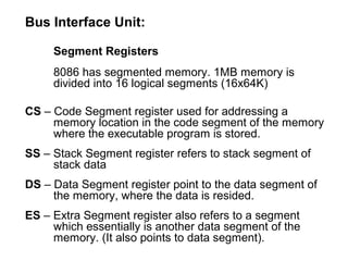
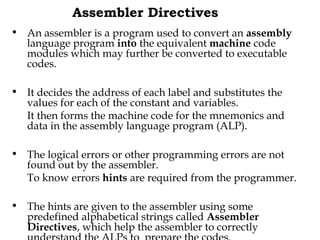
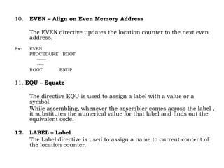
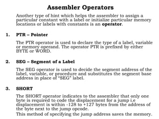
![4. TYPE
The TYPE operator directs the assembler to decide the data type
of the specified label and replaces the ‘TYPE’ label by the
decided data type.
Ex: MOV AX, TYPE STRING
moves the value 0002h in AX.
5. GLOBAL
The labels, variables, constants or procedures declared GLOBAL
may be used by other modules of the program.
Ex: ROUTINE PROC GLOBAL
6. ‘ + & - ‘ Operators
These operators represent arithmetic addition and subtraction
respectively and are typically used to add or subtract
displacement (8 or 16 bit) to base or index registers or stack or
base pointers.
Ex: MOV AL, [SI +2]](https://image.slidesharecdn.com/22885850-microprocessor-170829131017/85/microprocessor-22-320.jpg)
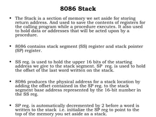
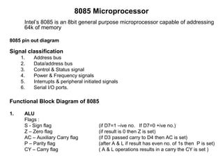
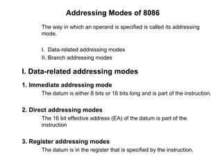
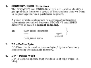
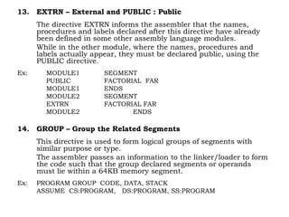
![2. Passing parameters in General Memory
DATA SEGMENT
BCD_INPUT DB 20H
BIN_VALUE DB ?
DATA ENDS
CODE SEGMENT
---
CALL BCD_BIN ; call procedure BCD_BIN
---
NOP
;Procedure to convert BCD to Binary no.
BCD_BIN PROC NEAR
----
MOV AL, BCD_INPUT ;Load input from memory
------
MOV [DI], AL ; Store result in memory
RET
BCD_BIN ENDP
----
CODE ENDS](https://image.slidesharecdn.com/22885850-microprocessor-170829131017/85/microprocessor-27-320.jpg)
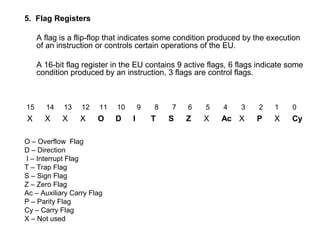
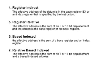
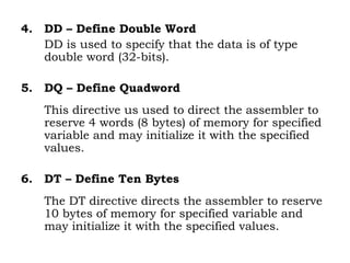
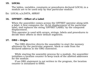
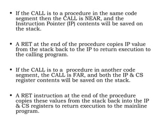
![;Procedure to convert BCD to Binary no.
BCD_BIN PROC NEAR
----
MOV AL, [SI] ;Load input from memory
------
MOV [DI], AL ; Store result in memory
----
RET
BCD_BIN ENDP
----
CODE ENDS
END](https://image.slidesharecdn.com/22885850-microprocessor-170829131017/85/microprocessor-29-320.jpg)

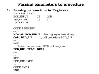
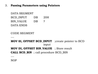
The document discusses microprocessors, their architecture, instructions, operations, interfacing and the 8085 and 8086 microprocessors. It provides details on the functional blocks, registers, addressing modes, procedures, calling conventions, and stack usage of the 8086 microprocessor. It also describes various assembler directives, operators, and concepts like logical segments, procedures, and passing parameters in registers vs memory for procedures.