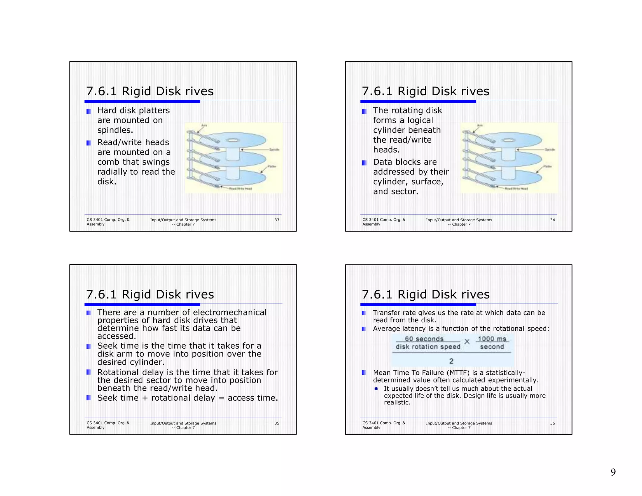
The document is a chapter about input/output and storage systems from a computer organization and assembly course. It discusses various I/O architectures like programmed I/O, interrupt-driven I/O, DMA, and channel I/O. It also covers data transmission modes, magnetic disk technology, hard disks, floppy disks, and file allocation tables. The key topics are I/O methods and architectures, storage media formats, RAID, data compression algorithms, and how I/O systems work.
discuss the drawbacks of programmed and interrupt driven io and des.pdfinfo998421
discuss the drawbacks of programmed and interrupt driven i/o and describe in general the
functionality of the DNA
Solution
Programmed I/O
Programmed I/O (PIO) refers to data transfers initiated by a CPU under driver software control
to access registers or memory on a device.
The CPU issues a command then waits for I/O operations to be complete. As the CPU is faster
than the I/O module, the problem with programmed I/O is that the CPU has to wait a long time
for the I/O module of concern to be ready for either reception or transmission of data. The CPU,
while waiting, must repeatedly check the status of the I/O module, and this process is known as
Polling. As a result, the level of the performance of the entire system is severely degraded.
Programmed I/O basically works in these ways:
Interrupt
The CPU issues commands to the I/O module then proceeds with its normal work until
interrupted by I/O device on completion of its work.
For input, the device interrupts the CPU when new data has arrived and is ready to be retrieved
by the system processor. The actual actions to perform depend on whether the device uses I/O
ports, memory mapping.
For output, the device delivers an interrupt either when it is ready to accept new data or to
acknowledge a successful data transfer. Memory-mapped and DMA-capable devices usually
generate interrupts to tell the system they are done with the buffer.
Although Interrupt relieves the CPU of having to wait for the devices, but it is still inefficient in
data transfer of large amount because the CPU has to transfer the data word by word between I/O
module and memory.
The main limitation of programmed I/O and interrupt driven I/O is given below:
Programmed I/O
Each instructions selects one I/O device (by number) and transfers a single character (byte)
Example: microprocessor controlled video terminal.
Four registers: input status and character, output status and character.
Interrupt-driven I/O
Primary disadvantage of programmed I/O is that CPU spends most of its time in a tight loop
waiting for the device to become ready. This is called busy waiting.
With interrupt-driven I/O, the CPU starts the device and tells it to generate an interrupt when it is
finished.
Done by setting interrupt-enable bit in status register.
Still requires an interrupt for every character read or written.
Interrupting a running process is an expensive business (requires saving context).
Requires extra hardware (DMA controller chip).
All these limitation can be overcome by the Introduction of DMA (Direct Memory Access)
To write block of 32 bytes from memory address 100 to device 4
1. CPU writes 32, 100, 4 into the first three DMA registers (memory address, count, device
number)
2. CPU puts code for WRITE (say 1) into fourth (direction) DMA register, which signals DMA
controller to begin operation
3. Controller reads (via bus request as CPU would) byte 100 from memory
4. Controller makes I/O request to write to device 4
5. Controller increments m.
This slide deals with the Input-Output Channel of an IBM 370 computer. It includes three Block diagrams of the I-O channels as well as the Memory Unit with the Description of each and every diagrams.
Introduction – Multiple tasks and multiple processes – Multirate systems- Preemptive realtime operating systems- Priority based scheduling- Interprocess communication mechanisms – Evaluating operating system performance- power optimization strategies for processes –Example Real time operating systems-POSIX-Windows CE. – Distributed embedded systems – MPSoCs and shared memory multiprocessors. – Design Example – Audio player, Engine control unit – Video accelerator.
Similar to Chapter7_InputOutputStorageSystems.pptx (20)
UiPath Test Automation using UiPath Test Suite series, part 3DianaGray10
Welcome to UiPath Test Automation using UiPath Test Suite series part 3. In this session, we will cover desktop automation along with UI automation.
Topics covered:
UI automation Introduction,
UI automation Sample
Desktop automation flow
Pradeep Chinnala, Senior Consultant Automation Developer @WonderBotz and UiPath MVP
Deepak Rai, Automation Practice Lead, Boundaryless Group and UiPath MVP
Key Trends Shaping the Future of Infrastructure.pdfCheryl Hung
Keynote at DIGIT West Expo, Glasgow on 29 May 2024.
Cheryl Hung, ochery.com
Sr Director, Infrastructure Ecosystem, Arm.
The key trends across hardware, cloud and open-source; exploring how these areas are likely to mature and develop over the short and long-term, and then considering how organisations can position themselves to adapt and thrive.
"Impact of front-end architecture on development cost", Viktor TurskyiFwdays
I have heard many times that architecture is not important for the front-end. Also, many times I have seen how developers implement features on the front-end just following the standard rules for a framework and think that this is enough to successfully launch the project, and then the project fails. How to prevent this and what approach to choose? I have launched dozens of complex projects and during the talk we will analyze which approaches have worked for me and which have not.
Epistemic Interaction - tuning interfaces to provide information for AI supportAlan Dix
Paper presented at SYNERGY workshop at AVI 2024, Genoa, Italy. 3rd June 2024
https://alandix.com/academic/papers/synergy2024-epistemic/
As machine learning integrates deeper into human-computer interactions, the concept of epistemic interaction emerges, aiming to refine these interactions to enhance system adaptability. This approach encourages minor, intentional adjustments in user behaviour to enrich the data available for system learning. This paper introduces epistemic interaction within the context of human-system communication, illustrating how deliberate interaction design can improve system understanding and adaptation. Through concrete examples, we demonstrate the potential of epistemic interaction to significantly advance human-computer interaction by leveraging intuitive human communication strategies to inform system design and functionality, offering a novel pathway for enriching user-system engagements.
Let's dive deeper into the world of ODC! Ricardo Alves (OutSystems) will join us to tell all about the new Data Fabric. After that, Sezen de Bruijn (OutSystems) will get into the details on how to best design a sturdy architecture within ODC.
Kubernetes & AI - Beauty and the Beast !?! @KCD Istanbul 2024Tobias Schneck
As AI technology is pushing into IT I was wondering myself, as an “infrastructure container kubernetes guy”, how get this fancy AI technology get managed from an infrastructure operational view? Is it possible to apply our lovely cloud native principals as well? What benefit’s both technologies could bring to each other?
Let me take this questions and provide you a short journey through existing deployment models and use cases for AI software. On practical examples, we discuss what cloud/on-premise strategy we may need for applying it to our own infrastructure to get it to work from an enterprise perspective. I want to give an overview about infrastructure requirements and technologies, what could be beneficial or limiting your AI use cases in an enterprise environment. An interactive Demo will give you some insides, what approaches I got already working for real.
Essentials of Automations: Optimizing FME Workflows with ParametersSafe Software
Are you looking to streamline your workflows and boost your projects’ efficiency? Do you find yourself searching for ways to add flexibility and control over your FME workflows? If so, you’re in the right place.
Join us for an insightful dive into the world of FME parameters, a critical element in optimizing workflow efficiency. This webinar marks the beginning of our three-part “Essentials of Automation” series. This first webinar is designed to equip you with the knowledge and skills to utilize parameters effectively: enhancing the flexibility, maintainability, and user control of your FME projects.
Here’s what you’ll gain:
- Essentials of FME Parameters: Understand the pivotal role of parameters, including Reader/Writer, Transformer, User, and FME Flow categories. Discover how they are the key to unlocking automation and optimization within your workflows.
- Practical Applications in FME Form: Delve into key user parameter types including choice, connections, and file URLs. Allow users to control how a workflow runs, making your workflows more reusable. Learn to import values and deliver the best user experience for your workflows while enhancing accuracy.
- Optimization Strategies in FME Flow: Explore the creation and strategic deployment of parameters in FME Flow, including the use of deployment and geometry parameters, to maximize workflow efficiency.
- Pro Tips for Success: Gain insights on parameterizing connections and leveraging new features like Conditional Visibility for clarity and simplicity.
We’ll wrap up with a glimpse into future webinars, followed by a Q&A session to address your specific questions surrounding this topic.
Don’t miss this opportunity to elevate your FME expertise and drive your projects to new heights of efficiency.
GDG Cloud Southlake #33: Boule & Rebala: Effective AppSec in SDLC using Deplo...James Anderson
Effective Application Security in Software Delivery lifecycle using Deployment Firewall and DBOM
The modern software delivery process (or the CI/CD process) includes many tools, distributed teams, open-source code, and cloud platforms. Constant focus on speed to release software to market, along with the traditional slow and manual security checks has caused gaps in continuous security as an important piece in the software supply chain. Today organizations feel more susceptible to external and internal cyber threats due to the vast attack surface in their applications supply chain and the lack of end-to-end governance and risk management.
The software team must secure its software delivery process to avoid vulnerability and security breaches. This needs to be achieved with existing tool chains and without extensive rework of the delivery processes. This talk will present strategies and techniques for providing visibility into the true risk of the existing vulnerabilities, preventing the introduction of security issues in the software, resolving vulnerabilities in production environments quickly, and capturing the deployment bill of materials (DBOM).
Speakers:
Bob Boule
Robert Boule is a technology enthusiast with PASSION for technology and making things work along with a knack for helping others understand how things work. He comes with around 20 years of solution engineering experience in application security, software continuous delivery, and SaaS platforms. He is known for his dynamic presentations in CI/CD and application security integrated in software delivery lifecycle.
Gopinath Rebala
Gopinath Rebala is the CTO of OpsMx, where he has overall responsibility for the machine learning and data processing architectures for Secure Software Delivery. Gopi also has a strong connection with our customers, leading design and architecture for strategic implementations. Gopi is a frequent speaker and well-known leader in continuous delivery and integrating security into software delivery.
Accelerate your Kubernetes clusters with Varnish CachingThijs Feryn
A presentation about the usage and availability of Varnish on Kubernetes. This talk explores the capabilities of Varnish caching and shows how to use the Varnish Helm chart to deploy it to Kubernetes.
This presentation was delivered at K8SUG Singapore. See https://feryn.eu/presentations/accelerate-your-kubernetes-clusters-with-varnish-caching-k8sug-singapore-28-2024 for more details.
GraphRAG is All You need? LLM & Knowledge GraphGuy Korland
Guy Korland, CEO and Co-founder of FalkorDB, will review two articles on the integration of language models with knowledge graphs.
1. Unifying Large Language Models and Knowledge Graphs: A Roadmap.
https://arxiv.org/abs/2306.08302
2. Microsoft Research's GraphRAG paper and a review paper on various uses of knowledge graphs:
https://www.microsoft.com/en-us/research/blog/graphrag-unlocking-llm-discovery-on-narrative-private-data/
Dev Dives: Train smarter, not harder – active learning and UiPath LLMs for do...UiPathCommunity
💥 Speed, accuracy, and scaling – discover the superpowers of GenAI in action with UiPath Document Understanding and Communications Mining™:
See how to accelerate model training and optimize model performance with active learning
Learn about the latest enhancements to out-of-the-box document processing – with little to no training required
Get an exclusive demo of the new family of UiPath LLMs – GenAI models specialized for processing different types of documents and messages
This is a hands-on session specifically designed for automation developers and AI enthusiasts seeking to enhance their knowledge in leveraging the latest intelligent document processing capabilities offered by UiPath.
Speakers:
👨🏫 Andras Palfi, Senior Product Manager, UiPath
👩🏫 Lenka Dulovicova, Product Program Manager, UiPath
Dev Dives: Train smarter, not harder – active learning and UiPath LLMs for do...
Chapter7_InputOutputStorageSystems.pptx
1. CS 3401 Comp. Org.
& Assembly
Input/Output and Storage Systems
-- Chapter 7
1
Input/Output and Storage
Systems
CS 3401 Comp. Org. &
Assembly
Input/Output and Storage Systems
-- Chapter 7
2
Objectives
Understand how I/O systems work,
including I/O methods and architectures.
Become familiar with storage media, and
the differences in their respective formats.
Understand how RAID improves disk
performance and reliability.
Become familiar with the concepts of data
compression and applications suitable for
each type of compression algorithm.
CS 3401 Comp. Org. &
Assembly
Input/Output and Storage Systems
-- Chapter 7
3
7.1 Introduction
Data storage and retrieval is one of the
primary functions of computer systems.
One could easily make the argument that
computers are more useful to us as data storage
and retrieval devices than they are as
computational machines.
All computers have I/O devices connected
to them, and to achieve good performance
I/O should be kept to a minimum!
In studying I/O, we seek to understand the
different types of I/O devices as well as
how they work.
CS 3401 Comp. Org. &
Assembly
Input/Output and Storage Systems
-- Chapter 7
4
7.2 I/O and Performance
Sluggish I/O throughput can have a ripple
effect, dragging down overall system
performance.
This is especially true when virtual memory is
involved.
The fastest processor in the world is of little
use if it spends most of its time waiting for
data.
If we really understand what’s happening in
a computer system we can make the best
possible use of its resources.
1
2. CS 3401 Comp. Org. &
Assembly
Input/Output and Storage Systems
-- Chapter 7
5
7.3 Amdahl’s Law
The overall performance of a system is a result of the
interaction of all of its components.
System performance is most effectively improved
when the performance of the most heavily used
components is improved.
This idea is quantified by Amdahl’s Law:
where
S is the overall speedup
f is the fraction of work performed by
a faster component
k is the speedup of a faster component.
CS 3401 Comp. Org. &
Assembly
Input/Output and Storage Systems
-- Chapter 7
6
7.3 Amdahl’s Law
Amdahl’s Law gives us a handy way to estimate the
performance improvement we can expect when we
upgrade a system component.
Example: On a large system,
suppose we can upgrade a CPU to make it 50% faster
for $10,000 or upgrade its disk drives for $7,000 to
make them 2.5 times faster (250% faster).
Processes spend 70% of their time running in the
CPU and 30% of their time waiting for disk service.
An upgrade of which component would offer the
greater benefit for the lesser cost?
CS 3401 Comp. Org. &
Assembly
Input/Output and Storage Systems
-- Chapter 7
7
7.3 Amdahl’s Law
The processor option offers a 130% speedup:
And the disk drive option gives a 122% speedup:
Each 1% of improvement for the processor costs
$333, and for the disk a 1% improvement costs $318.
Should price/performance be your onlyconcern?
CS 3401 Comp. Org. &
Assembly
Input/Output and Storage Systems
-- Chapter 7
8
7.3 Amdahl’s Law
2
3. CS 3401 Comp. Org. &
Assembly
Input/Output and Storage Systems
-- Chapter 7
9
7.4 I/O Architectures
We define input/output as a subsystem of
components that moves coded data between external
devices and a host system (CPU, main memory).
I/O subsystems include:
Blocks of main memory that are devoted to I/O
functions.
Buses that move data into and out of the system.
Control modules in the host and in peripheral devices
Interfaces to external components such as keyboards
and disks.
Cabling or communications links between the host
system and its peripherals.
CS 3401 Comp. Org. &
Assembly
Input/Output and Storage Systems
-- Chapter 7
10
7.4 Model I/O Configuration
CS 3401 Comp. Org. &
Assembly
Input/Output and Storage Systems
-- Chapter 7
11
1. I/O Control Methods
I/O can be controlled in four general ways.
1. Programmed I/O reserves a register for each I/O
device. Each register is continually polled to
detect data arrival.
2. Interrupt-Driven I/O allows the CPU to do other
things until I/O is requested.
3. Direct Memory Access (DMA) offloads I/O
processing to a special-purpose chip that takes
care of the details.
4. Channel I/O uses dedicated I/O processors.
CS 3401 Comp. Org. &
Assembly
Input/Output and Storage Systems
-- Chapter 7
12
7.4.1 Programmed (Polled) I/O
Reserves a register for each I/O device
Polling -- CPU continually monitors each register waiting for
data
If data ready condition is true, CPU processes the data
Pros:
We have programmatic control over the behavior of each I/O
device
Adjustments can be made to the number and types of devices,
polling priorities and intervals.
Con:
Constant register polling -- CPU is in a busy wait state
Best suited for special-purpose systems
Automated teller machines and systems
Monitoring or control systems
3
4. CS 3401 Comp. Org. &
Assembly
Input/Output and Storage Systems
-- Chapter 7
13
7.4.1 Interrupt-Driven I/O
This is an idealized I/O subsystem that uses
interrupts.
Each device connects its interrupt line to the
interrupt controller.
The controller
signals the CPU
when any of the
interrupt lines are
asserted.
CS 3401 Comp. Org. &
Assembly
Input/Output and Storage Systems
-- Chapter 7
14
7.4.1 Interrupt-Driven I/O
Recall from Chapter 4 that in a system that
uses interrupts, the status of the interrupt
signal is checked at the top of the fetch-
decode-execute cycle.
The particular code that is executed
whenever an interrupt occurs is determined
by a set of addresses called interrupt
vectors that are stored in low memory.
The system state is saved before the
interrupt service routine is executed and is
restored afterward.
CS 3401 Comp. Org. &
Assembly
Input/Output and Storage Systems
-- Chapter 7
15
7.4.1 Interrupt-Driven I/O
I/O device send a request (interrupt)
to CPU for servicing
Interrupt flag – a bit in the flag
register to signal to CPU
Interrupt vectors – service routines
Service routines can be modified.
CS 3401 Comp. Org. &
Assembly
Input/Output and Storage Systems
-- Chapter 7
16
The Fetch-Decode-Interrupt Cycle with Interrupt
Checking Processing an Interrupt
4
5. CS 3401 Comp. Org. &
Assembly
Input/Output and Storage Systems
-- Chapter 7
17
7.4.1 Direct Memory Access (DMA)
Notice that the DMA
and the CPU share
the bus.
CPU provides DMA
with location of the
bytes, # bytes to be
transferred,
destination device or
memory address
The DMA runs at a
higher priority and
steals memory cycles
from the CPU.
CS 3401 Comp. Org. &
Assembly
Input/Output and Storage Systems
-- Chapter 7
18
7.4.1 Direct Memory Access (DMA)
CS 3401 Comp. Org. &
Assembly
Input/Output and Storage Systems
-- Chapter 7
19
7.4.1 Channel I/O
Very large systems employ channel I/O.
Channel I/O consists of one or more I/O
processors (IOPs) that control various
channel paths.
Slower devices such as terminals and
printers are combined (multiplexed) into a
single faster channel.
On IBM mainframes, multiplexed channels
are called multiplexor channels, the faster
ones are called selector channels.
CS 3401 Comp. Org. &
Assembly
Input/Output and Storage Systems
-- Chapter 7
20
7.4.1 Channel I/O
Channel I/O is distinguished from DMA by
the intelligence of the IOPs.
The IOP negotiates protocols, issues device
commands, translates storage coding to
memory coding, and can transfer entire
files or groups of files independent of the
host CPU.
The host has only to create the program
instructions for the I/O operation and tell
the IOP where to find them.
5
6. CS 3401 Comp. Org. &
Assembly
Input/Output and Storage Systems
-- Chapter 7
21
7.4.1 Channel I/O Configuration
CS 3401 Comp. Org. &
Assembly
Input/Output and Storage Systems
-- Chapter 7
22
7.4.2 Character I/O Versus
Block I/O
Character I/O devices process one byte (or
character) at a time.
Examples include modems, keyboards, and
mice.
Keyboards are usually connected through an
interrupt-driven I/O system.
Block I/O devices handle bytes in groups.
Most mass storage devices (disk and tape)
are block I/O devices.
Block I/O systems are most efficiently
connected through DMA or channel I/O.
CS 3401 Comp. Org. &
Assembly
Input/Output and Storage Systems
-- Chapter 7
23
7.4.3 I/O Bus Operations
I/O buses, unlike memory buses, operate
asynchronously. Requests for bus access must be
arbitrated among the devices involved.
Bus control lines activate the devices when they are
needed, raise signals when errors have occurred, and
reset devices when necessary.
The number of data lines is the width of the bus.
A bus clock coordinates activities and provides bit cell
boundaries.
CS 3401 Comp. Org. &
Assembly
Input/Output and Storage Systems
-- Chapter 7
24
7.4.3 System Bus
6
7. CS 3401 Comp. Org. &
Assembly
Input/Output and Storage Systems
-- Chapter 7
25
7.4.3 System Bus
This is a generic DMA configuration
showing how the DMA circuit
connects to a data bus.
CS 3401 Comp. Org. &
Assembly
Input/Output and Storage Systems
-- Chapter 7
26
7.4.3 I/O Bus Connections
CS 3401 Comp. Org. &
Assembly
Input/Output and Storage Systems
-- Chapter 7
27
7.4.3 Write Data to Disk
1. The DMA circuit places the address of the disk controller on the
address lines, and raises (asserts) the Request and Write
signals.
2. With the Request signal asserted, decoder circuits in the
controller interrogate the address lines.
3. Upon sensing its own address, the decoder enables the disk
control circuits. If the disk is available for writing data, the
controller asserts a signal on the Ready line. At this point, the
handshake between the DMA and the controller is complete. With
the Ready signal raised, no other devices may use the bus.
4. The DMA circuits then place the data on the lines and lower the
Request signal.
5. When the disk controller sees the Request signal drop, it transfer
the byte from data lines to the disk buffer, and then lowers its
Ready signal.
CS 3401 Comp. Org. &
Assembly
Input/Output and Storage Systems
-- Chapter 7
28
7.4.3 Bus Timing Diagram
Timing diagrams define bus operation in detail.
7
8. CS 3401 Comp. Org. &
Assembly
Input/Output and Storage Systems
-- Chapter 7
29
7.5 Data Transmission Modes
Bytes can be conveyed
from one point to
another by sending
their encoding signals
simultaneously using
parallel data
transmission or by
sending them one bit
at a time in serial data
transmission
Parallel data
transmission for a
printer resembles the
signal protocol of a
memory bus:
CS 3401 Comp. Org. &
Assembly
Input/Output and Storage Systems
-- Chapter 7
30
7.5 Data Transmission Modes
In parallel data transmission, the interface
requires one conductor for each bit.
Parallel cables are fatter than serial cables.
Compared with parallel data interfaces,
serial communications interfaces:
Require fewer conductors.
Are less susceptible to attenuation.
Can transmit data farther and faster.
Serial communications interfaces are suitable fortime-
sensitive (isochronous) data such as voice and video.
Serial communications interfaces are suitable fortime-
sensitive (isochronous) data such as voice and video.
CS 3401 Comp. Org. &
Assembly
Input/Output and Storage Systems
-- Chapter 7
31
7.6 Magnetic Disk Technology
Magnetic disks offer large amounts of
durable storage that can be accessed
quickly.
Disk drives are called random (or direct)
access storage devices, because blocks of
data can be accessed according to their
location on the disk.
This term was coined when all other durable
storage (e.g., tape) was sequential.
Magnetic disk organization is shown on the
following slide.
CS 3401 Comp. Org. &
Assembly
Input/Output and Storage Systems
-- Chapter 7
32
7.6 Magnetic Disk Technology
Disk tracks are
numbered from the
outside edge,
starting with zero.
8
9. CS 3401 Comp. Org. &
Assembly
Input/Output and Storage Systems
-- Chapter 7
33
7.6.1 Rigid Disk rives
Hard disk platters
are mounted on
spindles.
Read/write heads
are mounted on a
comb that swings
radially to read the
disk.
CS 3401 Comp. Org. &
Assembly
Input/Output and Storage Systems
-- Chapter 7
34
7.6.1 Rigid Disk rives
The rotating disk
forms a logical
cylinder beneath
the read/write
heads.
Data blocks are
addressed by their
cylinder, surface,
and sector.
CS 3401 Comp. Org. &
Assembly
Input/Output and Storage Systems
-- Chapter 7
35
7.6.1 Rigid Disk rives
There are a number of electromechanical
properties of hard disk drives that
determine how fast its data can be
accessed.
Seek time is the time that it takes for a
disk arm to move into position over the
desired cylinder.
Rotational delay is the time that it takes for
the desired sector to move into position
beneath the read/write head.
Seek time + rotational delay = access time.
CS 3401 Comp. Org. &
Assembly
Input/Output and Storage Systems
-- Chapter 7
36
7.6.1 Rigid Disk rives
Transfer rate gives us the rate at which data can be
read from the disk.
Average latency is a function of the rotational speed:
Mean Time To Failure (MTTF) is a statistically-
determined value often calculated experimentally.
It usually doesn’t tell us much about the actual
expected life of the disk. Design life is usually more
realistic.
9
10. CS 3401 Comp. Org. &
Assembly
Input/Output and Storage Systems
-- Chapter 7
37
7.6.1 Rigid Disk rives
CS 3401 Comp. Org. &
Assembly
Input/Output and Storage Systems
-- Chapter 7
38
7.6.2 Flexible (Floppy) Disks
Floppy (flexible) disks are organized in the
same way as hard disks, with concentric
tracks that are divided into sectors.
Physical and logical limitations restrict
floppies to much lower densities than hard
disks.
A major logical limitation of the
DOS/Windows floppy diskette is the
organization of its file allocation table
(FAT).
The FAT gives the status of each sector on the
disk: Free, in use, damaged, reserved, etc.
CS 3401 Comp. Org. &
Assembly
Input/Output and Storage Systems
-- Chapter 7
39
7.6.2 Flexible (Floppy) Disks
Sector 0 is the boot sector of the disk.
On a standard 1.44MB floppy, the FAT is
limited to nine 512-byte sectors.
There are two copies of the FAT.
There are 18 sectors per track and 80
tracks on each surface of a floppy, for a
total of 2880 sectors on the disk. So each
FAT entry needs at least 14 bits.
FAT entries are actually 16 bits, and the
organization is called FAT16.
CS 3401 Comp. Org. &
Assembly
Input/Output and Storage Systems
-- Chapter 7
40
7.6.2 Flexible (Floppy) Disks
The disk directory associates logical file
names with physical disk locations.
Directories contain a file name and the file’s
first FAT entry.
If the file spans more than one sector (or
cluster), the FAT contains a pointer to the
next cluster (and FAT entry) for the file.
The FAT is read like a linked list until the
<EOF> entry is found.
10
11. CS 3401 Comp. Org. &
Assembly
Input/Output and Storage Systems
-- Chapter 7
41
7.6.2 Flexible (Floppy) Disks
A directory entry says that a file we want to
read starts at sector 121 in the FAT
fragment shown below.
Sectors 121, 124, 126, and 122 are read. After
each sector is read, its FAT entry is to find the
next sector occupied by the file.
At the FAT entry for sector 122, we find the end-
of-file marker <EOF>.
CS 3401 Comp. Org. &
Assembly
Input/Output and Storage Systems
-- Chapter 7
42
7.7 Optical Disks
Optical disks provide large storage
capacities very inexpensively.
They come in a number of varieties
including CD-ROM, DVD, and WORM.
Many large computer installations produce
document output on optical disk rather
than on paper. This idea is called COLD--
Computer Output Laser Disk.
It is estimated that optical disks can endure
for a hundred years. Other media are good
for only a decade-- at best.
CS 3401 Comp. Org. &
Assembly
Input/Output and Storage Systems
-- Chapter 7
43
7.7.1 CD-ROM
CD-ROMs were designed by the music industry in the
1980s, and later adapted to data.
This history is reflected by the fact that data is
recorded in a single spiral track, starting from the
center of the disk and spanning outward.
Binary ones and zeros are delineated by bumps in the
polycarbonate disk substrate. The transitions between
pits and lands define binary ones.
If you could unravel a full CD-ROM track, it would be
nearly five miles long!
CS 3401 Comp. Org. &
Assembly
Input/Output and Storage Systems
-- Chapter 7
44
7.7.1 CD-ROM
11
12. CS 3401 Comp. Org. &
Assembly
Input/Output and Storage Systems
-- Chapter 7
45
7.7.1 CD-ROM
CS 3401 Comp. Org. &
Assembly
Input/Output and Storage Systems
-- Chapter 7
46
7.7.1 CD-ROM
Data stored in
2352-byte chunk --
sectors
98 588 bit sectors
-- channel frames
CS 3401 Comp. Org. &
Assembly
Input/Output and Storage Systems
-- Chapter 7
47
7.7.1 CD-ROM
CS 3401 Comp. Org. &
Assembly
Input/Output and Storage Systems
-- Chapter 7
48
7.7.1 CD-ROM
The logical data format for a CD-ROM is much more
complex than that of a magnetic disk.
Different formats are provided for data and music.
Two levels of error correction are provided for the data
format.
Because of this, a CD holds at most 650MB of data, but
can contain as much as 742MB of music.
12
13. CS 3401 Comp. Org. &
Assembly
Input/Output and Storage Systems
-- Chapter 7
49
7.7.2 DVD
DVDs can be thought of as quad-density CDs.
Varieties include single sided, single layer, single
sided double layer, double sided double layer, and
double sided double layer.
Where a CD-ROM can hold at most 650MB of data,
DVDs can hold as much as 17GB.
One of the reasons for this is that DVD employs a
laser that has a shorter wavelength than the CD’s
laser.
This allows pits and land to be closer together and the
spiral track to be wound tighter.
It is possible that someday DVDs will make CDs
obsolete.
CS 3401 Comp. Org. &
Assembly
Input/Output and Storage Systems
-- Chapter 7
50
Figure 07.20
A Laser Focusing on: a) a Single-Layer DVD and b) a Double-Layer DVD
one Layer at a Time
7.7.2 DVD
CS 3401 Comp. Org. &
Assembly
Input/Output and Storage Systems
-- Chapter 7
51
7.7.2 DVD
A shorter wavelength light can read and
write bytes in greater densities than can be
done by a longer wavelength laser.
This is one reason that DVD’s density is
greater than that of CD.
The manufacture of blue-violet lasers can
now be done economically, bringing about
the next generation of laser disks.
Two incompatible formats, HD-CD and Blu-
Ray, are competing for market dominance.
CS 3401 Comp. Org. &
Assembly
Input/Output and Storage Systems
-- Chapter 7
52
7.7.3 Blue-Violet Laser Disks
Blu-Ray was developed by a consortium of nine
companies that includes Sony, Samsung, and Pioneer.
Maximum capacity of a single layer Blu-Ray disk is
25GB.
HD-DVD was developed under the auspices of the
DVD Forum with NEC and Toshiba leading the effort.
Maximum capacity of a single layer HD-DVD is 15GB.
The big difference between the two is that HD-DVD is
backward compatible with red laser DVDs, and Blu-
Ray is not.
13
14. CS 3401 Comp. Org. &
Assembly
Input/Output and Storage Systems
-- Chapter 7
53
7.7.3 Blue-Violet Laser Disks
Blue-violet laser disks have also been
designed for use in the data center.
The intention is to provide a means for long
term data storage and retrieval.
Two types are now dominant:
Sony’s Professional Disk for Data (PDD) that can
store 23GB on one disk and
Plasmon’s Ultra Density Optical (UDO) that can
hold up to 30GB.
It is too soon to tell which of these
technologies will emerge as the winner.
CS 3401 Comp. Org. &
Assembly
Input/Output and Storage Systems
-- Chapter 7
54
7.7.4 Optical Disk Recording
Methods
Ablative: a high-powered laser melts a pit
in a reflective metal coatings sandwiched
between the protective layers of the disk.
Bimetallic Alloy: Two metallic layers are
encased between protective coatings on the
surfaces of the disk. Laser light fuses the
two metallic layers together, causing a
reflectance change in the lower metallic
layer.
Bubble-Forming: A single layer of thermally
sensitive material is pressed between two
plastic layers. When hit
CS 3401 Comp. Org. &
Assembly
Input/Output and Storage Systems
-- Chapter 7
55
7.8 Magnetic Tape
First-generation magnetic tape was not
much more than wide analog recording
tape, having capacities under 11MB.
Data was usually written in nine vertical
tracks:
CS 3401 Comp. Org. &
Assembly
Input/Output and Storage Systems
-- Chapter 7
56
7.8 Magnetic Tape
Today’s tapes are digital, and provide multiple
gigabytes of data storage.
Two dominant recording methods are serpentine and
helical scan, which are distinguished by how the read-
write head passes over the recording medium.
Serpentine recording is used in digital linear tape
(DLT) and Quarter inch cartridge (QIC) tape systems.
Digital audio tape (DAT) systems employ helical scan
recording.
These two recording methods are shown on the next slide.
14
15. CS 3401 Comp. Org. &
Assembly
Input/Output and Storage Systems
-- Chapter 7
57
7.8 Magnetic Tape
Serpentine
Helical Scan
CS 3401 Comp. Org. &
Assembly
Input/Output and Storage Systems
-- Chapter 7
58
7.9 RAID
RAID, an acronym for Redundant Array of
Independent Disks was invented to address problems
of disk reliability, cost, and performance.
In RAID, data is stored across many disks, with extra
disks added to the array to provide error correction
(redundancy).
The inventors of RAID, David Patterson, Garth Gibson,
and Randy Katz, provided a RAID taxonomy that has
persisted for a quarter of a century, despite many
efforts to redefine it.
CS 3401 Comp. Org. &
Assembly
Input/Output and Storage Systems
-- Chapter 7
59
7.8 Magnetic Tape
LTO, as the name implies, is a linear digital tape
format.
The specification allowed for the refinement of the
technology through four “generations.”
Generation 3 was released in 2004.
Without compression, the tapes support a transfer rate
of 80MB per second and each tape can hold up to
400GB.
LTO supports several levels of error correction,
providing superb reliability.
Tape has a reputation for being an error-prone medium.
CS 3401 Comp. Org. &
Assembly
Input/Output and Storage Systems
-- Chapter 7
60
7.8 Magnetic Tape
Numerous incompatible tape formats
emerged over the years.
Sometimes even different models of the same
manufacturer’s tape drives were incompatible!
Finally, in 1997, HP, IBM, and Seagate
collaboratively invented a best-of-breed
tape standard.
They called this new tape format Linear
Tape Open (LTO) because the specification
is openly available.
15
16. CS 3401 Comp. Org. &
Assembly
Input/Output and Storage Systems
-- Chapter 7
61
7.9 RAID
RAID, an acronym for Redundant Array of
Independent Disks was invented to address
problems of disk reliability, cost, and
performance.
In RAID, data is stored across many disks,
with extra disks added to the array to
provide error correction (redundancy).
The inventors of RAID, David Patterson,
Garth Gibson, and Randy Katz, provided a
RAID taxonomy that has persisted for a
quarter of a century, despite many efforts
to redefine it.
CS 3401 Comp. Org. &
Assembly
Input/Output and Storage Systems
-- Chapter 7
62
7.9.1 RAID Level 0
RAID Level 0, also known as drive spanning, provides
improved performance, but no redundancy.
Data is written in blocks across the entire array
The disadvantage of RAID 0 is in its low reliability.
CS 3401 Comp. Org. &
Assembly
Input/Output and Storage Systems
-- Chapter 7
63
7.9.2 RAID Level 1
RAID Level 1, also known as disk mirroring, provides
100% redundancy, and good performance.
Two matched sets of disks contain the same data.
The disadvantage of RAID 1 is cost.
CS 3401 Comp. Org. &
Assembly
Input/Output and Storage Systems
-- Chapter 7
64
7.9.3 RAID Level 3
A RAID Level 2 configuration consists of a set of data drives, and a
set of Hamming code drives.
Hamming code drives provide error correction for the data drives.
RAID 2 performance is poor and the cost is relatively high.
16
17. CS 3401 Comp. Org. &
Assembly
Input/Output and Storage Systems
-- Chapter 7
65
7.9.4 RAID Level 3
RAID Level 3 stripes bits across a set of data drives and
provides a separate disk for parity.
Parity is the XOR of the data bits.
RAID 3 is not suitable for commercial applications, but is good
for personal systems.
CS 3401 Comp. Org. &
Assembly
Input/Output and Storage Systems
-- Chapter 7
66
7.9.4 RAID Level 3
CS 3401 Comp. Org. &
Assembly
Input/Output and Storage Systems
-- Chapter 7
67
7.9.5 RAID Level 4
RAID Level 4 is like adding parity disks to RAID 0.
Data is written in blocks across the data disks, and a parity
block is written to the redundant drive.
RAID 4 would be feasible if all record blocks were the same
size.
CS 3401 Comp. Org. &
Assembly
Input/Output and Storage Systems
-- Chapter 7
68
7.9.6 RAID Level 5
RAID Level 5 is RAID 4 with distributed parity.
With distributed parity, some accesses can be serviced
concurrently, giving good performance and high reliability.
RAID 5 is used in many commercial systems.
17
18. CS 3401 Comp. Org. &
Assembly
Input/Output and Storage Systems
-- Chapter 7
69
7.9.7 RAID Level 6
RAID Level 6 carries two levels of error protection over
striped data: Reed-Soloman and parity.
It can tolerate the loss of two disks.
RAID 6 is write-intensive, but highly fault-tolerant.
CS 3401 Comp. Org. &
Assembly
Input/Output and Storage Systems
-- Chapter 7
70
7.9.8 RAID DP
Double parity RAID (RAID DP) employs
pairs of over- lapping parity blocks that
provide linearly independent parity
functions.
Error Recovery Pattern for RAID DP
The recovery of A2 is provided by the overlap of equations AP1 and BP2.
CS 3401 Comp. Org. &
Assembly
Input/Output and Storage Systems
-- Chapter 7
71
Restoring Two Crashed Spindles
using RAID DP
CS 3401 Comp. Org. &
Assembly
Input/Output and Storage Systems
-- Chapter 7
72
7.9.8 RAID DP
Like RAID 6, RAID DP can tolerate the loss
of two disks.
The use of simple parity functions provides
RAID DP with better performance than
RAID 6.
Of course, because two parity functions are
involved, RAID DP’s performance is
somewhat degraded from that of RAID 5.
RAID DP is also known as EVENODD, diagonal
parity RAID, RAID 5DP, advanced data guarding
RAID (RAID ADG) and-- erroneously-- RAID 6.
18
19. CS 3401 Comp. Org. &
Assembly
Input/Output and Storage Systems
-- Chapter 7
73
7.9.9 Hybrid RAID Systems
Large systems consisting of many drive arrays may
employ various RAID levels, depending on the
criticality of the data on the drives.
A disk array that provides program workspace (say
for file sorting) does not require high fault tolerance.
Critical, high-throughput files can benefit from
combining RAID 0 with RAID 1, called RAID 10.
Keep in mind that a higher RAID level does not
necessarily mean a “better” RAID level. It all depends
upon the needs of the applications that use the disks.
CS 3401 Comp. Org. &
Assembly
Input/Output and Storage Systems
-- Chapter 7
74
Summary of RAID Capabilities
CS 3401 Comp. Org. &
Assembly
Input/Output and Storage Systems
-- Chapter 7
75
7.10 The Future of Data
Storage
Advances in technology have defied all
efforts to define the ultimate upper limit for
magnetic disk storage.
In the 1970s, the upper limit was thought to be
around 2Mb/in2.
Today’s disks commonly support 20Gb/in2.
Improvements have occurred in several
different technologies including:
Materials science
Magneto-optical recording heads.
Error correcting codes.
CS 3401 Comp. Org. &
Assembly
Input/Output and Storage Systems
-- Chapter 7
76
7.10 The Future of Data
Storage
As data densities increase, bit cells consist of
proportionately fewer magnetic grains.
There is a point at which there are too few grains to
hold a value, and a 1 might spontaneously change to
a 0, or vice versa.
This point is called the superparamagnetic limit.
In 2006, the superparamagnetic limit is thought to lie
between 150Gb/in2 and 200Gb/in2 .
Even if this limit is wrong by a few orders of
magnitude, the greatest gains in magnetic storage
have probably already been realized.
19
20. CS 3401 Comp. Org. &
Assembly
Input/Output and Storage Systems
-- Chapter 7
77
7.10 The Future of Data
Storage
Future exponential gains in data storage
most likely will occur through the use of
totally new technologies.
Research into finding suitable replacements
for magnetic disks is taking place on
several fronts.
Some of the more interesting technologies
include:
Biological materials
Holographic systems and
Micro-electro-mechanical devices.
CS 3401 Comp. Org. &
Assembly
Input/Output and Storage Systems
-- Chapter 7
78
7.10 The Future of Data
Storage
Present day biological data storage systems combine
organic compounds such as proteins or oils with
inorganic (magentizable) substances.
Early prototypes have encouraged the expectation
that densities of 1Tb/in2 are attainable.
Of course, the ultimate biological data storage
medium is DNA.
Trillions of messages can be stored in a tiny strand of
DNA.
Practical DNA-based data storage is most likely
decades away.
CS 3401 Comp. Org. &
Assembly
Input/Output and Storage Systems
-- Chapter 7
79
7.10 The Future of Data
Storage
Holographic storage uses a pair of laser
beams to etch a three-dimensional
hologram onto a polymer medium.
CS 3401 Comp. Org. &
Assembly
Input/Output and Storage Systems
-- Chapter 7
80
7.10 The Future of Data
Storage
Data is retrieved by passing the reference
beam through the hologram, thereby
reproducing the original coded object
beam.
20
22. CS 3401 Comp. Org. &
Assembly
Input/Output and Storage Systems
-- Chapter 7
85
Chapter 7 Conclusion
Magnetic disk is the principal form of durable
storage.
Disk performance metrics include seek time,
rotational delay, and reliability estimates.
Optical disks provide long-term storage for
large amounts of data, although access is
slow.
Magnetic tape is also an archival medium.
Recording methods are track-based,
serpentine, and helical scan.
CS 3401 Comp. Org. &
Assembly
Input/Output and Storage Systems
-- Chapter 7
86
Chapter 7 Conclusion
RAID gives disk systems improved
performance and reliability. RAID 3 and RAID
5 are the most common.
RAID 6 and RAID DP protect against dual
disk failure, but RAID DP offers better
performance.
Any one of several new technologies
including biological, holographic, or
mechanical may someday replace magnetic
disks.
The hardest part of data storage may be end
up be in locating the data after it’s stored.
22