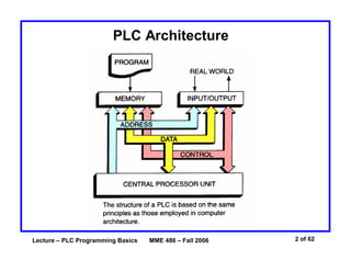
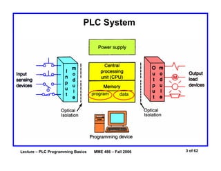
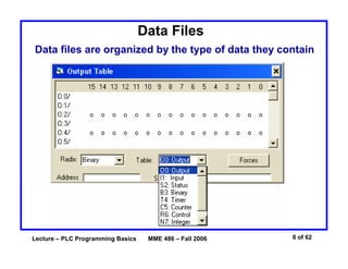
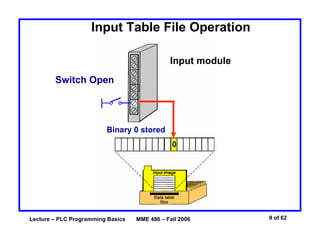
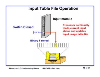
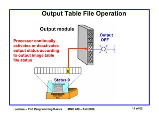
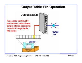
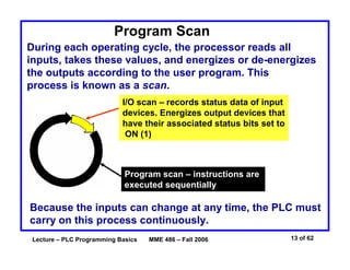
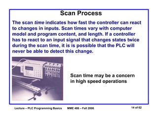
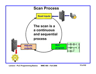
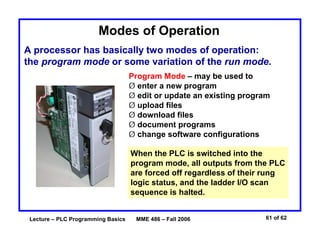
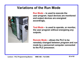
Lecture – PLC Programming Basics MME 486 – Fall 2006 1 of 62
Basics of PLC Programming
Industrial Control Systems
Fall 2006
Lecture – PLC Programming Basics MME 486 – Fall 2006 2 of 62
PLC Architecture
Lecture – PLC Programming Basics MME 486 – Fall 2006 3 of 62
PLC System
Lecture – PLC Programming Basics MME 486 – Fall 2006 4 of 62
Processor Memory Organization
Advanced ladder logic functions allow controllers to
perform calculations, make decisions and do other
complex tasks. Timers and counters are examples of
ladder logic functions. They are more complex than
basic inputs contacts and output coils and rely
heavily upon data stored in the memory of the PLC.
The memory of a PLC is organized by types.
The memory space can be divided into two broad
categories:
program and data memory.
Lecture – PLC Programming Basics MME 486 – Fall 2006 5 of 62
Memory Map
A memory map can be used to show how memory is
organized in a PLC.
Data table
User program
Housekeeping memory
§ Input/output locations
§ Internal relay and
timer/counter locations
The user program causes
the controller to operate
in a particular manner
Used to carry out
functions needed to make
the processor operate
(no access by user)
Lecture – PLC Programming Basics MME 486 – Fall 2006 6 of 62
Program Files
Program file organization
for SLC-500 controller.
The user program will
account for most of the
memory of a PLC system.
• Program files contain
the logic controlling
machine operation.
• This logic consists of
instructions that are
programmed in a
ladder logic format.
Lecture – PLC Programming Basics MME 486 – Fall 2006 7 of 62
Data Files
Data file organization
for SLC-500 controller.
The data file portion of memory
stores input and output status,
processor status, the status of
various bits and numerical data.
Lecture – PLC Programming Basics MME 486 – Fall 2006 8 of 62
Data Files
Data files are organized by the type of data they contain
Lecture – PLC Programming Basics MME 486 – Fall 2006 9 of 62
Input Table File Operation
Input module
Switch Open
Binary 0 stored
0
Lecture – PLC Programming Basics MME 486 – Fall 2006 10 of 62
Input Table File Operation
Input module
Processor continually
reads current input
status and updates
input image table file
Switch Closed
Binary 1 stored
1
Lecture – PLC Programming Basics MME 486 – Fall 2006 11 of 62
Output Table File Operation
Output module
Processor continually
activates or deactivates
output status according
to output image table
file status
Status 0
0
Output
OFF
Lecture – PLC Programming Basics MME 486 – Fall 2006 12 of 62
Output Table File Operation
Output module
Processor continually
activates or deactivates
output status according
to output image table
file status
Status 1
1
Output
ON
Lecture – PLC Programming Basics MME 486 – Fall 2006 13 of 62
Program Scan
During each operating cycle, the processor reads all
inputs, takes these values, and energizes or de-energizes
the outputs according to the user program. This
process is known as a scan.
I/O scan – records status data of input
devices. Energizes output devices that
have their associated status bits set to
ON (1)
Program scan – instructions are
executed sequentially
Because the inputs can change at any time, the PLC must
carry on this process continuously.
Lecture – PLC Programming Basics MME 486 – Fall 2006 14 of 62
Scan Process
The scan time indicates how fast the controller can react
to changes in inputs. Scan times vary with computer
model and program content, and length. If a controller
has to react to an input signal that changes states twice
during the scan time, it is is possible that the PLC will
never be able to detect this change.
Scan time may be a concern
in high speed operations
Lecture – PLC Programming Basics MME 486 – Fall 2006 15 of 62
Scan Process
Read inputs
Adjusts
outputs
Run
program
The scan is a
a continuous
and sequential
process
Lecture – PLC Programming Basics MME 486 – Fall 2006 16 of 62
Data Flow Overview
Program
Input
image
table file
Output
image
table file
Input
modules
Input
data
Examine data
Check/compare/examine
specific conditions
Output
data
Output
modules
Take some
action
Return results
Lecture – PLC Programming Basics MME 486 – Fall 2006 17 of 62
Scan Process
Input
Module
Output
Module
Program
Input
device
Output
device
Input
file
Output
file
I:3/6 O:4/7
I:3/6 O:4/7
I:3/6 O:4/7
When the input is
closed, the input
module senses a
voltage and an ON
condition (1) is
entered into the
input table bit I:3/6
During the program scan the
processor sets instructions
I:3/6 and O:4/7 to ON (1)
The processor turns
light output O:4/7
ON during the next
I/O scan
Lecture – PLC Programming Basics MME 486 – Fall 2006 18 of 62
Scan Patterns
Horizontal Scanning
Order
The processor examines
input and output
instructions from the
first command, top left
in the program,
horizontally, rung by
rung.
End of ladder
In addition to the program itself, the scan time is also dependent on
the clock frequency of the processor!
Lecture – PLC Programming Basics MME 486 – Fall 2006 19 of 62
Scan Patterns
Vertical Scanning
Order
The processor examines
input and output
instructions from the
first command, vertically,
column by column and
page by page. Pages are
executed in sequence.
End of ladder
Misunderstanding the way the PLC scans can cause programming
bugs!
Lecture – PLC Programming Basics MME 486 – Fall 2006 20 of 62
PLC Programming Languages
The term PLC programming language refers to the method
by which the user communicates information to the PLC.
The three most common
language structures are:
ladder diagram language,
Boolean language, and
functional chart.
Ladder diagram language
Boolean language
Functional
chart
Lecture – PLC Programming Basics MME 486 – Fall 2006 21 of 62
Comparing Programming Language
PB1 CR1 CR2
LS1
SOL
Relay Schematic
PB1 CR1 CR2
LS1
SOL
Equivalent ladder
diagram language
Equivalent Boolean language
Lecture – PLC Programming Basics MME 486 – Fall 2006 22 of 62
Relay-Type Instructions
The ladder diagram language is basically a
symbolic set of instructions used to create the
controller program.
These ladder instructions symbols are
arranged to obtain the desired control logic.
Lecture – PLC Programming Basics MME 486 – Fall 2006 23 of 62
Examine If Closed (XIC) Instruction
Symbol Analogous to the normally open relay
contact. For this instruction we ask
the processor to EXAMINE IF (the
contact is) CLOSED (XIC)
Typically represents any input. Can be a switch
or pushbutton, a contact from a connected output,
or a contact from an internal output.
Has a bit-level address which is examined for an
ON condition.
The status bit will be either 1 (ON) or 0 (OFF).
Lecture – PLC Programming Basics MME 486 – Fall 2006 24 of 62
Examine If Closed (XIC) Instruction
I:012
I:012
04
Lecture – PLC Programming Basics MME 486 – Fall 2006 25 of 62
Examine If Closed (XIC) Instruction
I:012
I:012
04
If the status bit is 0 (OFF), then the instruction
is FALSE.
Lecture – PLC Programming Basics MME 486 – Fall 2006 26 of 62
Examine If Closed (XIC) Instruction
I:012
I:012
04
If the status bit is 1 (ON), then the instruction is TRUE.
Lecture – PLC Programming Basics MME 486 – Fall 2006 27 of 62
Examine If Open (XIO) Instruction
Symbol Analogous to the normally closed
relay contact. For this instruction we
ask the processor to EXAMINE IF (the
contact is) OPEN (XIO).
Typically represents any input. Can be a switch or
pushbutton, a contact from a connected output,
or a contact from an internal output.
Has a bit-level address which is examined for an OFF
condition.
The status bit will be either 1 (ON) or 0 (OFF).
Lecture – PLC Programming Basics MME 486 – Fall 2006 28 of 62
Examine If Open (XIO) Instruction
I:012
I:012
04
If the status bit is 0 (OFF), then the instruction is TRUE.
Lecture – PLC Programming Basics MME 486 – Fall 2006 29 of 62
Examine If Open (XIO) Instruction
I:012
I:012
04
If the status bit is 1 (ON), then the instruction is FALSE.
Lecture – PLC Programming Basics MME 486 – Fall 2006 30 of 62
Symbol
Analogous to the relay coil. The
processor makes this instruction true
(analogous to energizing a coil) when
there is path of true XIC and XIO
instructions in the rung.
Typically represents any output that is controlled by
some combination of input logic. Can be a connected
device or an internal output (internal relay).
If any left-to-right path of input conditions is TRUE,
the output is energized (turned ON).
Output Energize (OTE) Instruction
Lecture – PLC Programming Basics MME 486 – Fall 2006 31 of 62
Output Energize (OTE) Instruction
O:013
I:012
O:013
01
I:012 I:012
11 15
OUTPUT ENERGIZE instruction - TRUE
Lecture – PLC Programming Basics MME 486 – Fall 2006 32 of 62
Output Energize (OTE) Instruction
O:013
I:012
O:013
01
I:012 I:012
11 15
OUTPUT ENERGIZE instruction - FALSE
Lecture – PLC Programming Basics MME 486 – Fall 2006 33 of 62
Status Bit Examples
A
A
A
Bit statusInput module
Output
Output
Button not actuated
True
False
ON
OFF
Lecture – PLC Programming Basics MME 486 – Fall 2006 34 of 62
Status Bit Examples
A
A
A
Bit statusInput module
Output
Output
Button actuated
OFF
ON
False
True
Lecture – PLC Programming Basics MME 486 – Fall 2006 35 of 62
A ladder rung consists of a set of input conditions,
represented by contact instructions, and an output
instruction at the end of the rung, represented by the
coil symbol.
Ladder Rung
A B C
D
Output
instruction
Input conditions
Output
instruction
Lecture – PLC Programming Basics MME 486 – Fall 2006 36 of 62
Ladder Rung
A B C
D
Output
instruction
Input conditions
Output
instruction
For an output to be activated or energized, at least one
left-to-right path of contacts most be closed. A complete
path is referred to as having logic continuity. When logic
exists the rung condition is said to be TRUE.
Lecture – PLC Programming Basics MME 486 – Fall 2006 37 of 62
Rung Continuity
Bit in memory Bit in memory
LS_1 SOL_5
1 1
The Examine If Closed instruction is TRUE
making the rung TRUE
Lecture – PLC Programming Basics MME 486 – Fall 2006 38 of 62
Rung Continuity
Bit in memory Bit in memory
LS_1 SOL_5
0 0
The Examine If Closed instruction is FALSE
making the rung False
Lecture – PLC Programming Basics MME 486 – Fall 2006 39 of 62
Allen-Bradley SLC-500 Controller Addressing
Address
input
terminal
I1:3/12
Closed input
Input image table
file 1
I:3/12
Bit address
I1:3
12
User-programmed rung
Energized
output
6
O:0:4
Address
output
terminal
O0:4/6Output image table
file 0
O:0:4/6
Bit address
Lecture – PLC Programming Basics MME 486 – Fall 2006 40 of 62
Structure of A 16-Bit Word
15 14 13 12 11 10 9 8 7 6 5 4 3 2 1 0
Word
(16 bits)
Bit
0
OFF ON
1
I/O Connection Diagram
L1 L2
PB1
LS1
I:4/5
I:4/6
L1 L2
O:2/3
O:3/6
SOL 1
PL 1
R
Lecture – PLC Programming Basics MME 486 – Fall 2006 41 of 62
Parallel Input Branch Instructions
A
B
C Branch instructions are used
to create parallel paths of
input condition instructions.
If at least one of these parallel
branches forms a true logic
path, the logic is enabled.
Lecture – PLC Programming Basics MME 486 – Fall 2006 42 of 62
Parallel Output Branching
A
B
C
D
E
On most PLC models, branches can be established at
both the input and output portion of the rung.
With output branching, you can program parallel outputs
on a rung to allow a true logic path to control multiple
outputs.
Lecture – PLC Programming Basics MME 486 – Fall 2006 43 of 62
Nested Input and Output Branches
Input and output branches can be nested to avoid
redundant instructions and to speed up the processor
scan time.
A nested branch starts or ends within another branch.
Lecture – PLC Programming Basics MME 486 – Fall 2006 44 of 62
Nested Contact Program
A B C
D
E
Y
Nested
contact
On some PLC models,
the programming of a
nested branch circuit
cannot be done directly.
Contact
instruction
C repeated
A B C
CD
E
Y
Reprogrammed to
obtain the required
logic.
Lecture – PLC Programming Basics MME 486 – Fall 2006 45 of 62
PLC Matrix Limitation Diagram
Max parallel
lines
No. outputs
per rung and
location of the
output in the rung
Max series
contacts
There may be limitations to the number of series contacts
instructions, number of parallel lines, and the number of outputs and
their location on the rung.
Lecture – PLC Programming Basics MME 486 – Fall 2006 46 of 62
Programming of Vertical Contacts
A
B
C
D
E
Y
Original program
Y = (AD) + (BCD) + (BE) + (ACE)
A D
B
B
A
C
C
D
E
E
Y
Reprogrammed to obtain the
required logic
Lecture – PLC Programming Basics MME 486 – Fall 2006 47 of 62
Programming for Different Scan Patterns
C
Original program
Y = (ABC) + (ADE) + (FE) + (FDBC)
A
D
B
E
F
Y
A B
D E
Y
F
A
C
CB
Reprogrammed to obtain the
required logicE
F D
Lecture – PLC Programming Basics MME 486 – Fall 2006 48 of 62
Internal Control Relay
The internal output operates just as any other output
that is controlled by programmed logic; however, the
output is used strictly for internal purposes.
The internal output does not directly control an
output device.
The advantage of using internal outputs is that there
are many situations where an output instruction is
required in a program, but no physical connection to
a field device is needed. Their use in this type of
instance can minimize output card requirements.
Lecture – PLC Programming Basics MME 486 – Fall 2006 49 of 62
Extending the Number of Series Contacts Using
an Internal Control Relay
Internal
relay coil
Rung 1
Rung 2
Internal
relay
contact
Discrete output (requires
one physical connection
on the output module)
Lecture – PLC Programming Basics MME 486 – Fall 2006 50 of 62
PB1 PB2
User program
providing the
same results
PL
Note that both pushbuttons are represented by the XIC symbol. This
is because the normal state of an input (NO or NC) does not matter!
What does matter is that if contacts need to close to energize the
output, then the XIC instruction is used. Since both PB1 and PB2
must close to energize the PL, the XIC instruction is used for both.
Programming The XIC Instruction
Hardwired Circuit
PB1 PB2
PL
Lecture – PLC Programming Basics MME 486 – Fall 2006 51 of 62
When the pushbutton is open in the hardwired circuit, relay coil CR is de-
energized and contacts CR1 close to switch the PL on. When the
pushbutton is closed, relay coil CR is energized and contacts CR1 open
to switch the PL off. The pushbutton is represented in the user program
by an XIO instruction. This is because the rung must be true when the
external pushbutton is open, and false when the pushbutton is closed.
Programming The XIO Instruction
PB1
CR
CR1
PL
Hardwired Circuit
User program providing
the same results
PB1
PL
Lecture – PLC Programming Basics MME 486 – Fall 2006 52 of 62
Operation of The XIC and XIO Instructions
Logic 0 False FalseTrue
Logic 1 True TrueFalse
If the data
table bit is:
The status of the instruction is:
XIC
Examine If Closed
XIO
Examine If Open
OTE
Output Energize
Summary of status conditions
Lecture – PLC Programming Basics MME 486 – Fall 2006 53 of 62
Operation of The XIC and XIO Instructions
State of the output as determined by the changing
state of the inputs in the rung
t1 (initial) False FalseTrue 0 0 0
t2
t3
t4
True True Goes true 1 0 1
True False Goes false 1 1 0
False False Remains false 0 1 0
Time
Inputs Output Bit status
XIC
XIC XIC
XIO
XIO XIO
OTE
OTE OTE
Input instructions Output instruction
Lecture – PLC Programming Basics MME 486 – Fall 2006 54 of 62
Entering the Ladder Diagram
A personal computer is most often used to enter the
ladder diagram.
The computer is adapted
to the particular PLC
model using the relevant
programmable controller
software.
Lecture – PLC Programming Basics MME 486 – Fall 2006 55 of 62
RSLogix Main Screen
Different screens, toolbars and windows dialog boxes are
used to navigate through the Windows environment
Lecture – PLC Programming Basics MME 486 – Fall 2006 56 of 62
Bit Instructions Tool Bar
To place an instruction on a rung, click its icon
on the toolbar and simply drag the instruction
straight off the toolbar onto the rung of the
ladder.
Lecture – PLC Programming Basics MME 486 – Fall 2006 57 of 62
Select Processor Type Screen
The programming software needs to know what
processor is being used in conjunction with the program.
You simply
scroll down
the list until
you find the
processor you
are using and
select it.
1747-L40E
Lecture – PLC Programming Basics MME 486 – Fall 2006 58 of 62
I/O Configuration Screen
The I/O screen
lets you click or
drag-and-drop a
module from an
all inclusive list to
assign it to a slot
in your
configuration.
Lecture – PLC Programming Basics MME 486 – Fall 2006 59 of 62
Data File Screen
Data file screens
contain data that
is used in
conjunction with
ladder program
instructions. These
include:
Input
Output
Timer
Counter
Integer
Bit
Lecture – PLC Programming Basics MME 486 – Fall 2006 60 of 62
Monitoring a Ladder Logic Program
Operation of the logic is apparent from the highlighting
of rungs of the various instructions on screen, which
identifies the logic state in real time and has logic
continuity.
Highlighted rungs indicate the instruction is true
Lecture – PLC Programming Basics MME 486 – Fall 2006 61 of 62
Modes of Operation
A processor has basically two modes of operation:
the program mode or some variation of the run mode.
Program Mode – may be used to
Ø enter a new program
Ø edit or update an existing program
Ø upload files
Ø download files
Ø document programs
Ø change software configurations
When the PLC is switched into the
program mode, all outputs from the PLC
are forced off regardless of their rung
logic status, and the ladder I/O scan
sequence is halted.
Lecture – PLC Programming Basics MME 486 – Fall 2006 62 of 62
Variations of the Run Mode
Run Mode – is used to execute the
user program. Input devices are monitored
and output devices are energized
accordingly.
Test Mode – is used to operate, or monitor,
the user program without energizing any
outputs.
Remote Mode – allows the PLC to be
remotely changed between program and run
mode by a personnel computer connected
to the PLC processor.

Basics of plc_programming

  • 1.
    Lecture – PLCProgramming Basics MME 486 – Fall 2006 1 of 62 Basics of PLC Programming Industrial Control Systems Fall 2006
  • 2.
    Lecture – PLCProgramming Basics MME 486 – Fall 2006 2 of 62 PLC Architecture
  • 3.
    Lecture – PLCProgramming Basics MME 486 – Fall 2006 3 of 62 PLC System
  • 4.
    Lecture – PLCProgramming Basics MME 486 – Fall 2006 4 of 62 Processor Memory Organization Advanced ladder logic functions allow controllers to perform calculations, make decisions and do other complex tasks. Timers and counters are examples of ladder logic functions. They are more complex than basic inputs contacts and output coils and rely heavily upon data stored in the memory of the PLC. The memory of a PLC is organized by types. The memory space can be divided into two broad categories: program and data memory.
  • 5.
    Lecture – PLCProgramming Basics MME 486 – Fall 2006 5 of 62 Memory Map A memory map can be used to show how memory is organized in a PLC. Data table User program Housekeeping memory § Input/output locations § Internal relay and timer/counter locations The user program causes the controller to operate in a particular manner Used to carry out functions needed to make the processor operate (no access by user)
  • 6.
    Lecture – PLCProgramming Basics MME 486 – Fall 2006 6 of 62 Program Files Program file organization for SLC-500 controller. The user program will account for most of the memory of a PLC system. • Program files contain the logic controlling machine operation. • This logic consists of instructions that are programmed in a ladder logic format.
  • 7.
    Lecture – PLCProgramming Basics MME 486 – Fall 2006 7 of 62 Data Files Data file organization for SLC-500 controller. The data file portion of memory stores input and output status, processor status, the status of various bits and numerical data.
  • 8.
    Lecture – PLCProgramming Basics MME 486 – Fall 2006 8 of 62 Data Files Data files are organized by the type of data they contain
  • 9.
    Lecture – PLCProgramming Basics MME 486 – Fall 2006 9 of 62 Input Table File Operation Input module Switch Open Binary 0 stored 0
  • 10.
    Lecture – PLCProgramming Basics MME 486 – Fall 2006 10 of 62 Input Table File Operation Input module Processor continually reads current input status and updates input image table file Switch Closed Binary 1 stored 1
  • 11.
    Lecture – PLCProgramming Basics MME 486 – Fall 2006 11 of 62 Output Table File Operation Output module Processor continually activates or deactivates output status according to output image table file status Status 0 0 Output OFF
  • 12.
    Lecture – PLCProgramming Basics MME 486 – Fall 2006 12 of 62 Output Table File Operation Output module Processor continually activates or deactivates output status according to output image table file status Status 1 1 Output ON
  • 13.
    Lecture – PLCProgramming Basics MME 486 – Fall 2006 13 of 62 Program Scan During each operating cycle, the processor reads all inputs, takes these values, and energizes or de-energizes the outputs according to the user program. This process is known as a scan. I/O scan – records status data of input devices. Energizes output devices that have their associated status bits set to ON (1) Program scan – instructions are executed sequentially Because the inputs can change at any time, the PLC must carry on this process continuously.
  • 14.
    Lecture – PLCProgramming Basics MME 486 – Fall 2006 14 of 62 Scan Process The scan time indicates how fast the controller can react to changes in inputs. Scan times vary with computer model and program content, and length. If a controller has to react to an input signal that changes states twice during the scan time, it is is possible that the PLC will never be able to detect this change. Scan time may be a concern in high speed operations
  • 15.
    Lecture – PLCProgramming Basics MME 486 – Fall 2006 15 of 62 Scan Process Read inputs Adjusts outputs Run program The scan is a a continuous and sequential process
  • 16.
    Lecture – PLCProgramming Basics MME 486 – Fall 2006 16 of 62 Data Flow Overview Program Input image table file Output image table file Input modules Input data Examine data Check/compare/examine specific conditions Output data Output modules Take some action Return results
  • 17.
    Lecture – PLCProgramming Basics MME 486 – Fall 2006 17 of 62 Scan Process Input Module Output Module Program Input device Output device Input file Output file I:3/6 O:4/7 I:3/6 O:4/7 I:3/6 O:4/7 When the input is closed, the input module senses a voltage and an ON condition (1) is entered into the input table bit I:3/6 During the program scan the processor sets instructions I:3/6 and O:4/7 to ON (1) The processor turns light output O:4/7 ON during the next I/O scan
  • 18.
    Lecture – PLCProgramming Basics MME 486 – Fall 2006 18 of 62 Scan Patterns Horizontal Scanning Order The processor examines input and output instructions from the first command, top left in the program, horizontally, rung by rung. End of ladder In addition to the program itself, the scan time is also dependent on the clock frequency of the processor!
  • 19.
    Lecture – PLCProgramming Basics MME 486 – Fall 2006 19 of 62 Scan Patterns Vertical Scanning Order The processor examines input and output instructions from the first command, vertically, column by column and page by page. Pages are executed in sequence. End of ladder Misunderstanding the way the PLC scans can cause programming bugs!
  • 20.
    Lecture – PLCProgramming Basics MME 486 – Fall 2006 20 of 62 PLC Programming Languages The term PLC programming language refers to the method by which the user communicates information to the PLC. The three most common language structures are: ladder diagram language, Boolean language, and functional chart. Ladder diagram language Boolean language Functional chart
  • 21.
    Lecture – PLCProgramming Basics MME 486 – Fall 2006 21 of 62 Comparing Programming Language PB1 CR1 CR2 LS1 SOL Relay Schematic PB1 CR1 CR2 LS1 SOL Equivalent ladder diagram language Equivalent Boolean language
  • 22.
    Lecture – PLCProgramming Basics MME 486 – Fall 2006 22 of 62 Relay-Type Instructions The ladder diagram language is basically a symbolic set of instructions used to create the controller program. These ladder instructions symbols are arranged to obtain the desired control logic.
  • 23.
    Lecture – PLCProgramming Basics MME 486 – Fall 2006 23 of 62 Examine If Closed (XIC) Instruction Symbol Analogous to the normally open relay contact. For this instruction we ask the processor to EXAMINE IF (the contact is) CLOSED (XIC) Typically represents any input. Can be a switch or pushbutton, a contact from a connected output, or a contact from an internal output. Has a bit-level address which is examined for an ON condition. The status bit will be either 1 (ON) or 0 (OFF).
  • 24.
    Lecture – PLCProgramming Basics MME 486 – Fall 2006 24 of 62 Examine If Closed (XIC) Instruction I:012 I:012 04
  • 25.
    Lecture – PLCProgramming Basics MME 486 – Fall 2006 25 of 62 Examine If Closed (XIC) Instruction I:012 I:012 04 If the status bit is 0 (OFF), then the instruction is FALSE.
  • 26.
    Lecture – PLCProgramming Basics MME 486 – Fall 2006 26 of 62 Examine If Closed (XIC) Instruction I:012 I:012 04 If the status bit is 1 (ON), then the instruction is TRUE.
  • 27.
    Lecture – PLCProgramming Basics MME 486 – Fall 2006 27 of 62 Examine If Open (XIO) Instruction Symbol Analogous to the normally closed relay contact. For this instruction we ask the processor to EXAMINE IF (the contact is) OPEN (XIO). Typically represents any input. Can be a switch or pushbutton, a contact from a connected output, or a contact from an internal output. Has a bit-level address which is examined for an OFF condition. The status bit will be either 1 (ON) or 0 (OFF).
  • 28.
    Lecture – PLCProgramming Basics MME 486 – Fall 2006 28 of 62 Examine If Open (XIO) Instruction I:012 I:012 04 If the status bit is 0 (OFF), then the instruction is TRUE.
  • 29.
    Lecture – PLCProgramming Basics MME 486 – Fall 2006 29 of 62 Examine If Open (XIO) Instruction I:012 I:012 04 If the status bit is 1 (ON), then the instruction is FALSE.
  • 30.
    Lecture – PLCProgramming Basics MME 486 – Fall 2006 30 of 62 Symbol Analogous to the relay coil. The processor makes this instruction true (analogous to energizing a coil) when there is path of true XIC and XIO instructions in the rung. Typically represents any output that is controlled by some combination of input logic. Can be a connected device or an internal output (internal relay). If any left-to-right path of input conditions is TRUE, the output is energized (turned ON). Output Energize (OTE) Instruction
  • 31.
    Lecture – PLCProgramming Basics MME 486 – Fall 2006 31 of 62 Output Energize (OTE) Instruction O:013 I:012 O:013 01 I:012 I:012 11 15 OUTPUT ENERGIZE instruction - TRUE
  • 32.
    Lecture – PLCProgramming Basics MME 486 – Fall 2006 32 of 62 Output Energize (OTE) Instruction O:013 I:012 O:013 01 I:012 I:012 11 15 OUTPUT ENERGIZE instruction - FALSE
  • 33.
    Lecture – PLCProgramming Basics MME 486 – Fall 2006 33 of 62 Status Bit Examples A A A Bit statusInput module Output Output Button not actuated True False ON OFF
  • 34.
    Lecture – PLCProgramming Basics MME 486 – Fall 2006 34 of 62 Status Bit Examples A A A Bit statusInput module Output Output Button actuated OFF ON False True
  • 35.
    Lecture – PLCProgramming Basics MME 486 – Fall 2006 35 of 62 A ladder rung consists of a set of input conditions, represented by contact instructions, and an output instruction at the end of the rung, represented by the coil symbol. Ladder Rung A B C D Output instruction Input conditions Output instruction
  • 36.
    Lecture – PLCProgramming Basics MME 486 – Fall 2006 36 of 62 Ladder Rung A B C D Output instruction Input conditions Output instruction For an output to be activated or energized, at least one left-to-right path of contacts most be closed. A complete path is referred to as having logic continuity. When logic exists the rung condition is said to be TRUE.
  • 37.
    Lecture – PLCProgramming Basics MME 486 – Fall 2006 37 of 62 Rung Continuity Bit in memory Bit in memory LS_1 SOL_5 1 1 The Examine If Closed instruction is TRUE making the rung TRUE
  • 38.
    Lecture – PLCProgramming Basics MME 486 – Fall 2006 38 of 62 Rung Continuity Bit in memory Bit in memory LS_1 SOL_5 0 0 The Examine If Closed instruction is FALSE making the rung False
  • 39.
    Lecture – PLCProgramming Basics MME 486 – Fall 2006 39 of 62 Allen-Bradley SLC-500 Controller Addressing Address input terminal I1:3/12 Closed input Input image table file 1 I:3/12 Bit address I1:3 12 User-programmed rung Energized output 6 O:0:4 Address output terminal O0:4/6Output image table file 0 O:0:4/6 Bit address
  • 40.
    Lecture – PLCProgramming Basics MME 486 – Fall 2006 40 of 62 Structure of A 16-Bit Word 15 14 13 12 11 10 9 8 7 6 5 4 3 2 1 0 Word (16 bits) Bit 0 OFF ON 1 I/O Connection Diagram L1 L2 PB1 LS1 I:4/5 I:4/6 L1 L2 O:2/3 O:3/6 SOL 1 PL 1 R
  • 41.
    Lecture – PLCProgramming Basics MME 486 – Fall 2006 41 of 62 Parallel Input Branch Instructions A B C Branch instructions are used to create parallel paths of input condition instructions. If at least one of these parallel branches forms a true logic path, the logic is enabled.
  • 42.
    Lecture – PLCProgramming Basics MME 486 – Fall 2006 42 of 62 Parallel Output Branching A B C D E On most PLC models, branches can be established at both the input and output portion of the rung. With output branching, you can program parallel outputs on a rung to allow a true logic path to control multiple outputs.
  • 43.
    Lecture – PLCProgramming Basics MME 486 – Fall 2006 43 of 62 Nested Input and Output Branches Input and output branches can be nested to avoid redundant instructions and to speed up the processor scan time. A nested branch starts or ends within another branch.
  • 44.
    Lecture – PLCProgramming Basics MME 486 – Fall 2006 44 of 62 Nested Contact Program A B C D E Y Nested contact On some PLC models, the programming of a nested branch circuit cannot be done directly. Contact instruction C repeated A B C CD E Y Reprogrammed to obtain the required logic.
  • 45.
    Lecture – PLCProgramming Basics MME 486 – Fall 2006 45 of 62 PLC Matrix Limitation Diagram Max parallel lines No. outputs per rung and location of the output in the rung Max series contacts There may be limitations to the number of series contacts instructions, number of parallel lines, and the number of outputs and their location on the rung.
  • 46.
    Lecture – PLCProgramming Basics MME 486 – Fall 2006 46 of 62 Programming of Vertical Contacts A B C D E Y Original program Y = (AD) + (BCD) + (BE) + (ACE) A D B B A C C D E E Y Reprogrammed to obtain the required logic
  • 47.
    Lecture – PLCProgramming Basics MME 486 – Fall 2006 47 of 62 Programming for Different Scan Patterns C Original program Y = (ABC) + (ADE) + (FE) + (FDBC) A D B E F Y A B D E Y F A C CB Reprogrammed to obtain the required logicE F D
  • 48.
    Lecture – PLCProgramming Basics MME 486 – Fall 2006 48 of 62 Internal Control Relay The internal output operates just as any other output that is controlled by programmed logic; however, the output is used strictly for internal purposes. The internal output does not directly control an output device. The advantage of using internal outputs is that there are many situations where an output instruction is required in a program, but no physical connection to a field device is needed. Their use in this type of instance can minimize output card requirements.
  • 49.
    Lecture – PLCProgramming Basics MME 486 – Fall 2006 49 of 62 Extending the Number of Series Contacts Using an Internal Control Relay Internal relay coil Rung 1 Rung 2 Internal relay contact Discrete output (requires one physical connection on the output module)
  • 50.
    Lecture – PLCProgramming Basics MME 486 – Fall 2006 50 of 62 PB1 PB2 User program providing the same results PL Note that both pushbuttons are represented by the XIC symbol. This is because the normal state of an input (NO or NC) does not matter! What does matter is that if contacts need to close to energize the output, then the XIC instruction is used. Since both PB1 and PB2 must close to energize the PL, the XIC instruction is used for both. Programming The XIC Instruction Hardwired Circuit PB1 PB2 PL
  • 51.
    Lecture – PLCProgramming Basics MME 486 – Fall 2006 51 of 62 When the pushbutton is open in the hardwired circuit, relay coil CR is de- energized and contacts CR1 close to switch the PL on. When the pushbutton is closed, relay coil CR is energized and contacts CR1 open to switch the PL off. The pushbutton is represented in the user program by an XIO instruction. This is because the rung must be true when the external pushbutton is open, and false when the pushbutton is closed. Programming The XIO Instruction PB1 CR CR1 PL Hardwired Circuit User program providing the same results PB1 PL
  • 52.
    Lecture – PLCProgramming Basics MME 486 – Fall 2006 52 of 62 Operation of The XIC and XIO Instructions Logic 0 False FalseTrue Logic 1 True TrueFalse If the data table bit is: The status of the instruction is: XIC Examine If Closed XIO Examine If Open OTE Output Energize Summary of status conditions
  • 53.
    Lecture – PLCProgramming Basics MME 486 – Fall 2006 53 of 62 Operation of The XIC and XIO Instructions State of the output as determined by the changing state of the inputs in the rung t1 (initial) False FalseTrue 0 0 0 t2 t3 t4 True True Goes true 1 0 1 True False Goes false 1 1 0 False False Remains false 0 1 0 Time Inputs Output Bit status XIC XIC XIC XIO XIO XIO OTE OTE OTE Input instructions Output instruction
  • 54.
    Lecture – PLCProgramming Basics MME 486 – Fall 2006 54 of 62 Entering the Ladder Diagram A personal computer is most often used to enter the ladder diagram. The computer is adapted to the particular PLC model using the relevant programmable controller software.
  • 55.
    Lecture – PLCProgramming Basics MME 486 – Fall 2006 55 of 62 RSLogix Main Screen Different screens, toolbars and windows dialog boxes are used to navigate through the Windows environment
  • 56.
    Lecture – PLCProgramming Basics MME 486 – Fall 2006 56 of 62 Bit Instructions Tool Bar To place an instruction on a rung, click its icon on the toolbar and simply drag the instruction straight off the toolbar onto the rung of the ladder.
  • 57.
    Lecture – PLCProgramming Basics MME 486 – Fall 2006 57 of 62 Select Processor Type Screen The programming software needs to know what processor is being used in conjunction with the program. You simply scroll down the list until you find the processor you are using and select it. 1747-L40E
  • 58.
    Lecture – PLCProgramming Basics MME 486 – Fall 2006 58 of 62 I/O Configuration Screen The I/O screen lets you click or drag-and-drop a module from an all inclusive list to assign it to a slot in your configuration.
  • 59.
    Lecture – PLCProgramming Basics MME 486 – Fall 2006 59 of 62 Data File Screen Data file screens contain data that is used in conjunction with ladder program instructions. These include: Input Output Timer Counter Integer Bit
  • 60.
    Lecture – PLCProgramming Basics MME 486 – Fall 2006 60 of 62 Monitoring a Ladder Logic Program Operation of the logic is apparent from the highlighting of rungs of the various instructions on screen, which identifies the logic state in real time and has logic continuity. Highlighted rungs indicate the instruction is true
  • 61.
    Lecture – PLCProgramming Basics MME 486 – Fall 2006 61 of 62 Modes of Operation A processor has basically two modes of operation: the program mode or some variation of the run mode. Program Mode – may be used to Ø enter a new program Ø edit or update an existing program Ø upload files Ø download files Ø document programs Ø change software configurations When the PLC is switched into the program mode, all outputs from the PLC are forced off regardless of their rung logic status, and the ladder I/O scan sequence is halted.
  • 62.
    Lecture – PLCProgramming Basics MME 486 – Fall 2006 62 of 62 Variations of the Run Mode Run Mode – is used to execute the user program. Input devices are monitored and output devices are energized accordingly. Test Mode – is used to operate, or monitor, the user program without energizing any outputs. Remote Mode – allows the PLC to be remotely changed between program and run mode by a personnel computer connected to the PLC processor.