Downloaded 3,770 times
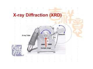

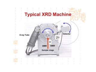
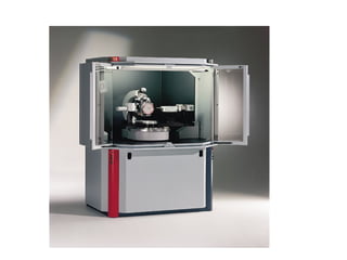
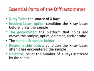
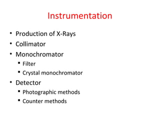
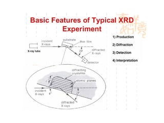
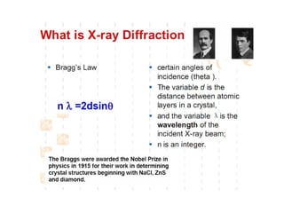
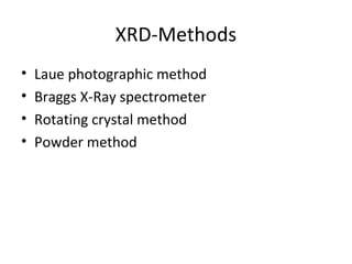
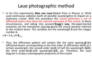
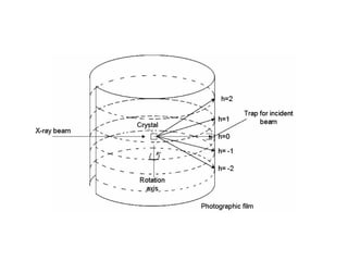
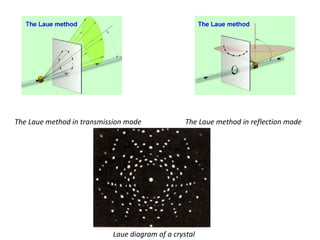
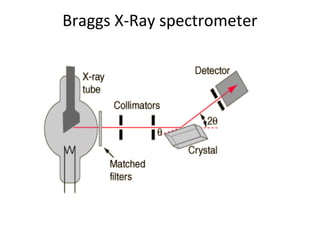
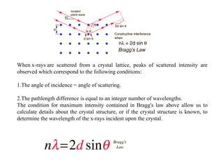


The document discusses the key components and functioning of a diffractometer used in X-ray crystallography. It describes the X-ray tube, optics, goniometer, sample holder, detector and how they are used to produce and analyze diffracted X-rays. It also explains Bragg's law which governs X-ray diffraction from crystal planes and is important for analyzing diffraction patterns. Different X-ray diffraction methods including Laue, rotating crystal and powder methods are also summarized.


![Xrd presentation [autosaved] [autosaved] copy (2)](https://cdn.slidesharecdn.com/ss_thumbnails/xrdpresentationautosavedautosaved-copy2-190813130515-thumbnail.jpg?width=640&height=640&fit=bounds)


