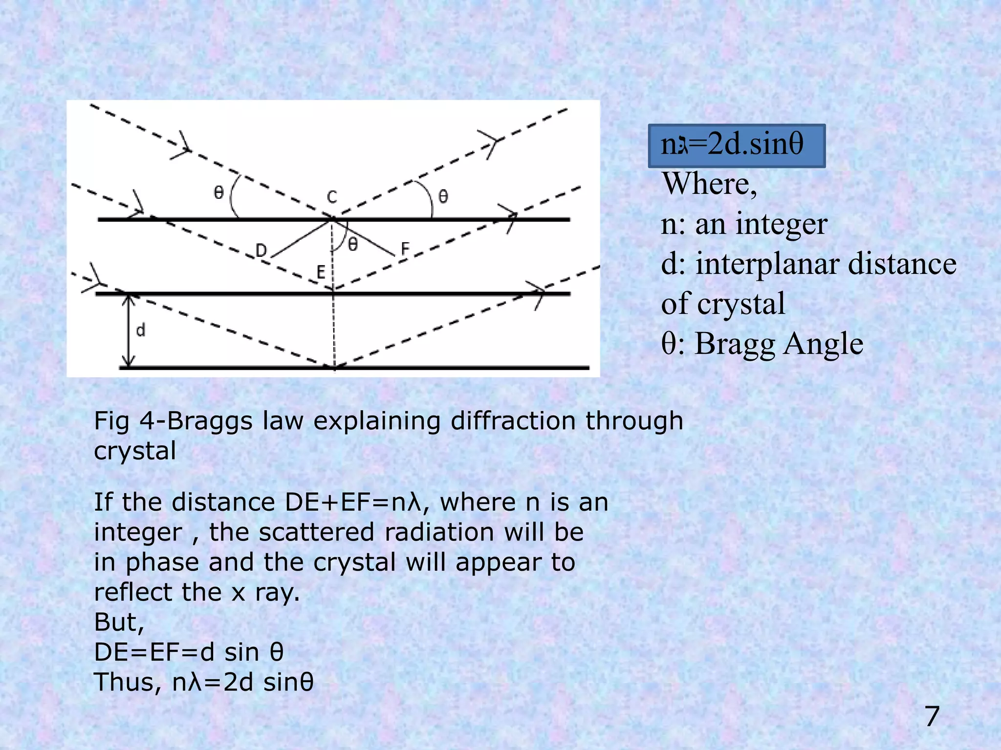
X-Ray Diffraction (XRD)
IN PHARMACEUTICAL
Industry
Presented by :
SWASTIK JYOTI PAL
Roll no-19320318001
M.Pharm 1st yr(2018-20)
Bengal School of Technology
Hooghly,West Bengal1
“X-Rays”
• X-rays were discovered in 1895 by German Scientist
William Röntgen.
• X-RAYS are part of electromagnetic spectrum with
wavelength shorter than visible light.
• Most X-Rays have wavelength ranging from 0.01 to 10
nm.
2
Fig 1-position of x ray in electromagnetic spectrum
X-ray Crystallography
 A tool used for identifying the atomic and molecular structure
of a crystal, in which the crystalline atoms cause a beam of
incident X-rays to diffract into many specific directions.
 Measuring the angles and intensities of these diffracted
beams, a crystallographer can produce a three-dimensional
picture of the density of electrons within the crystal.
 From this electron density, the mean positions of the atoms in
the crystal can be determined, as well as their chemical bonds,
their disorder and various other information.
 Why only x-ray are used? Because x-rays have wavelengths of
about the same magnitude as the distance between the atoms or
molecules of crystal.
4
Crystals and Lattice
A. Crystallography involves the general consideration of how
crystals can be built from small units.
B. This corresponds to the infinite repetition of identical
structural units (frequently referred to as a unit cell) in space.
C. In other words, the structure of all crystals can be described
by a lattice, with a group of atoms allocated to every lattice
point.
D. Based on edge length and axial angle there are 14 Bravis
lattice .
4
Fig 2- a unit
cell
How are diffraction patterns made?
When X-rays are
scattered from a
crystalline solid they
can constructively
interfere , producing a
diffracted beam.
5
Fig 3-constructive vs destructive
interference
Bragg’s Diffraction
• Diffraction from a three dimensional periodic structure such
as atoms in a crystal is called Bragg Diffraction.
• Consequence of interference between waves reflecting
from different crystal planes.
• Constructive interference is given by Bragg's law:
• Where λ is the wavelength, d is the distance between crystal
planes, θ is the angle of the diffracted wave. and n is an
integer known as the order of the diffracted beam.
nλ = 2d sin θ
6
n‫2=גּ‬d.sinθ
Where,
n: an integer
d: interplanar distance
of crystal
θ: Bragg Angle
7
If the distance DE+EF=nλ, where n is an
integer , the scattered radiation will be
in phase and the crystal will appear to
reflect the x ray.
But,
DE=EF=d sin θ
Thus, nλ=2d sinθ
Fig 4-Braggs law explaining diffraction through
crystal
X-ray Generation
At the level of electrons-
1. Expulsion of electrons
from one of the lower
quantum
2. Vacancy filled by an
electron from upper
shell.
3. Emission of photon.
8
X rays are produced
whenever high speed
electrons collide with a
metal target .
A source of electrons – hot
Tungsten filament,a high
accelerating voltage
between the cathode(W)
and the anode and a metal
target (Cu,Al,Mo,Mg).
The anode is water cooled
block of Cu containing
desired target metal
9
Fig 5-schematic diagram of an
X ray tube
Fig 6- X ray generation
at electronic level
Diffraction Methods
10
X ray diffraction
methods
Laue method
Transmission
method
Back reflection
method
Rotating crystal
method
Powder method
11
Fig 7-A typical working diagram of a
X-ray diffractometer
APPLICATIONS IN
PHARMACEUTICAL
INDUSTRY:
12
1.DRUG DEVELOPMENT:
• XRD provides details on degree of crystallinity and
amorphous content of synthetic mixtures.
• Crystalline impurities present can be quantified
down to 0.05% levels.
• XRD data is accepted for new product registrations
and patent applications.
• Single crystal structure of the active ingredient
and powder pattern of the finished formulation are
essential prerequisites for registration of new
patents.
13
2.CRYSTAL STRUCTURE ANALYSIS– the lattice
type and dimensions of a unit cell need to be
specified for the crystalline content.
Diffraction patterns: When you shine a light beam
through a crystal, you get a distinctive pattern of
bright spots called a diffraction pattern. This pattern
is actually three dimensional.
Information from a diffraction pattern-
• Phase Identification
• Crystal Size
• Crystal Quality
• Texture (to some extent)
• Crystal Structure
14
15
• Peak positions determined by size and shape of unit cell
• Peak intensities determined by the atomic number and
position of the various atoms within the unit cell
• Peak widths determined by instrument parameters ,
temperature, and crystal size, strain, and imperfections
Fig 8- XRD
graphs
16
3.POLYMORPHISM -polymorphic content can impact
properties such as solubility and dissolution rate,
bioavailability and stability so it is important to collect
details on polymorphic properties of ingredients of a
drug material
Fig 9-XRD
patterns of (a)
crystalline and
(b) amorphous
sucrose
17
4.PERCENTAGE OF CRYSTALLINITY– the
percent crystallinity is a valuable parameter for
drug dosage form. It has significant influence
on manufacturing and processing as well as the
pharmacological behaviour.
5. COMPATIBILITY WITH EXCIPIENTS-
makes it an ideal choice for studies on active
drug- excipient combinations. A detailed study
of the chosen excipients with active
pharmaceutical ingredient is a must for
consistency of properties such as drug release
and bio- availability.
6. MANUFACTURING PROCESS CONTROL-
Manufacturing process can involve morphological changes in
crystalline phase due to introduction of stress forces. Such
changes can influence a drug’s bioavailability
The nondestructive nature of XRD analysis makes it an ideal
choice to fix the safe tableting pressure range so that the
dosage form achieves its targeted dissolution rate and bio
availability.
7. IDENTIFICATION OF IMPURITIES-
X-ray diffraction pattern of any specimens match with standard
Presence of Additional lines on the photograph of specimen,
indicate the presence of impurity.
e.g In cosmetic talc, the contaminant tremolite (a potentially
carcinogen ) can be detected by x-ray diffraction technique.
18
CONCLUSION
X-ray Diffraction is a very useful to characterize materials as it is:
1. A non destructive and easy method
2. X rays are not much absorbed by air,so the specimen need not to
be in an evacuated chamber .
3. This method is less expensive than other instrumental analysis
methods.
4. Requires minimal sample preparations.
5. Applicable over a wide range of samples.
6. Spectra obtained are simple and easy to interpret.
19
1.Waseda Y,Matsubara E,Shinoda K. X-Ray Diffraction
Crystallography-Introduction, Examples and Solved Problems.
London, New York:Springer ; 2011 ;p.– 1-5,21-25.
2.Hammond C. The basics of crystallography and diffraction.
Third edition . New York : Oxford University Press ; 2011 ;p. 210-
215.
3.Ladd M,Palmer R . Structure determination - x ray
crystallography . Fifth edition . New York, London:Springer ;
2013 ; p.190-220.
4.Skoog D,Holler F,Crouch S. Principles of instrumental analysis.
Sixth edition. Australia:Thomson publication ;2007;p. 309-310.
REFERENCE
20
21
THANK
YOU!!!

X ray diffraction

  • 1.
    X-Ray Diffraction (XRD) INPHARMACEUTICAL Industry Presented by : SWASTIK JYOTI PAL Roll no-19320318001 M.Pharm 1st yr(2018-20) Bengal School of Technology Hooghly,West Bengal1
  • 2.
    “X-Rays” • X-rays werediscovered in 1895 by German Scientist William Röntgen. • X-RAYS are part of electromagnetic spectrum with wavelength shorter than visible light. • Most X-Rays have wavelength ranging from 0.01 to 10 nm. 2 Fig 1-position of x ray in electromagnetic spectrum
  • 3.
    X-ray Crystallography  Atool used for identifying the atomic and molecular structure of a crystal, in which the crystalline atoms cause a beam of incident X-rays to diffract into many specific directions.  Measuring the angles and intensities of these diffracted beams, a crystallographer can produce a three-dimensional picture of the density of electrons within the crystal.  From this electron density, the mean positions of the atoms in the crystal can be determined, as well as their chemical bonds, their disorder and various other information.  Why only x-ray are used? Because x-rays have wavelengths of about the same magnitude as the distance between the atoms or molecules of crystal. 4
  • 4.
    Crystals and Lattice A.Crystallography involves the general consideration of how crystals can be built from small units. B. This corresponds to the infinite repetition of identical structural units (frequently referred to as a unit cell) in space. C. In other words, the structure of all crystals can be described by a lattice, with a group of atoms allocated to every lattice point. D. Based on edge length and axial angle there are 14 Bravis lattice . 4 Fig 2- a unit cell
  • 5.
    How are diffractionpatterns made? When X-rays are scattered from a crystalline solid they can constructively interfere , producing a diffracted beam. 5 Fig 3-constructive vs destructive interference
  • 6.
    Bragg’s Diffraction • Diffractionfrom a three dimensional periodic structure such as atoms in a crystal is called Bragg Diffraction. • Consequence of interference between waves reflecting from different crystal planes. • Constructive interference is given by Bragg's law: • Where λ is the wavelength, d is the distance between crystal planes, θ is the angle of the diffracted wave. and n is an integer known as the order of the diffracted beam. nλ = 2d sin θ 6
  • 7.
    n‫2=גּ‬d.sinθ Where, n: an integer d:interplanar distance of crystal θ: Bragg Angle 7 If the distance DE+EF=nλ, where n is an integer , the scattered radiation will be in phase and the crystal will appear to reflect the x ray. But, DE=EF=d sin θ Thus, nλ=2d sinθ Fig 4-Braggs law explaining diffraction through crystal
  • 8.
    X-ray Generation At thelevel of electrons- 1. Expulsion of electrons from one of the lower quantum 2. Vacancy filled by an electron from upper shell. 3. Emission of photon. 8 X rays are produced whenever high speed electrons collide with a metal target . A source of electrons – hot Tungsten filament,a high accelerating voltage between the cathode(W) and the anode and a metal target (Cu,Al,Mo,Mg). The anode is water cooled block of Cu containing desired target metal
  • 9.
    9 Fig 5-schematic diagramof an X ray tube Fig 6- X ray generation at electronic level
  • 10.
    Diffraction Methods 10 X raydiffraction methods Laue method Transmission method Back reflection method Rotating crystal method Powder method
  • 11.
    11 Fig 7-A typicalworking diagram of a X-ray diffractometer
  • 12.
  • 13.
    1.DRUG DEVELOPMENT: • XRDprovides details on degree of crystallinity and amorphous content of synthetic mixtures. • Crystalline impurities present can be quantified down to 0.05% levels. • XRD data is accepted for new product registrations and patent applications. • Single crystal structure of the active ingredient and powder pattern of the finished formulation are essential prerequisites for registration of new patents. 13
  • 14.
    2.CRYSTAL STRUCTURE ANALYSIS–the lattice type and dimensions of a unit cell need to be specified for the crystalline content. Diffraction patterns: When you shine a light beam through a crystal, you get a distinctive pattern of bright spots called a diffraction pattern. This pattern is actually three dimensional. Information from a diffraction pattern- • Phase Identification • Crystal Size • Crystal Quality • Texture (to some extent) • Crystal Structure 14
  • 15.
    15 • Peak positionsdetermined by size and shape of unit cell • Peak intensities determined by the atomic number and position of the various atoms within the unit cell • Peak widths determined by instrument parameters , temperature, and crystal size, strain, and imperfections Fig 8- XRD graphs
  • 16.
    16 3.POLYMORPHISM -polymorphic contentcan impact properties such as solubility and dissolution rate, bioavailability and stability so it is important to collect details on polymorphic properties of ingredients of a drug material Fig 9-XRD patterns of (a) crystalline and (b) amorphous sucrose
  • 17.
    17 4.PERCENTAGE OF CRYSTALLINITY–the percent crystallinity is a valuable parameter for drug dosage form. It has significant influence on manufacturing and processing as well as the pharmacological behaviour. 5. COMPATIBILITY WITH EXCIPIENTS- makes it an ideal choice for studies on active drug- excipient combinations. A detailed study of the chosen excipients with active pharmaceutical ingredient is a must for consistency of properties such as drug release and bio- availability.
  • 18.
    6. MANUFACTURING PROCESSCONTROL- Manufacturing process can involve morphological changes in crystalline phase due to introduction of stress forces. Such changes can influence a drug’s bioavailability The nondestructive nature of XRD analysis makes it an ideal choice to fix the safe tableting pressure range so that the dosage form achieves its targeted dissolution rate and bio availability. 7. IDENTIFICATION OF IMPURITIES- X-ray diffraction pattern of any specimens match with standard Presence of Additional lines on the photograph of specimen, indicate the presence of impurity. e.g In cosmetic talc, the contaminant tremolite (a potentially carcinogen ) can be detected by x-ray diffraction technique. 18
  • 19.
    CONCLUSION X-ray Diffraction isa very useful to characterize materials as it is: 1. A non destructive and easy method 2. X rays are not much absorbed by air,so the specimen need not to be in an evacuated chamber . 3. This method is less expensive than other instrumental analysis methods. 4. Requires minimal sample preparations. 5. Applicable over a wide range of samples. 6. Spectra obtained are simple and easy to interpret. 19
  • 20.
    1.Waseda Y,Matsubara E,ShinodaK. X-Ray Diffraction Crystallography-Introduction, Examples and Solved Problems. London, New York:Springer ; 2011 ;p.– 1-5,21-25. 2.Hammond C. The basics of crystallography and diffraction. Third edition . New York : Oxford University Press ; 2011 ;p. 210- 215. 3.Ladd M,Palmer R . Structure determination - x ray crystallography . Fifth edition . New York, London:Springer ; 2013 ; p.190-220. 4.Skoog D,Holler F,Crouch S. Principles of instrumental analysis. Sixth edition. Australia:Thomson publication ;2007;p. 309-310. REFERENCE 20
  • 21.