Downloaded 8,830 times
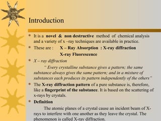
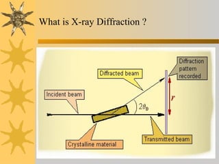

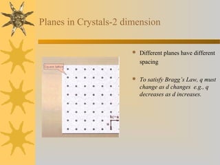
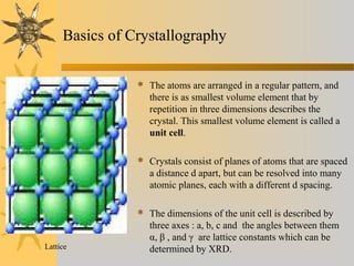
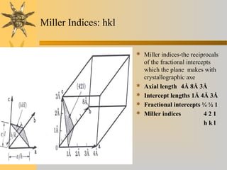
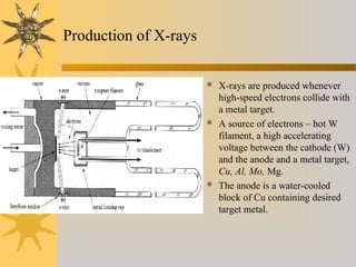
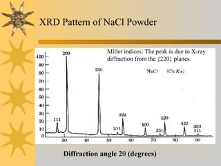
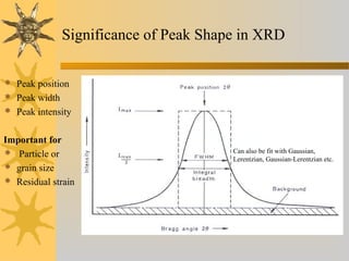
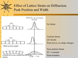
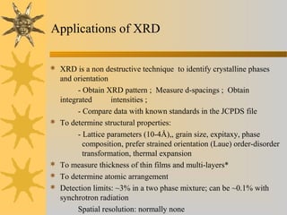


X-ray diffraction (XRD) is a non-destructive chemical analysis method that utilizes the scattering of X-rays by crystals to provide a 'fingerprint' pattern of crystalline substances. It allows for the measurement of atomic spacing, crystal orientation, and structure determination, utilizing principles like Bragg's law. XRD is valuable in various applications, including identifying crystalline phases, analyzing structural properties, and determining particle sizes.