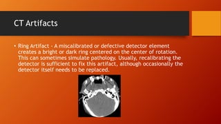
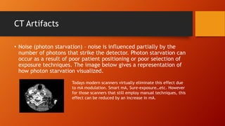
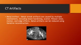
CT Artifacts
Definitions and Solutions
CT Artifacts
• Artifacts can degrade image quality, affect the perceptibility of
detail, or even lead to misdiagnosis. An artifact is a distortion or
error in an image that is unrelated to the subject being imaged.
(Morgan 1983).
• CT artifacts can arise from a number of sources, including the
patient. Inappropriate selection of protocols, reconstruction
processes, equipment malfunction or imperfections, and the
limitation of physics.
CT Artifacts
• Ring Artifact – Ring artifact is caused by a miscalibrated or defective detector
element, which results in rings centered on the center of rotation. This
can often be fixed by recalibrating the detector.
• Noise – Noise is due to the statistical error of low photon counts, and results in
random thin bright and dark streaks that appear preferentially along the
direction of greatest attenuation. Also known as photon starvation.
• Metal artifact – Metal streak artifacts are caused by multiple mechanisms,
including beam hardening, scatter, Poisson noise, motion, and edge effects.
• Beam Hardening - Beam hardening and scatter both produce dark streaks between
two high attenutation objects (such as metal or bone), with surrounding
bright streaks.
• Out of field “artifact” - Out of field “artifacts” are due to a suboptimal
reconstruction algorithm, and can be fixed using a better algorithm.
• Motion - (patient, cardiac, respiratory, bowel) causes blurring and double images, as
well as long range streaks
CT Artifacts
• Ring Artifact - A miscalibrated or defective detector element
creates a bright or dark ring centered on the center of rotation.
This can sometimes simulate pathology. Usually, recalibrating the
detector is sufficient to fix this artifact, although occasionally the
detector itself needs to be replaced.
CT Artifacts
• Noise (photon starvation) – noise is influenced partially by the
number of photons that strike the detector. Photon starvation can
occur as a result of poor patient positioning or poor selection of
exposure techniques. The image below gives a representation of
how photon starvation visualized.
Todays modern scanners virtually eliminate this effect due
to mA modulation. Smart mA, Sure-exposure…etc. However
for those scanners that still employ manual techniques, this
effect can be reduced by an increase in mA.
CT Artifacts
• Metal Artifact - Metal streak artifacts are caused by multiple
mechanisms, including beam hardening, scatter, Poisson noise,
motion, and edge effects. Metal artifacts can be reduced using
iterative reconstruction.
CT Artifacts
• Beam Hardening - Beam hardening in CT arises due to the
polychromatic (varied energies) X-ray beam. As the beam passes
through the body, lower energy photons are attenuated more
easily, and the remaining higher energy photons are not
attenuated as easily causing what we see as an artifact. So by
increasing the overall energy of the beam (kV) we can reduce this
artifact.
CT Artifacts
• Motion – motion artifacts can be anything from voluntary motion
(caused by the patient ie Head movement, improper breathing
etc.) to involuntary motion such as peristalsis or cardiac motion.
Proper patient education can only reduce voluntary motion or by
applying immobilization techniques. Improved techniques such as
faster pitch can reduce the presence of involuntary motion, or as
in cardiac CT a technique that monopolizes the “at rest” portion
of the QRS complex (generally the ST segment). Look for a future
presentation solely devoted to cardiac CT.
CT Artifacts
• Motion Images :
CT Artifacts
• Well there we have it, CT artifacts, certainly this is not a
complete documentation of all CT artifacts but it addresses the
ones that technologists as a whole will see. For a more in depth
understanding of CT Artifacts please follow this link.
• http://www.edboas.com/science/CT/0012.pdf

CT Artifacts

  • 1.
  • 2.
    CT Artifacts • Artifactscan degrade image quality, affect the perceptibility of detail, or even lead to misdiagnosis. An artifact is a distortion or error in an image that is unrelated to the subject being imaged. (Morgan 1983). • CT artifacts can arise from a number of sources, including the patient. Inappropriate selection of protocols, reconstruction processes, equipment malfunction or imperfections, and the limitation of physics.
  • 3.
    CT Artifacts • RingArtifact – Ring artifact is caused by a miscalibrated or defective detector element, which results in rings centered on the center of rotation. This can often be fixed by recalibrating the detector. • Noise – Noise is due to the statistical error of low photon counts, and results in random thin bright and dark streaks that appear preferentially along the direction of greatest attenuation. Also known as photon starvation. • Metal artifact – Metal streak artifacts are caused by multiple mechanisms, including beam hardening, scatter, Poisson noise, motion, and edge effects. • Beam Hardening - Beam hardening and scatter both produce dark streaks between two high attenutation objects (such as metal or bone), with surrounding bright streaks. • Out of field “artifact” - Out of field “artifacts” are due to a suboptimal reconstruction algorithm, and can be fixed using a better algorithm. • Motion - (patient, cardiac, respiratory, bowel) causes blurring and double images, as well as long range streaks
  • 4.
    CT Artifacts • RingArtifact - A miscalibrated or defective detector element creates a bright or dark ring centered on the center of rotation. This can sometimes simulate pathology. Usually, recalibrating the detector is sufficient to fix this artifact, although occasionally the detector itself needs to be replaced.
  • 5.
    CT Artifacts • Noise(photon starvation) – noise is influenced partially by the number of photons that strike the detector. Photon starvation can occur as a result of poor patient positioning or poor selection of exposure techniques. The image below gives a representation of how photon starvation visualized. Todays modern scanners virtually eliminate this effect due to mA modulation. Smart mA, Sure-exposure…etc. However for those scanners that still employ manual techniques, this effect can be reduced by an increase in mA.
  • 6.
    CT Artifacts • MetalArtifact - Metal streak artifacts are caused by multiple mechanisms, including beam hardening, scatter, Poisson noise, motion, and edge effects. Metal artifacts can be reduced using iterative reconstruction.
  • 7.
    CT Artifacts • BeamHardening - Beam hardening in CT arises due to the polychromatic (varied energies) X-ray beam. As the beam passes through the body, lower energy photons are attenuated more easily, and the remaining higher energy photons are not attenuated as easily causing what we see as an artifact. So by increasing the overall energy of the beam (kV) we can reduce this artifact.
  • 8.
    CT Artifacts • Motion– motion artifacts can be anything from voluntary motion (caused by the patient ie Head movement, improper breathing etc.) to involuntary motion such as peristalsis or cardiac motion. Proper patient education can only reduce voluntary motion or by applying immobilization techniques. Improved techniques such as faster pitch can reduce the presence of involuntary motion, or as in cardiac CT a technique that monopolizes the “at rest” portion of the QRS complex (generally the ST segment). Look for a future presentation solely devoted to cardiac CT.
  • 9.
  • 10.
    CT Artifacts • Wellthere we have it, CT artifacts, certainly this is not a complete documentation of all CT artifacts but it addresses the ones that technologists as a whole will see. For a more in depth understanding of CT Artifacts please follow this link. • http://www.edboas.com/science/CT/0012.pdf