Download to read offline


![How to visualize the occurrence of peaks at various angles
It is ‘somewhat difficult’ to actually visualize a random assembly of crystallites giving peaks at various angels in a XRD scan.
The figures below are expected to give a ‘visual feel’ for the same. [Hypothetical crystal with a = 4Å is assumed with
=1.54Å. Only planes of the type xx0 (like (100,110)are considered].
Random assemblage of
crystallites in a material
As the scan takes place at increasing
angles, planes with suitable ‘d’,
which diffract are ‘picked out’ from
favourably oriented crystallites
h2 hkl d Sin()
1 100 4.00 0.19 11.10
2 110 2.83 0.27 15.80
3 111 2.31 0.33 19.48
4 200 2.00 0.39 22.64
5 210 1.79 0.43 25.50
6 211 1.63 0.47 28.13
8 220 1.41 0.54 32.99
9 300 1.33 0.58 35.27
10 310 1.26 0.61 37.50
For convenience the source
may be stationary (and the
sample and detector may
rotate– but the effect is
equivalent)](https://image.slidesharecdn.com/adityasharma-170407140735/85/X-RAY-Aditya-sharma-19-320.jpg)
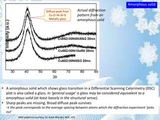


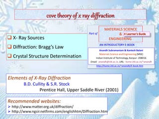
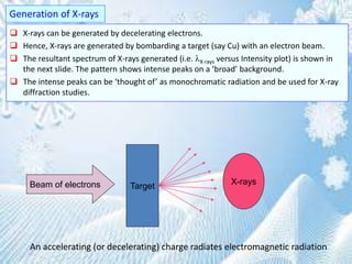
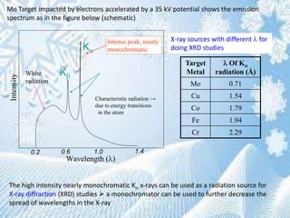
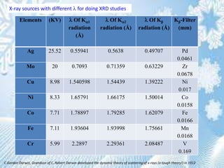
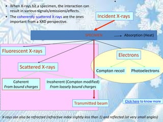
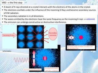
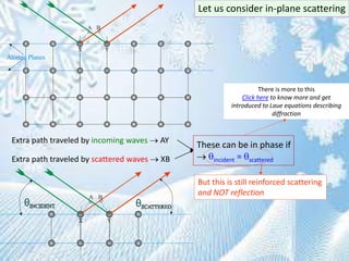
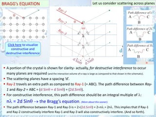
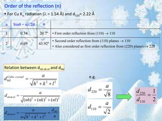
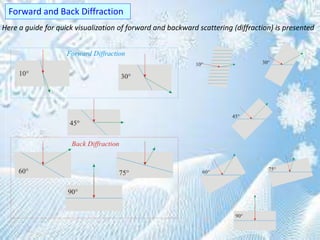
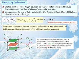
This document provides information on the Bragg's law of X-ray diffraction. It begins with an introduction to X-ray sources and generation, including how X-rays are produced by bombarding a target with electrons. It then explains Bragg's law of diffraction, which relates the scattering angle, wavelength of radiation, and interplanar spacing. The rest of the document discusses crystal structure determination using X-ray diffraction, including diagrams demonstrating Bragg's law and the conditions for constructive interference. It also addresses common questions around visualizing diffraction and obtaining Angstrom-scale information.