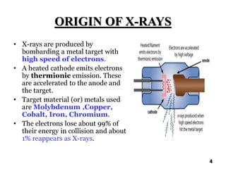
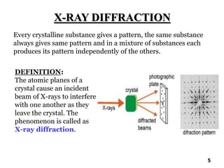
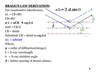
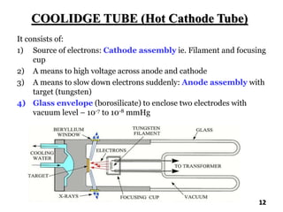
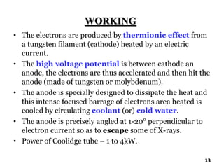
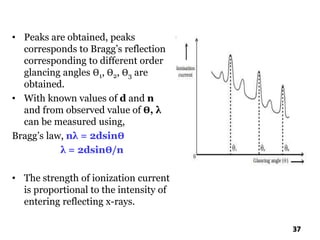
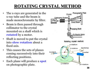
The document discusses various methods of x-ray analysis. It begins by describing how x-rays are produced using a Coolidge tube, which generates x-rays by accelerating electrons into a metal target. It then discusses several x-ray techniques including x-ray diffraction, which is based on constructive interference of x-rays scattered by crystal lattices and is governed by Bragg's law. Finally, it summarizes common methods for x-ray diffraction analysis including transmission methods, back-reflection methods, and Bragg's x-ray spectrometer method which measures diffraction intensities using a rotating crystal.
In this slide contains Principle, Methods, Interpretation and applications of XRD.
Presented by: Udit Narayan Singh (Department of pharmaceutics)
RIPER, anantpur.
Fourier transform infrared spectroscopy: advantage and disadvantage of conventional infrared spectroscopy, introduction to FTIR ,principle of FTIR, working, advantage, disadvantage and application of FTIR.
Fourier Transform Infrared Spectroscopy-:A type of infrared spectroscopy.It is method of obtaining an infrared spectrum by measuring interferogram and then performimg a Fourier Transform upon the interferogram to obtain the spectrum.
Its a theoretical content for Pharmacy graduates, post graduates in pharmacy and Doctor of Pharmacy And also M Sc Instrumentation, UG and PG of Ayurveda medical students, MS etc.
Spin-lattice & spin-spin relaxation, signal splitting & signal multiplicity concepts briefly explained relevant to Nuclear Magnetic Resonance Spectroscopy.
Palestine last event orientationfvgnh .pptxRaedMohamed3
An EFL lesson about the current events in Palestine. It is intended to be for intermediate students who wish to increase their listening skills through a short lesson in power point.
Honest Reviews of Tim Han LMA Course Program.pptxtimhan337
Personal development courses are widely available today, with each one promising life-changing outcomes. Tim Han’s Life Mastery Achievers (LMA) Course has drawn a lot of interest. In addition to offering my frank assessment of Success Insider’s LMA Course, this piece examines the course’s effects via a variety of Tim Han LMA course reviews and Success Insider comments.
Operation “Blue Star” is the only event in the history of Independent India where the state went into war with its own people. Even after about 40 years it is not clear if it was culmination of states anger over people of the region, a political game of power or start of dictatorial chapter in the democratic setup.
The people of Punjab felt alienated from main stream due to denial of their just demands during a long democratic struggle since independence. As it happen all over the word, it led to militant struggle with great loss of lives of military, police and civilian personnel. Killing of Indira Gandhi and massacre of innocent Sikhs in Delhi and other India cities was also associated with this movement.
Introduction to AI for Nonprofits with Tapp NetworkTechSoup
Dive into the world of AI! Experts Jon Hill and Tareq Monaur will guide you through AI's role in enhancing nonprofit websites and basic marketing strategies, making it easy to understand and apply.
Macroeconomics- Movie Location
This will be used as part of your Personal Professional Portfolio once graded.
Objective:
Prepare a presentation or a paper using research, basic comparative analysis, data organization and application of economic information. You will make an informed assessment of an economic climate outside of the United States to accomplish an entertainment industry objective.
June 3, 2024 Anti-Semitism Letter Sent to MIT President Kornbluth and MIT Cor...Levi Shapiro
Letter from the Congress of the United States regarding Anti-Semitism sent June 3rd to MIT President Sally Kornbluth, MIT Corp Chair, Mark Gorenberg
Dear Dr. Kornbluth and Mr. Gorenberg,
The US House of Representatives is deeply concerned by ongoing and pervasive acts of antisemitic
harassment and intimidation at the Massachusetts Institute of Technology (MIT). Failing to act decisively to ensure a safe learning environment for all students would be a grave dereliction of your responsibilities as President of MIT and Chair of the MIT Corporation.
This Congress will not stand idly by and allow an environment hostile to Jewish students to persist. The House believes that your institution is in violation of Title VI of the Civil Rights Act, and the inability or
unwillingness to rectify this violation through action requires accountability.
Postsecondary education is a unique opportunity for students to learn and have their ideas and beliefs challenged. However, universities receiving hundreds of millions of federal funds annually have denied
students that opportunity and have been hijacked to become venues for the promotion of terrorism, antisemitic harassment and intimidation, unlawful encampments, and in some cases, assaults and riots.
The House of Representatives will not countenance the use of federal funds to indoctrinate students into hateful, antisemitic, anti-American supporters of terrorism. Investigations into campus antisemitism by the Committee on Education and the Workforce and the Committee on Ways and Means have been expanded into a Congress-wide probe across all relevant jurisdictions to address this national crisis. The undersigned Committees will conduct oversight into the use of federal funds at MIT and its learning environment under authorities granted to each Committee.
• The Committee on Education and the Workforce has been investigating your institution since December 7, 2023. The Committee has broad jurisdiction over postsecondary education, including its compliance with Title VI of the Civil Rights Act, campus safety concerns over disruptions to the learning environment, and the awarding of federal student aid under the Higher Education Act.
• The Committee on Oversight and Accountability is investigating the sources of funding and other support flowing to groups espousing pro-Hamas propaganda and engaged in antisemitic harassment and intimidation of students. The Committee on Oversight and Accountability is the principal oversight committee of the US House of Representatives and has broad authority to investigate “any matter” at “any time” under House Rule X.
• The Committee on Ways and Means has been investigating several universities since November 15, 2023, when the Committee held a hearing entitled From Ivory Towers to Dark Corners: Investigating the Nexus Between Antisemitism, Tax-Exempt Universities, and Terror Financing. The Committee followed the hearing with letters to those institutions on January 10, 202
Embracing GenAI - A Strategic ImperativePeter Windle
Artificial Intelligence (AI) technologies such as Generative AI, Image Generators and Large Language Models have had a dramatic impact on teaching, learning and assessment over the past 18 months. The most immediate threat AI posed was to Academic Integrity with Higher Education Institutes (HEIs) focusing their efforts on combating the use of GenAI in assessment. Guidelines were developed for staff and students, policies put in place too. Innovative educators have forged paths in the use of Generative AI for teaching, learning and assessments leading to pockets of transformation springing up across HEIs, often with little or no top-down guidance, support or direction.
This Gasta posits a strategic approach to integrating AI into HEIs to prepare staff, students and the curriculum for an evolving world and workplace. We will highlight the advantages of working with these technologies beyond the realm of teaching, learning and assessment by considering prompt engineering skills, industry impact, curriculum changes, and the need for staff upskilling. In contrast, not engaging strategically with Generative AI poses risks, including falling behind peers, missed opportunities and failing to ensure our graduates remain employable. The rapid evolution of AI technologies necessitates a proactive and strategic approach if we are to remain relevant.
2. X-RAYS
• X-rays were discovered by Wilhelm Roentgen, who called
them X-rays because the nature at first was unknown so, X-rays
are also called as Roentgen rays.
• The penetrating power of X-rays depends on energy also, there
are two types of X-rays. They are,
1) Hard X-rays: which have high frequency and have more
energy
2) Soft X-rays: which have less penetrating and have low energy
• X-rays are short wavelength electromagnetic radiations
produced by the deceleration of high energy electrons (or) by
electronic transitions of electrons in the inner orbital of atoms.
• X-ray region – 0.1 to 100 A°
• Analytical purpose – 0.7 to 2 A°
2
3. X-RAY TECHNIQUES
1) X-ray absorption methods : A beam of x-ray is passed
through a sample, a fraction of x-ray photon absorbed is a
measure of concentration of absorbing substance.
2) X-ray diffraction methods: This is based on scattering of
x-ray by crystals.
3) X-ray fluorescence methods : It is the emission of
characteristic “secondary X-rays” from a material that has
been excited by bombarding with high energy X-rays. It is
used for qualitative and quantitative analysis of larger
fractions of geological materials like rock, minerals, sand,
etc..,
3
4. ORIGIN OF X-RAYS
• X-rays are produced by
bombarding a metal target with
high speed of electrons.
• A heated cathode emits electrons
by thermionic emission. These
are accelerated to the anode and
the target.
• Target material (or) metals used
are Molybdenum ,Copper,
Cobalt, Iron, Chromium.
• The electrons lose about 99% of
their energy in collision and about
1% reappears as X-rays.
4
5. X-RAY DIFFRACTION
Every crystalline substance gives a pattern, the same substance
always gives same pattern and in a mixture of substances each
produces its pattern independently of the others.
5
DEFINITION:
The atomic planes of a
crystal cause an incident
beam of X-rays to interfere
with one another as they
leave the crystal. The
phenomenon is called as
X-ray diffraction.
6. 1) When a beam of x-ray is incident upon a substance ,the
electrons constituting the atoms of the substance become as
small oscillators.
2) These on oscillating at the same frequency as that of incident
x-radiation emit EMR in all directions at the same frequency as
incident X-radiation.
3) The scattered waves are coming from electrons which are
arranged in a regular manner in a crystal lattice & then
travelling in certain directions.
4) If these waves undergo constructive interference they are
said to be diffracted in the plane.
5) The diffracted beams are referred as reflections.
6) Constructive interference of the reflected beams emerging from
two different beams emerging from the two different planes
will take place if the path length of two rays is equal to whole
number of wavelengths.
6
7. PRINCIPLE
• X-ray diffraction is based on constructive
interference of monochromatic X-rays and a
crystalline sample.
• Those X-rays are generated by a cathode ray tube,
filtered to produce monochromatic radiation,
collimated to concentrate and directed towards the
sample.
• The interaction of incident rays with the sample
produces constructive interference when conditions
satisfy Bragg’s law.
7
8. BRAGG’S LAW
• The conditions for diffraction are governed by Bragg’s law.
• Constructive interference of the reflected beams
emerging from two different beams emerging from the two
different planes will take place if the path length of two rays is
equal to whole number of wavelengths.
• If one x-ray is striking from the top crystal plane at A &the
other x-ray is striking the second crystal lane at B ,the path
difference between two parallel x-ray is equal to CB+BD from
the planes with spacing d at an angle Ө.
• The path difference between the ray 1 and ray 2 = 2d sinӨ
8
9. BRAGG’S LAW DERIVATION:
For constructive interference,
n = CB+BD
CB=BD
n = 2CB eq.(1)
sin = CB/d
CB = dsin
Substitute CB = dsin in eq.(1)
n = 2dsin
Where,
n = order of diffraction(integer)
= X-ray wavelength
= X-ray incident angle
d = lattice spacing of atomic planes.
9
10. INSTRUMENTATION
10
1) X-ray source
2) Collimator
3) Monochromator
a. Filter
b. Crystal
monochromator
4) Sample and sample
holder
5) Detector
a. Photographic methods
b. Counter methods
11. X-RAY SOURCE
• X rays are generated when a high velocity electrons
impinge on a metal target.
• X-rays are produced by an X-ray tube.
• The various types of X-ray tube includes,
1) Gas discharge/Crookes tube
2) Regulator tube
3) Vacuum tube
4) Coolidge tube
5) Shockproof dental X-ray unit
• Coolidge tube is mostly used for XRD.
11
12. COOLIDGE TUBE (Hot Cathode Tube)
It consists of:
1) Source of electrons: Cathode assembly ie. Filament and focusing
cup
2) A means to high voltage across anode and cathode
3) A means to slow down electrons suddenly: Anode assembly with
target (tungsten)
4) Glass envelope (borosilicate) to enclose two electrodes with
vacuum level – 10-7 to 10-8 mmHg
12
13. WORKING
• The electrons are produced by thermionic effect from
a tungsten filament (cathode) heated by an electric
current.
• The high voltage potential is between cathode an
anode, the electrons are thus accelerated and then hit the
anode (made of tungsten or molybdenum).
• The anode is specially designed to dissipate the heat and
this intense focused barrage of electrons area heated is
cooled by circulating coolant (or) cold water.
• The anode is precisely angled at 1-20° perpendicular to
electron current so as to escape some of X-rays.
• Power of Coolidge tube – 1 to 4kW.
13
14. • The choice of target material depend upon the sample to
be examined.
• Atomic number of target material should be greater
than that of elements being examined in the sample.
• Energy of emitted x-ray should be greater than that
required to excite the elements being irradiated.
DISADVANTAGE:
1) Lack of focusing of electrons, so the whole surface
become a source of x- ray.
14
15. COLLIMATOR
• It is an X-ray beam restrictor device.
• In order to get a narrow beam of X-rays generated by the
target material are allowed to pass through a collimator which
consists of two sets of closely packed metal plates separated by
a small gap.
• Collimator makes random directional X-rays to be narrow
and parallel.
• Usually made up of lead, tungsten, stainless steel and
ceramics.
ADVANTAGES:
• Provides an infinite variety of X-ray fields.
• Light beam shows the centre and the exact configuration of
the X-ray field.
15
16. STRUCTURE
• Two sets of shutters to control the
dimension.
• Each shutter contains 4 or more lead
plates, which move in independent
pairs.
• When the shutters closed they meet at
the centre.
• Light beam from a light bulb in the
collimator.
• The light beam is deflected by a mirror
mounted in the path of the X-ray
beam at an angle of 45°.
• The target of the X-ray tube and the
light bulb should be the exactly same
distance form the centre of the mirror.
16
17. MONOCHROMATOR
Monochromators are device used to convert polychromatic
radiation into monochromatic radiation of desired wavelength.
Inorder to get monochromatization of x-rays, two methods are
available:
1) Filter
2) Crystal Monochromator
a)Flat crystal monochromator
b) Curved crystal monochromator
1) FILTER:
• X-ray beam may be partly monochromatized by insertion of a
suitable filter.
• A filter is a window of material that absorbs undesirable
radiation but allow radiation of required wavelength to
pass.
Eg: Zirconium filter used for molybdenum radiation
17
18. 2) CRYSTAL MONOCHROMATOR:
• It is made up of suitable crystalline material positioned in the
X-ray beam so that the angle of reflecting planes satisfied the
Bragg’s equation for the required wavelength.
• Beam is split by the crystalline material into component
wavelengths.
• Crystals used in monochromators are made up of materials
like NaCl, LiF, Quartz, Graphite, etc..,
There are two types,
a)Flat crystal monochromator
b) Curved crystal monochromator
CHARACTERISTICS OF A CRYSTAL:
1) Mechanically strong and stable
2) The resolution of the crystal should be small
18
21. DETECTOR
• Detection is based on the ability of X-rays to ionize
matter and differ only in the subsequent fate of
electrons produced by the ionizing process.
• The two methods are,
1) Photographic methods (or) imaging detectors
2) Counter methods
a) Geiger–Muller tube counter
b) Proportional counter
c) Scintillation counter
d) Solid state semiconductor detector
e) Semiconductor detectors
21
22. PHOTOGRAPHIC DETECTOR
• To record the position and intensity of X-ray beam a plane
(or) cylindrical film is used.
• The film after exposing to X-ray is developed.
• The blackening of the developed film is expressed in terms of
density units D given by,
D=log Io/I
Where,
Io – incident intensities
I – transmitted intensities
D – total energy that causes blackening of the film
• D is measured by densitometer.
• Photographic methods is mainly used in diffraction studies
since it reveals the entire diffraction pattern on a single
film.
22
23. • Special films used as flat or
cylindrical detectors → beam
appears as dark spots or line.
• Darkening of spot is
proportional to beam
intensity.
• Useful when entire diffraction
pattern is desirable.
ADVANTAGE:
Easy to interpret position of beam
DISADVANTAGES:
• Time consuming
• Exposure of several hours
• Difficult to use for quantitative
intensity data 23
24. COUNTER METHODS
• The counter detector converts the incoming X-rays
into surges (or) pulsed of electric current
which are fed into various electronic components for
processing.
• The electronics counts the number of current pulses
per unit time and this number is directly
proportional to the intensity of the X-ray beam
entering the detector.
24
25. GEIGER MULLER TUBE COUNTER
• Geiger tube is filled with inert
gas like argon.
• Central wire anode is
maintained at a positive
potential of 800-2500V.
• X-ray entering GM tube →
collision with filling gas →
production of an ion pair.
• The electron produced moves
towards the central anode &
positive ion move towards outer
electrode.
25
26. • The electron is accelerated by the potential gradient and
causes the ionisation of large number of argon atoms,
resulting in the production of electrons that are travelling
towards the central anode.
• This results in an output pulse of 1-10V which can be
measured very easily.
ADVANTAGES:
• Inexpensive
• Relatively trouble free
DISADVANTAGES:
• Used for low counting rates
• Efficiency falls off below 1A°
• Cannot be used to measure the energy of ionizing
radiation(no spectrographic information)
26
27. PROPORTIONAL COUNTER
• Construction is similar to Geiger tube counter.
• Proportional counter is filled with heavier gas like
xenon and krypton.
• Heavier gas is preferred because it is easily ionized.
• Operated at a voltage below the Geiger plateau.
• The dead time is very short (~0.2 µs), it can be used to
count high rates without significant error.
ADVANTAGE:
• Counts high rates
DISADVANTAGE:
• Circuit is complex and expensive
27
28. SCINTILLATION DETECTOR
• In a scintillation detector there is large sodium iodide
crystal activated with a small amount of thallium.
• When X-ray is incident upon crystal, the pulse of visible light
are emitted is proportion to X-ray intensity which can be
detected by a photomultiplier tube (PMT).
• The size of pulse is proportional to energy of X-ray photon
absorbed.
• Useful for measuring X-ray of short wavelength.
• Crystals used in scintillation detectors include sodium iodide,
anthracene, naphthalene and p-terpenol.
28
29. SOLID STATE SEMICONDUCTOR
DETECTOR
• Electrons produced by x-ray beam are
promoted into conduction bands.
• Current which flows is directly
proportional to the incident x-ray
energy.
• It consists of a thin layer of n-type
material on the surface of a large piece
of p-type material.
DISADVANTAGE:
• Semiconductor device should be
maintained at low temperature to
minimize the noise & prevent
deterioration.
29
30. SEMICONDUCTOR DETECTOR
• Si (Li) and Ge (Li) are used as
semiconductors.
• When x-ray falls on a silicon lithium
drifted semiconductor, it generates an
electron(-e) and a hole(+e) .
• In this a very pure silicon block is set up
with a thin film of lithium metal plated
onto one end.
• Operates with a combination of p-type
and n-type semiconductor.
• Under the influence of voltage electrons
moves towards +ve charge and holes
towards –ve charge.
30
31. • The voltage generated is a measure of x-ray intensity
falling on the crystal.
• Upon arriving at the lithium coating ,a pulse is
generated.
voltage of pulse=q/c
Where ,
q - total charge collected on electrode
c - detector capacity
No. of pulse = No. of x-ray photons falling on detector
31
32. X-RAY DIFFRACTION METHODS
• These are generally used for investigating the internal
structures and crystal structures of various solid
compounds.
• They are,
1) Laue’s photographic method
1) Transmission method
2) Back reflection method
2) Bragg’s X-ray spectrometer method
3) Rotating crystal method
4) Powder diffraction method
32
33. LAUE’S PHOTOGRAPHIC METHOD
TRANSMISSION METHOD BACK REFLECTION
METHOD
The film is placed behind the crystal
to record beams which are
transmitted through the crystal.
One side of the cone of Laue
reflections is defined by the
transmitted beam.
The film is placed between the X-
ray source and the crystal. The
beams which are diffracted in a
backward direction are recorded.
One side of the cone of Laue
reflections is defined by the
reflected beam.
33
34. TRANSMISSION METHOD BACK REFLECTION
METHOD
The film intersects the cone with the
diffraction spots generally lying on
an ellipse.
The film intersects the cone with the
diffraction spots generally lying on
an hyperbola.
USES:
1) Can be used to orient crystals
for solid state experiments.
2) Most suitable for investigation
of preferred orientation sheet
particularly confirmed to lower
diffraction angles.
3) Also used in determination of
symmetry of single crystals.
USES:
This method is similar to
transmission method, however back
reflection is the only method for the
study of large and thick
specimens.
DISADVANTAGE:
There is uncertainity in the
significance due to
unhomogenous nature of x-rays.
DISADVANTAGE:
Big crystals are required.
34
35. BRAGG’S X-RAY SPECTROMETER
METHOD
• Using Laue’s photograph, Bragg analysed structures of
crystals of NaCl, KCl and ZnS.
• Bragg devised a spectrometer to measure the intensity
of X-ray beam.
• The spectra obtained can be employed for
crystallographic analyses.
• This method is based on Bragg’s law.
35
36. WORKING
36
• Crystal mounted such that Ө = 0° and
ionization is adjusted to receive X-rays.
• X-rays from source → pass from slits
(S1,S2) → falls on crystal ‘C’ (vertically
rotating about its axis) → reflected
beam pass to ionization chamber →
ionization of gas → current measured
by galvanometer → intensity of
reflected X-rays is measured.
• The ionization current is measured for
different values of glancing angle Ө.
• A graph is drawn between the glancing
angle and ionizing current.
37. • Peaks are obtained, peaks
corresponds to Bragg’s reflection
corresponding to different order
glancing angles Ө1, Ө2, Ө3 are
obtained.
• With known values of d and n
and from observed value of Ө, λ
can be measured using,
Bragg’s law, nλ = 2dsinӨ
λ = 2dsinӨ/n
• The strength of ionization current
is proportional to the intensity of
entering reflecting x-rays.
37
38. ROTATING CRYSTAL METHOD
• The x-rays are generated in the
x-ray tube and the beam is
made monochromatic by filter.
• Beam is then passed through
collimator to the crystal
mounted on a shaft which is
rotated by a motor.
• Shaft is moved to put the crystal
into slow rotation about a
fixed axis.
• This causes the sets of planes
coming successively into their
reflecting positions.
• Each plane will produce a spot
on photographic plate.
38
39. Photograph can be taken by,
1) Complete rotation method:
• A series of complete revolutions occur.
• Each set of a plane in a crystal diffracts 4 times during
rotation.
• 4 diffracted beams are distributed into a rectangular
pattern in the central point of photograph.
2) Oscillation method:
• The crystal is oscillated at an angle of 15° (or) 20°
• The photographic plate is also moved back and forth with
the crystal.
• The position of the spot on the plate indicates the
orientation of the crystal at which the spot was formed.
39
40. POWDER DIFFRACTION METHOD
• It is a rapid analytical technique primarily used for
phase identification of a crystalline material and can
provide information on unit cell dimensions.
• The analysed material is finely grounded,
homogenised and average bulk composition is
determined.
• 1mg of the sample material is sufficient.
• Unknown crystalline substances can be identified by
comparing the diffraction data with the data of
International Centre for Diffraction Data.
40
41. WORKING:
• X-ray is made monochromatic
by filter & x-ray beam fall on
powdered specimen by passing
through slit.
• Fine powder diffraction is
suspended vertically in the axis
of cylindrical camera.
• Sharp lines are obtained on
photographic film which is
surrounding the powder crystal
in the form of a circular arc.
• X-rays after falling on the
powder passes out of camera
through a cut in the window.
• The diffracted X-rays are
detected.
41
42. When monochromatic beam is allowed to pass different
possibilities may happen,
• There will be some particles out of random orientation of
small crystals in the fine powder.
• Another fraction of grains will have another set of planes in
the correct positions for the reflections to occur.
• Reflections are possible in different orders for each set.
APPLICATIONS:
1) Useful for determining the complex structures of metals and
alloys.
2) Characterization of crystalline materials.
3) Identification of fine-grained minerals such as clays and
mixed layer cells that are difficult to determine optically.
4) Determination of unit cell dimensions.
5) Measurement of sample purity.
42
44. X-RAY DIFFRACTION
ADVANTAGES:
1) X-rays are the least expensive, most convenient and the most
widely used method to determine crystal structures.
2) XRD is a non-destructive technique.
3) X-rays are not absorbed very much by air, so the sample need
not be in an evacuated chamber.
DISADVANTAGES:
1) X-rays do not interact very strongly with lighter elements.
2) X-rays are hazardous to use.
3) XRD has size limitations. It is much more accurate for
measuring large crystalline structures rather than small ones.
(smaller ones that are present only in trace amounts will
often go undetected by XRD readings)
44
45. APPLICATIONS
1) Structure of crystals
• It is a non-destructive method.
• Gives information on molecular structure and size of
crystal planes.
• The patterns obtained are characteristic of a particular
compound from which crystal is formed.
45
46. 2) Polymer characterization
• Determine the degree of
crystallinity.
• A polymer can be considered
partly crystalline and partly
amorphous.
• The crystalline parts give
sharp narrow diffraction
peaks and the amorphous
component gives a very broad
peak.
• The ratio between these
intensities can be used to
calculate the amount of
crystallinity in the material.
46
47. 3) State of anneal in metals.
• XRD is used to test metals without removing the part
from its position and without weakening it.
(Annealing is the heat treatment process that softens a
metal that has been hardened by cold working. At this
stage, any defects caused by deformation of the metal are
repaired. Used to reduce hardness, increase ductility and
help eliminate internal stresses.)
• Well annealed metals are in well ordered form & gives
sharp diffraction lines.
• If the metal is subjected to drilling, hammering or
bending, it becomes fatigued, i.e. its crystals become
broken & the x-ray pattern more diffuse.
• Employed to occasionally check moving parts for metal
fatigue (airplane wings, engine parts).
47
48. 4) Particle size determination.
a) Spot counting methods
b) Broadening of diffraction lines
c) Low-angle scattering methods are used.
Spot counting method:
• For determining particle size >5 microns.
• Powder diffraction pattern consists of a series of lines or rings having a
spotty appearance.
From that we can determine particle size using,
v=V.δӨ.cosӨ/2n
Where, v = volume of individual crystalline
V = total volume irradiated
n =no. of spots in diffraction ring
δӨ = divergence of X-ray beam
Broadening of diffraction line: Used for particles in range of 30-1000Å
Low angle scattering: Used to determine distribution of particle size.
48
49. 5) Applications of diffraction methods to
complexes.
a) Determination of cis-trans isomerism
b) Determination of linkage isomerism
6) Miscellaneous applications:
• Soil classification based on crystallinity
• Analysis of industrial dusts
• Assessment of weathering and degradation of minerals
and polymers
• Study of corrosion products
• Examination of bone state and tissue state
• Examination of tooth enamel and dentine
49