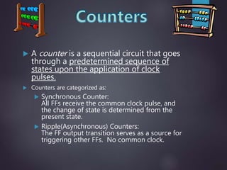
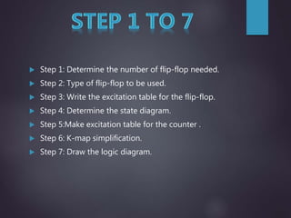
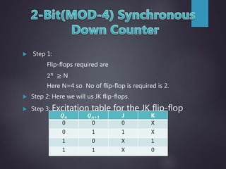
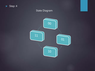
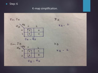
Index
No. Title
1 Introduction of Counter
2 Synchronous Counter
3 Steps 1 to 7
4 2-Bit Synchronous Down Counter
5 3-Bit Synchronous Down Counter
6 Application
 A counter is a sequential circuit that goes
through a predetermined sequence of
states upon the application of clock
pulses.
 Counters are categorized as:
 Synchronous Counter:
All FFs receive the common clock pulse, and
the change of state is determined from the
present state.
 Ripple(Asynchronous) Counters:
The FF output transition serves as a source for
triggering other FFs. No common clock.
 All the flip-flop are clocked simultaneously.
 Synchronous counters can operate at much higher
frequencies than asynchronous counters.
 As clock is simultaneously given to all flip-flops there is no
problem of propagation delay. Hence they are high speed
counters and are preferred when number of flip-flops
increase's in the given design.
 In this counter will counter
 Step 1: Determine the number of flip-flop needed.
 Step 2: Type of flip-flop to be used.
 Step 3: Write the excitation table for the flip-flop.
 Step 4: Determine the state diagram.
 Step 5:Make excitation table for the counter .
 Step 6: K-map simplification.
 Step 7: Draw the logic diagram.
 Step 1:
Flip-flops required are
2 𝑛 ≥ N
Here N=4 so No of flip-flop is required is 2.
 Step 2: Here we will us JK flip-flops.
 Step 3: Excitation table for the JK flip-flop
𝑸 𝒏 𝑸 𝒏+𝟏 J K
0 0 0 X
0 1 1 X
1 0 X 1
1 1 X 0
 Step: 4
State Diagram
 Step: 5
Excitation table for the 2-bit down counter .
Present state Next state Flip-Flop input
𝑸 𝑨
𝑸 𝑩 𝑸 𝑨 + 𝑸 𝑩 + 𝑱 𝑨 𝑲 𝑨 𝑱 𝑩 𝑲 𝑩
0 0 1 1 1 X 1 X
0 1 0 0 0 X X 1
1 0 0 1 X 1 1 X
1 1 1 0 X 0 X 1
 Step: 6
K-map simplification.
 Step: 7
Draw the logic diagram.
 Step 1:
Flip-flops required are
2 𝑛
≥ N
Here N=8 so No of flip-flop is required is 3.
 Step 2: Here we will us T flip-flops.
 Step 3: Excitation table for the T flip-flop
𝑸 𝒏 𝑸 𝒏+𝟏 T
0 0 0
0 1 1
1 0 1
1 1 0
 Step: 4
State Diagram
 Step: 5
Excitation table for the 3-bit down counter .
Present state Next state Flip-Flop input
𝑸 𝑨 𝐐 𝐁 𝐐 𝐂 𝐐 𝐀 + 𝑸 𝑩 + 𝐐 𝐂 + 𝐓 𝐀 𝐓 𝐁 𝐓𝐂
0 0 0 1 1 1 1 1 1
0 0 1 0 0 0 0 0 1
0 1 0 0 0 1 0 1 1
0 1 1 0 1 0 0 0 1
1 0 0 0 1 1 1 1 1
1 0 1 1 0 0 0 0 1
1 1 0 1 0 1 0 1 1
1 1 1 1 1 0 0 0 1
 Step: 6
K-map simplification.
 Step: 7
Draw the logic diagram.
Synchronous down counter

Synchronous down counter

  • 3.
    Index No. Title 1 Introductionof Counter 2 Synchronous Counter 3 Steps 1 to 7 4 2-Bit Synchronous Down Counter 5 3-Bit Synchronous Down Counter 6 Application
  • 4.
     A counteris a sequential circuit that goes through a predetermined sequence of states upon the application of clock pulses.  Counters are categorized as:  Synchronous Counter: All FFs receive the common clock pulse, and the change of state is determined from the present state.  Ripple(Asynchronous) Counters: The FF output transition serves as a source for triggering other FFs. No common clock.
  • 5.
     All theflip-flop are clocked simultaneously.  Synchronous counters can operate at much higher frequencies than asynchronous counters.  As clock is simultaneously given to all flip-flops there is no problem of propagation delay. Hence they are high speed counters and are preferred when number of flip-flops increase's in the given design.  In this counter will counter
  • 6.
     Step 1:Determine the number of flip-flop needed.  Step 2: Type of flip-flop to be used.  Step 3: Write the excitation table for the flip-flop.  Step 4: Determine the state diagram.  Step 5:Make excitation table for the counter .  Step 6: K-map simplification.  Step 7: Draw the logic diagram.
  • 7.
     Step 1: Flip-flopsrequired are 2 𝑛 ≥ N Here N=4 so No of flip-flop is required is 2.  Step 2: Here we will us JK flip-flops.  Step 3: Excitation table for the JK flip-flop 𝑸 𝒏 𝑸 𝒏+𝟏 J K 0 0 0 X 0 1 1 X 1 0 X 1 1 1 X 0
  • 8.
  • 9.
     Step: 5 Excitationtable for the 2-bit down counter . Present state Next state Flip-Flop input 𝑸 𝑨 𝑸 𝑩 𝑸 𝑨 + 𝑸 𝑩 + 𝑱 𝑨 𝑲 𝑨 𝑱 𝑩 𝑲 𝑩 0 0 1 1 1 X 1 X 0 1 0 0 0 X X 1 1 0 0 1 X 1 1 X 1 1 1 0 X 0 X 1
  • 10.
     Step: 6 K-mapsimplification.
  • 11.
     Step: 7 Drawthe logic diagram.
  • 12.
     Step 1: Flip-flopsrequired are 2 𝑛 ≥ N Here N=8 so No of flip-flop is required is 3.  Step 2: Here we will us T flip-flops.  Step 3: Excitation table for the T flip-flop 𝑸 𝒏 𝑸 𝒏+𝟏 T 0 0 0 0 1 1 1 0 1 1 1 0
  • 13.
  • 14.
     Step: 5 Excitationtable for the 3-bit down counter . Present state Next state Flip-Flop input 𝑸 𝑨 𝐐 𝐁 𝐐 𝐂 𝐐 𝐀 + 𝑸 𝑩 + 𝐐 𝐂 + 𝐓 𝐀 𝐓 𝐁 𝐓𝐂 0 0 0 1 1 1 1 1 1 0 0 1 0 0 0 0 0 1 0 1 0 0 0 1 0 1 1 0 1 1 0 1 0 0 0 1 1 0 0 0 1 1 1 1 1 1 0 1 1 0 0 0 0 1 1 1 0 1 0 1 0 1 1 1 1 1 1 1 0 0 0 1
  • 15.
     Step: 6 K-mapsimplification.
  • 16.
     Step: 7 Drawthe logic diagram.