Digital Logic Design (EEEg4302)
Chapter 7 : Counters
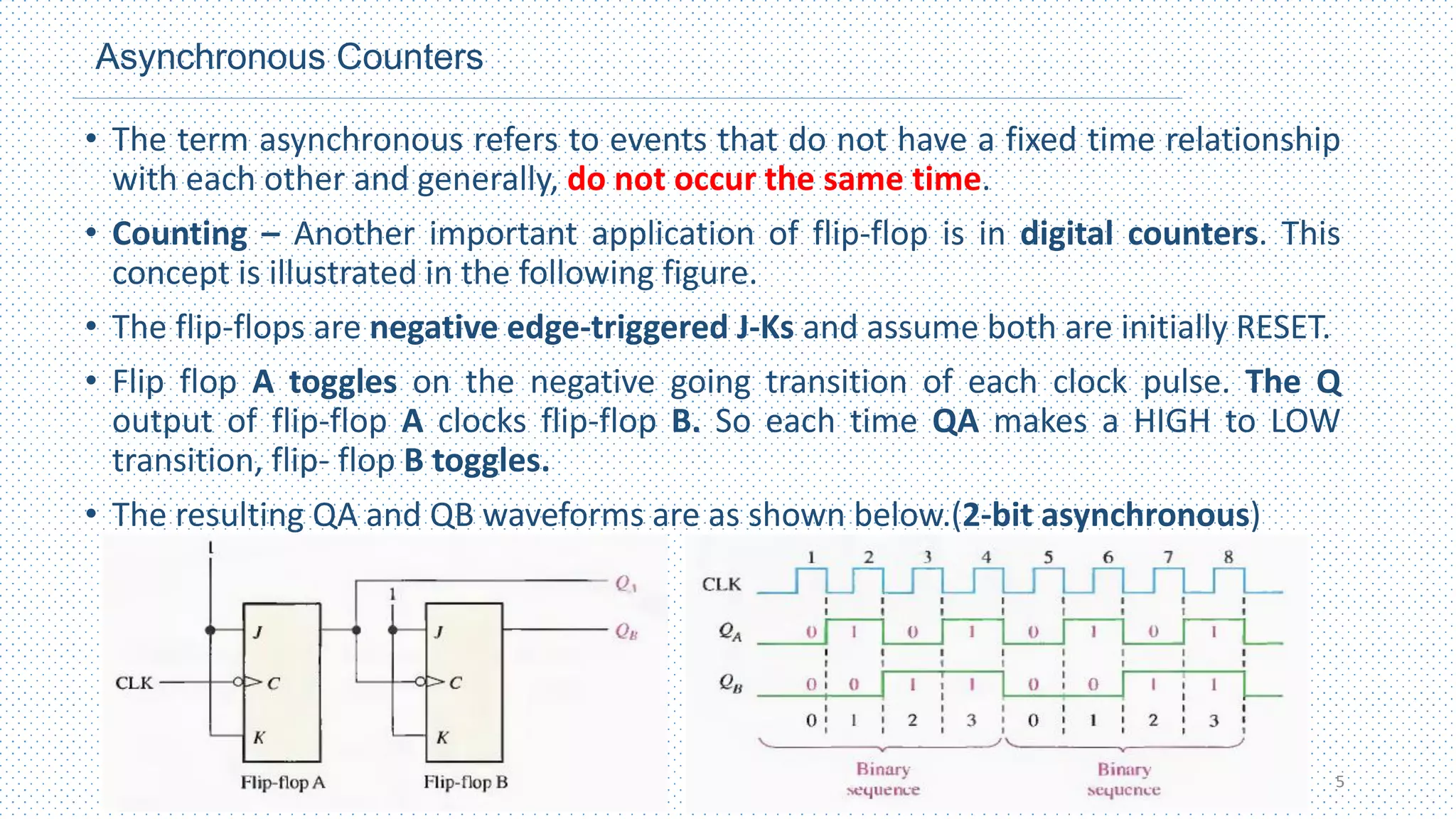
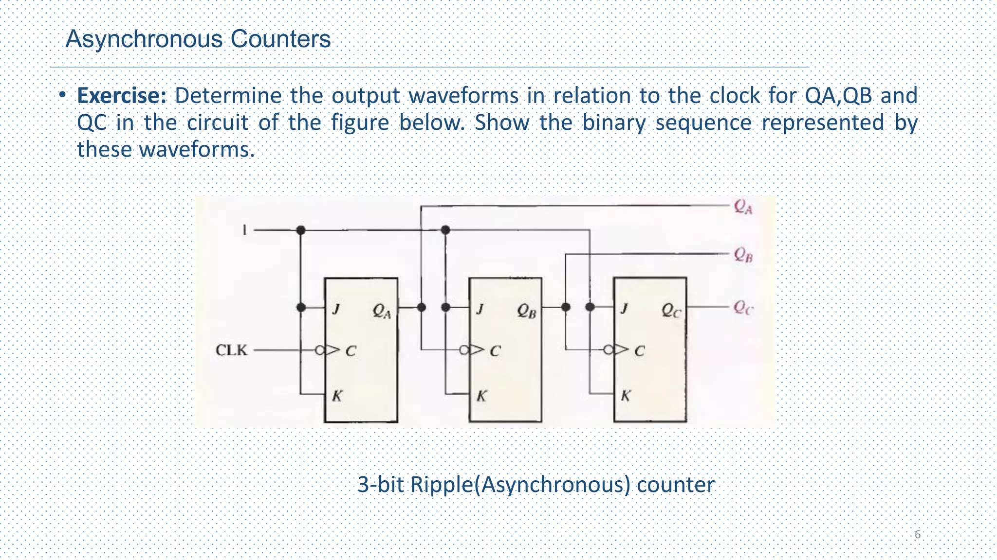
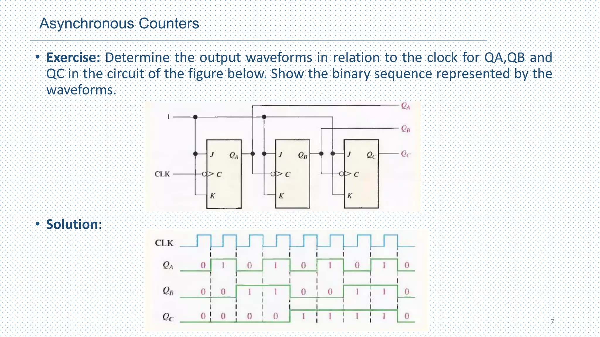
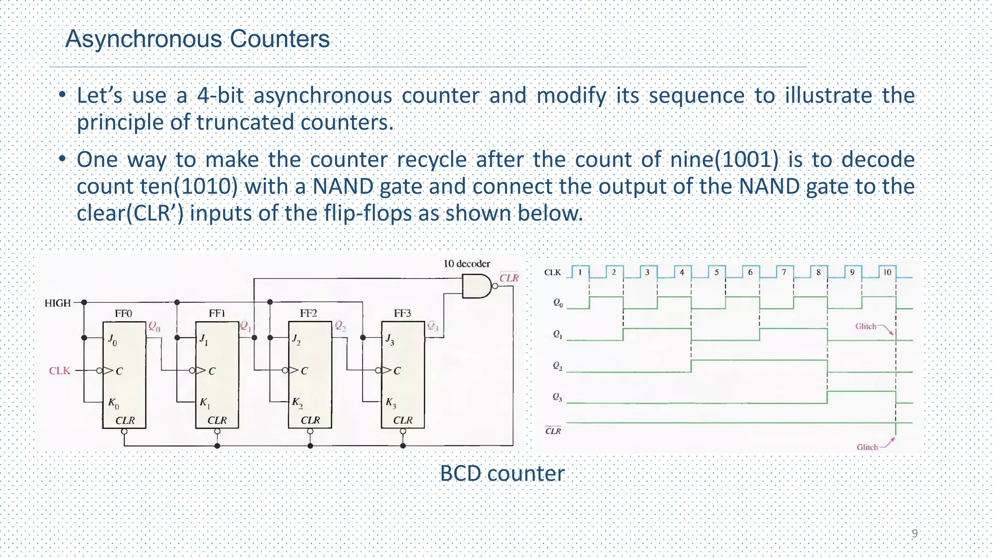
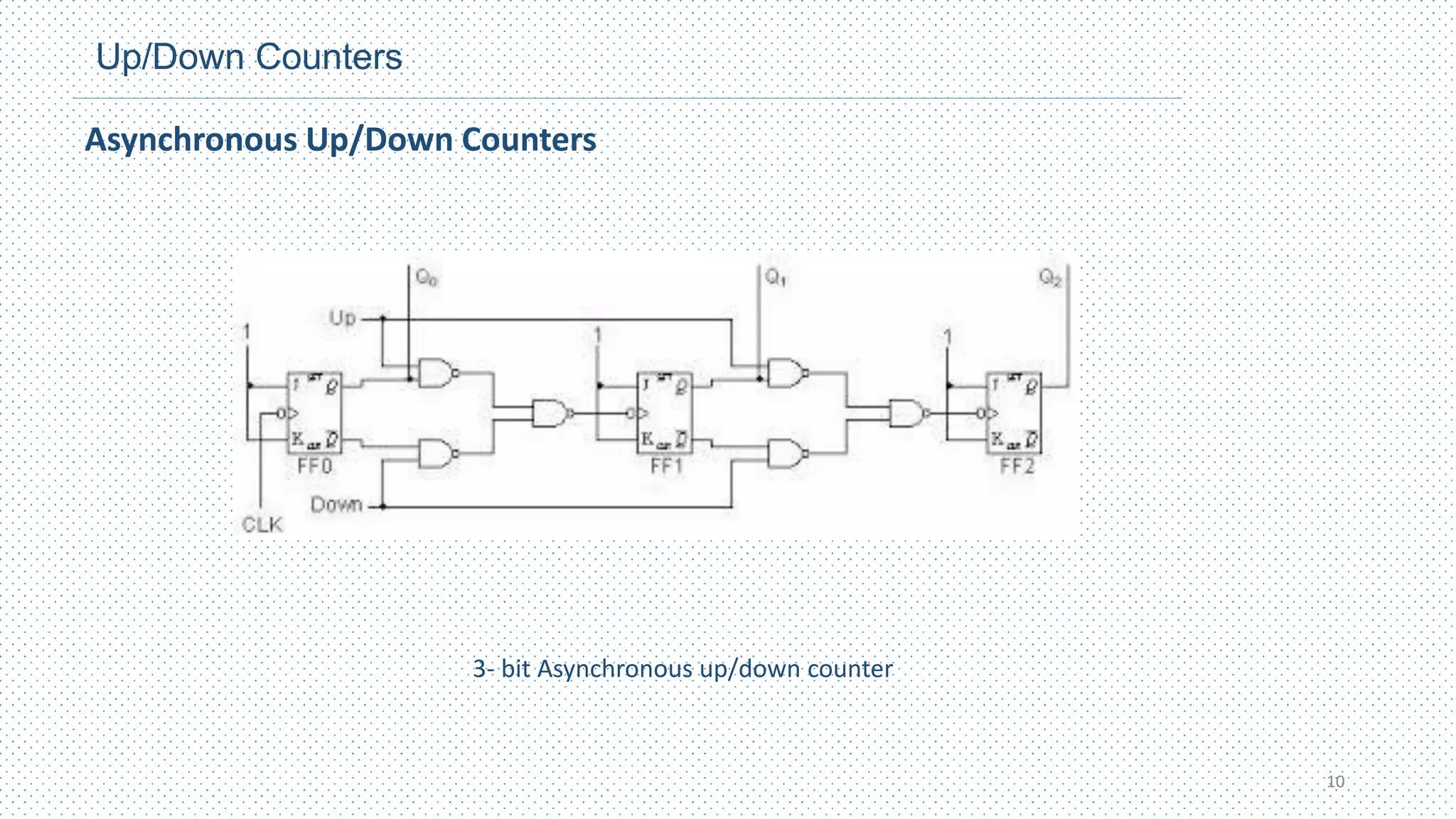
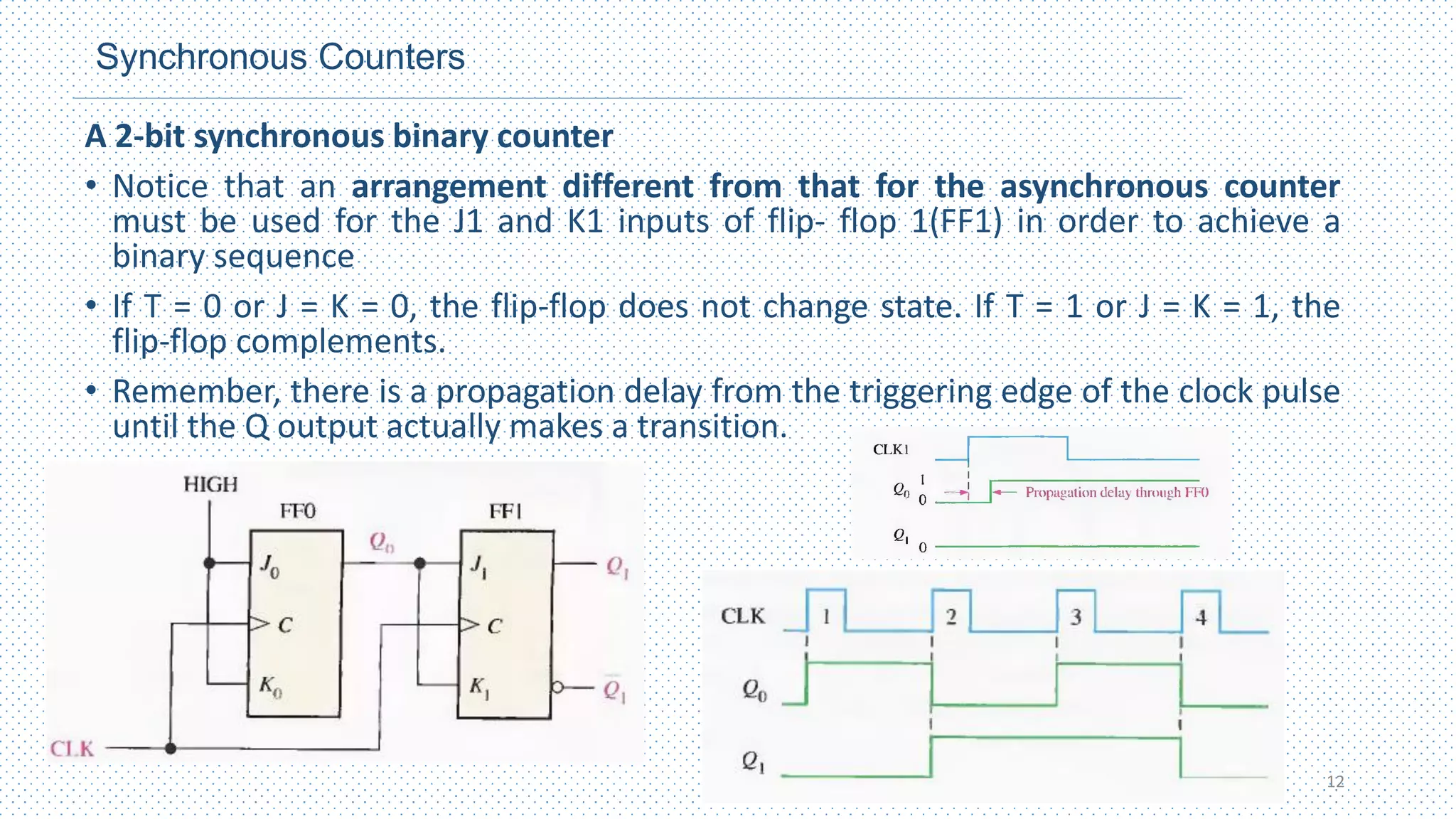
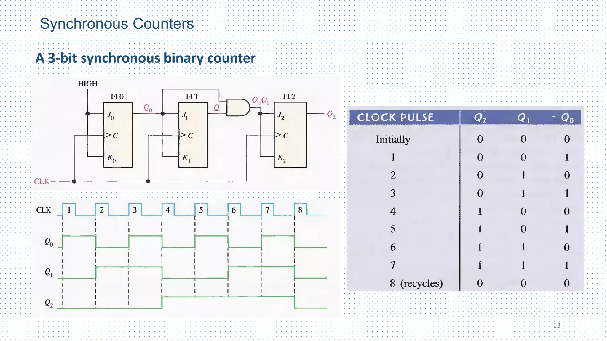
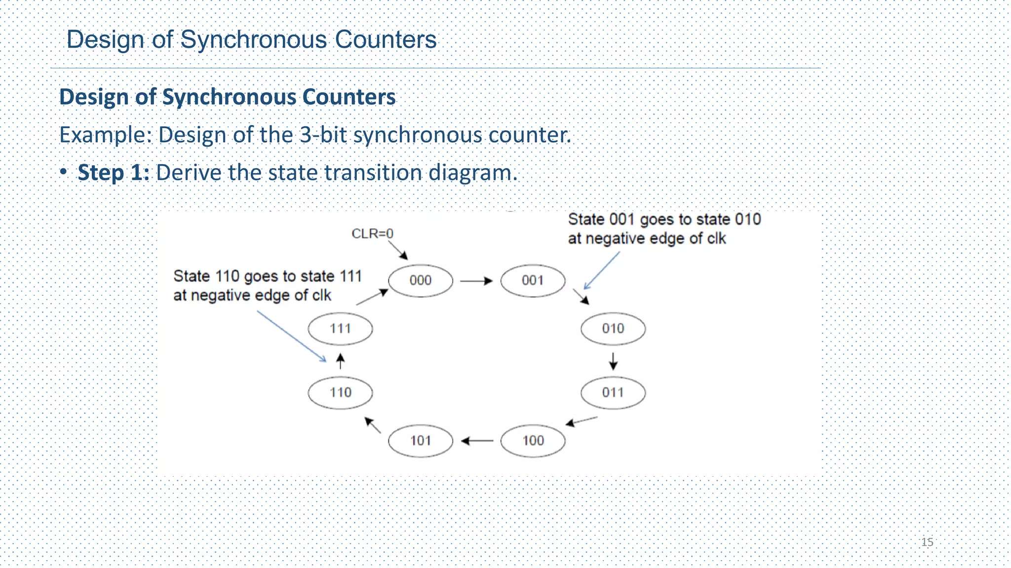
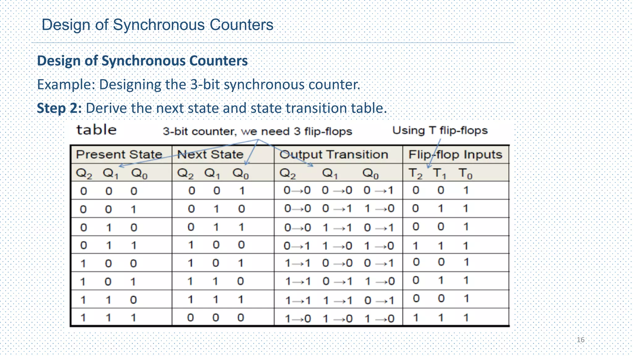
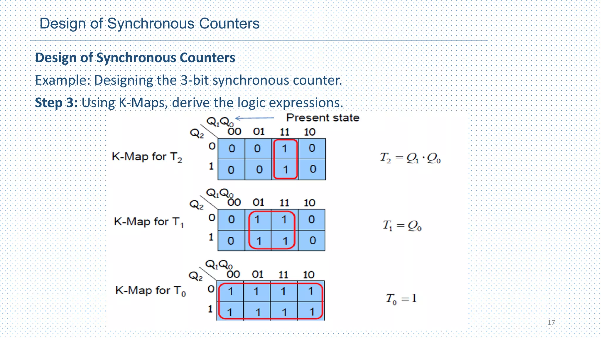
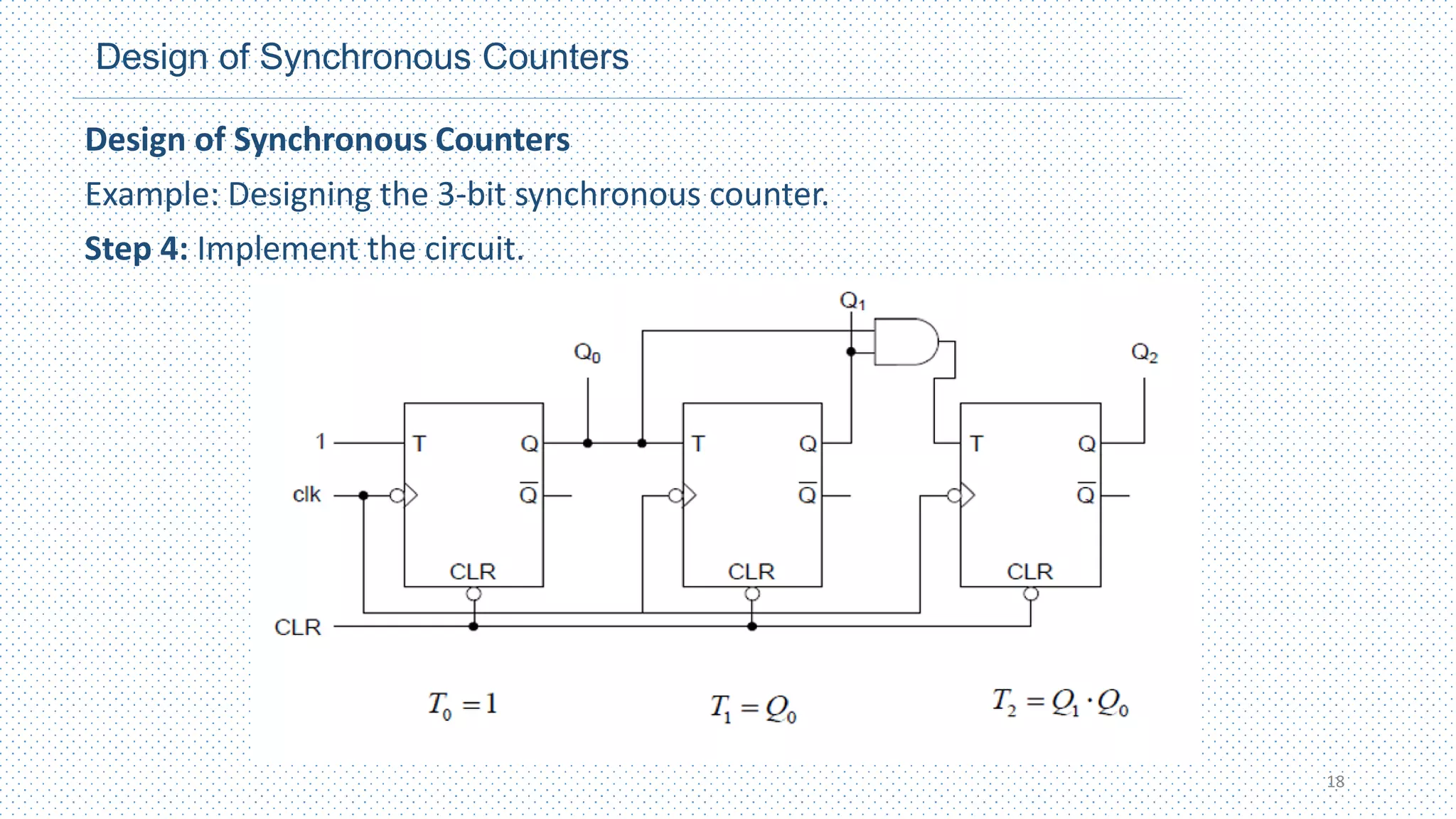
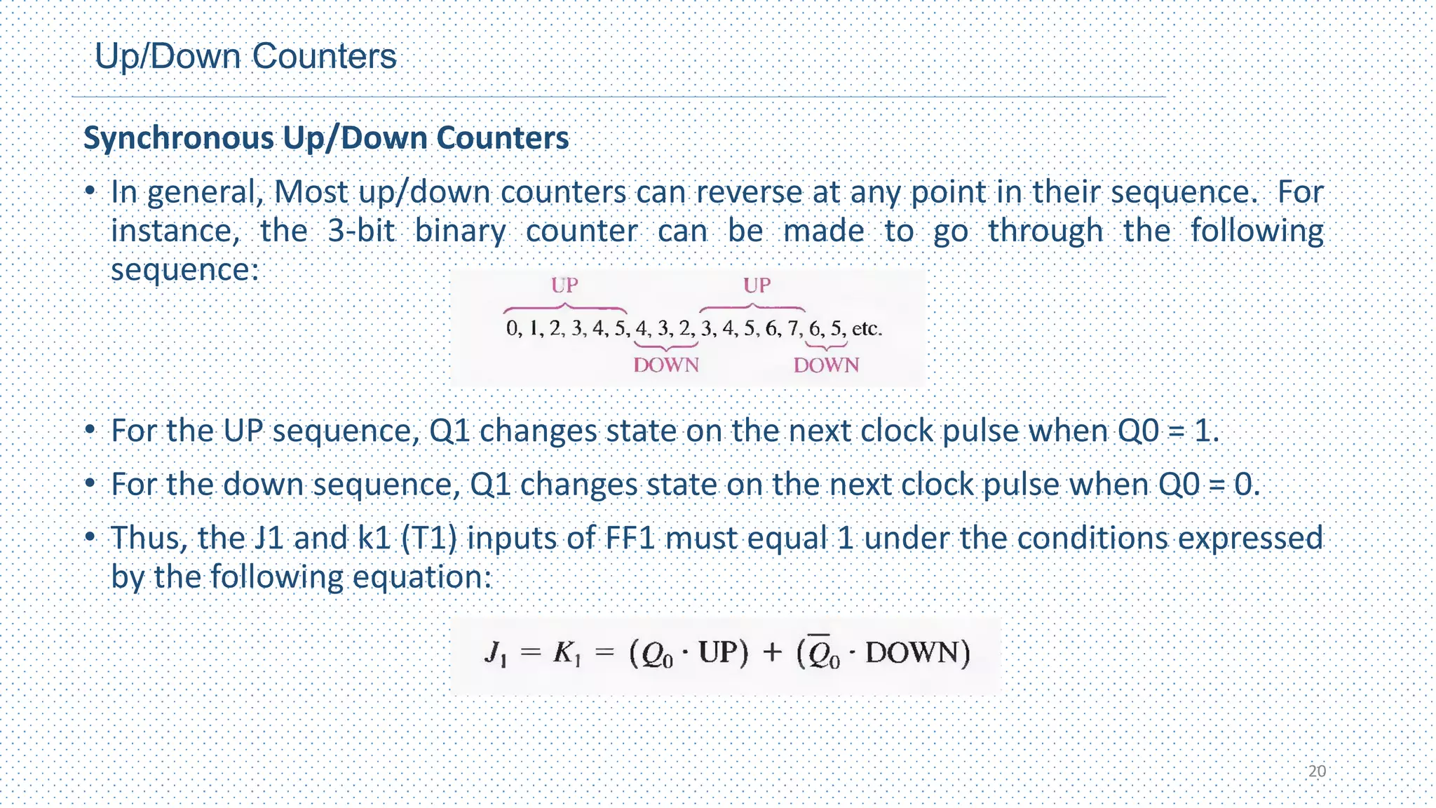
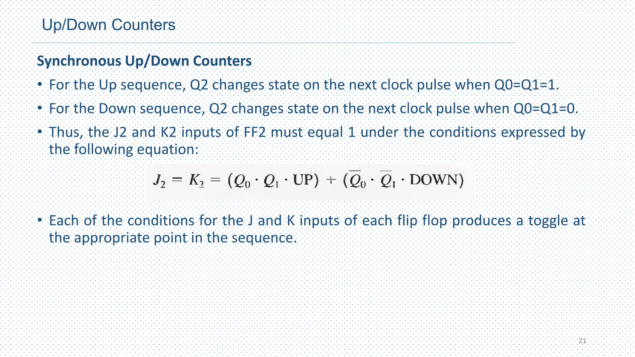
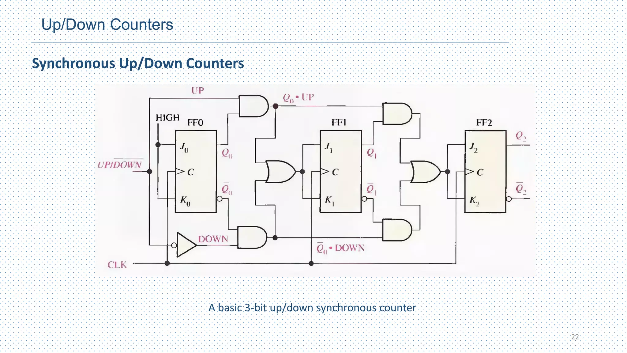
This chapter discusses different types of counters, including asynchronous (ripple) counters and synchronous counters. Asynchronous counters use a ripple effect where one flip-flop triggers the next. Synchronous counters use a common clock signal to trigger all flip-flops simultaneously. The chapter also covers up/down counters, which can count up or down based on control signals, and methods for designing synchronous counters through state diagrams and logic expressions.