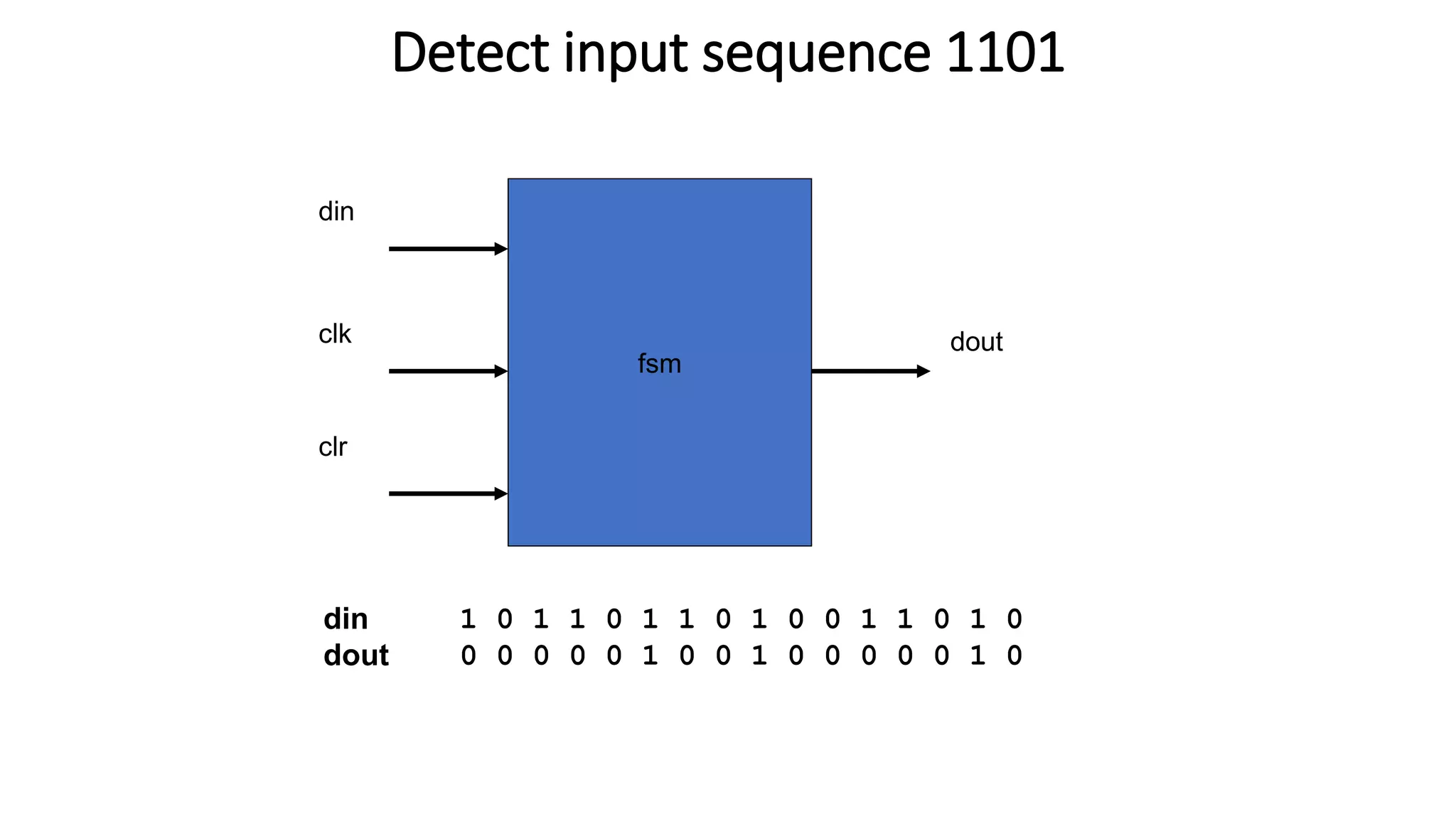
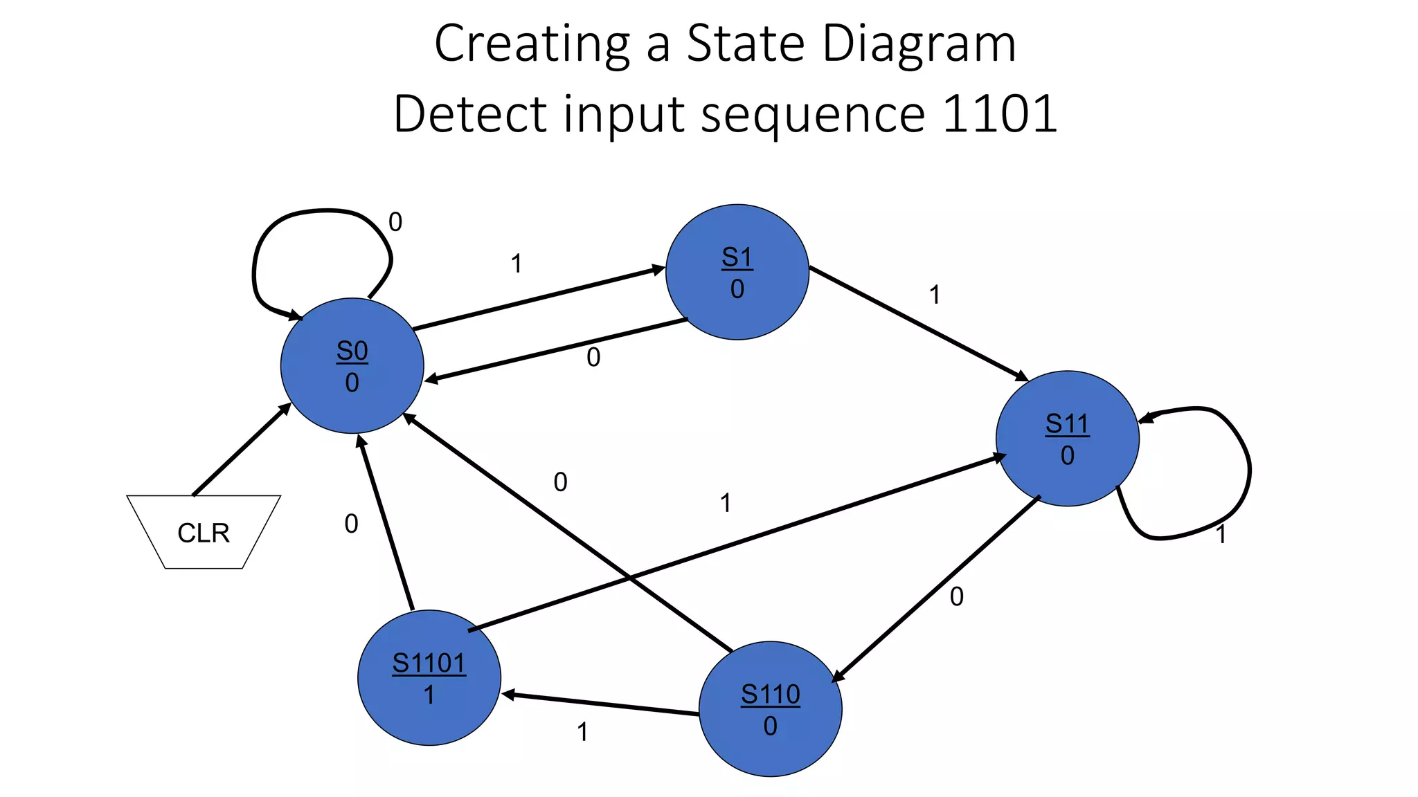
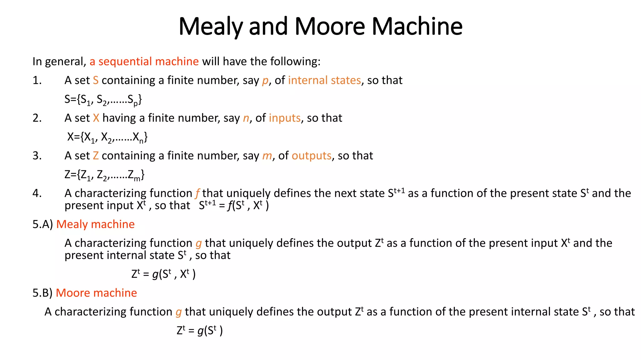
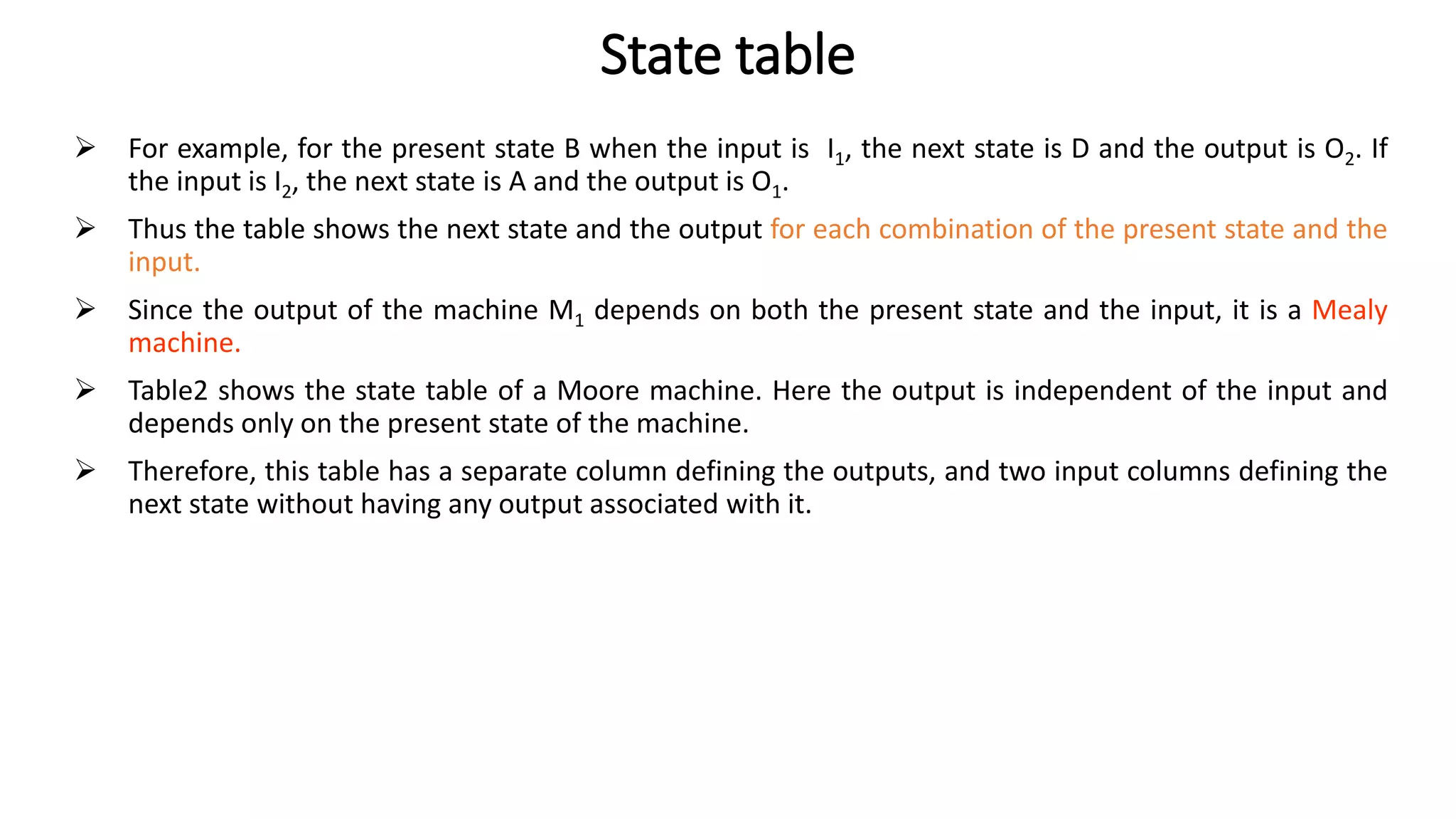
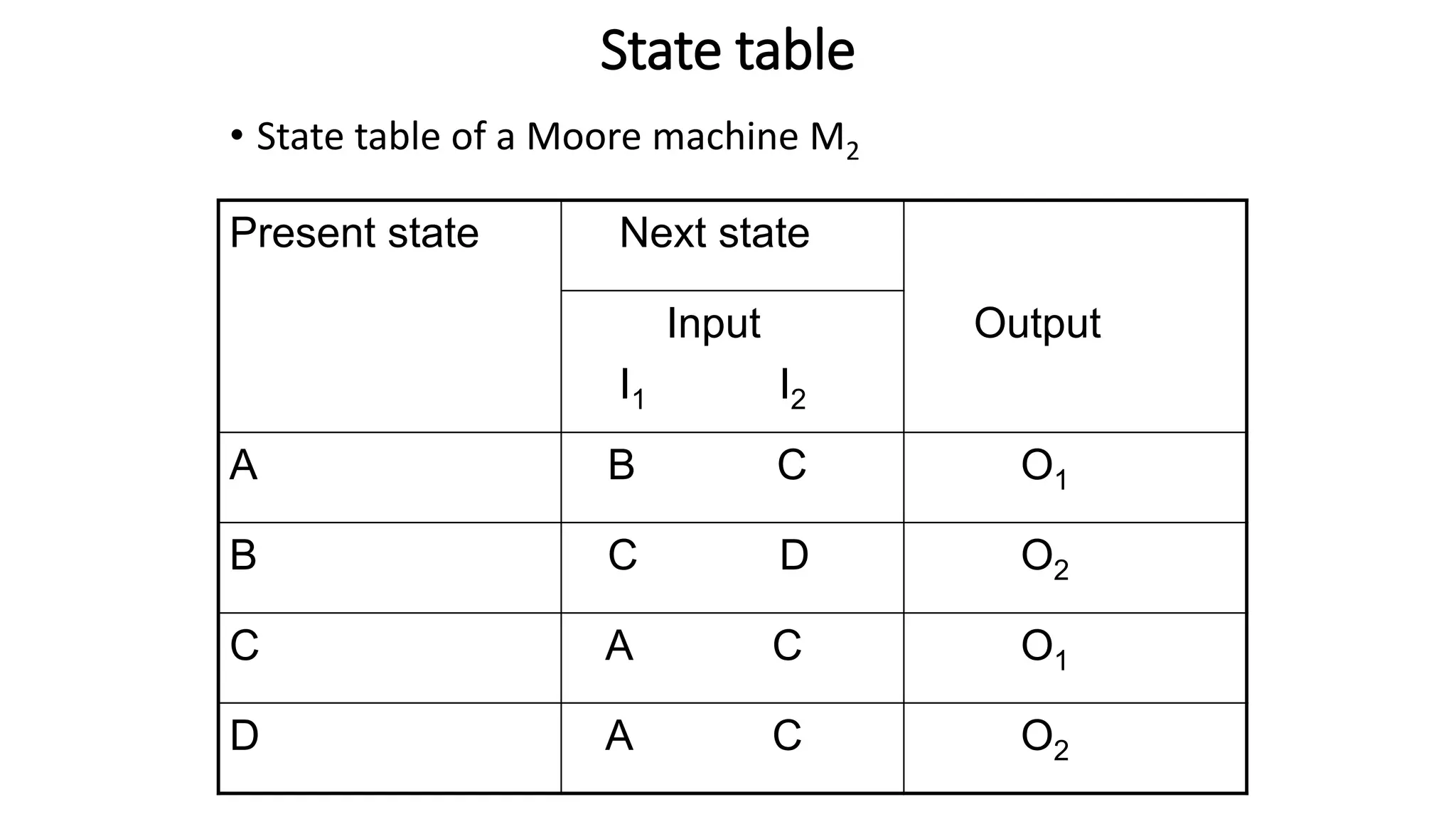
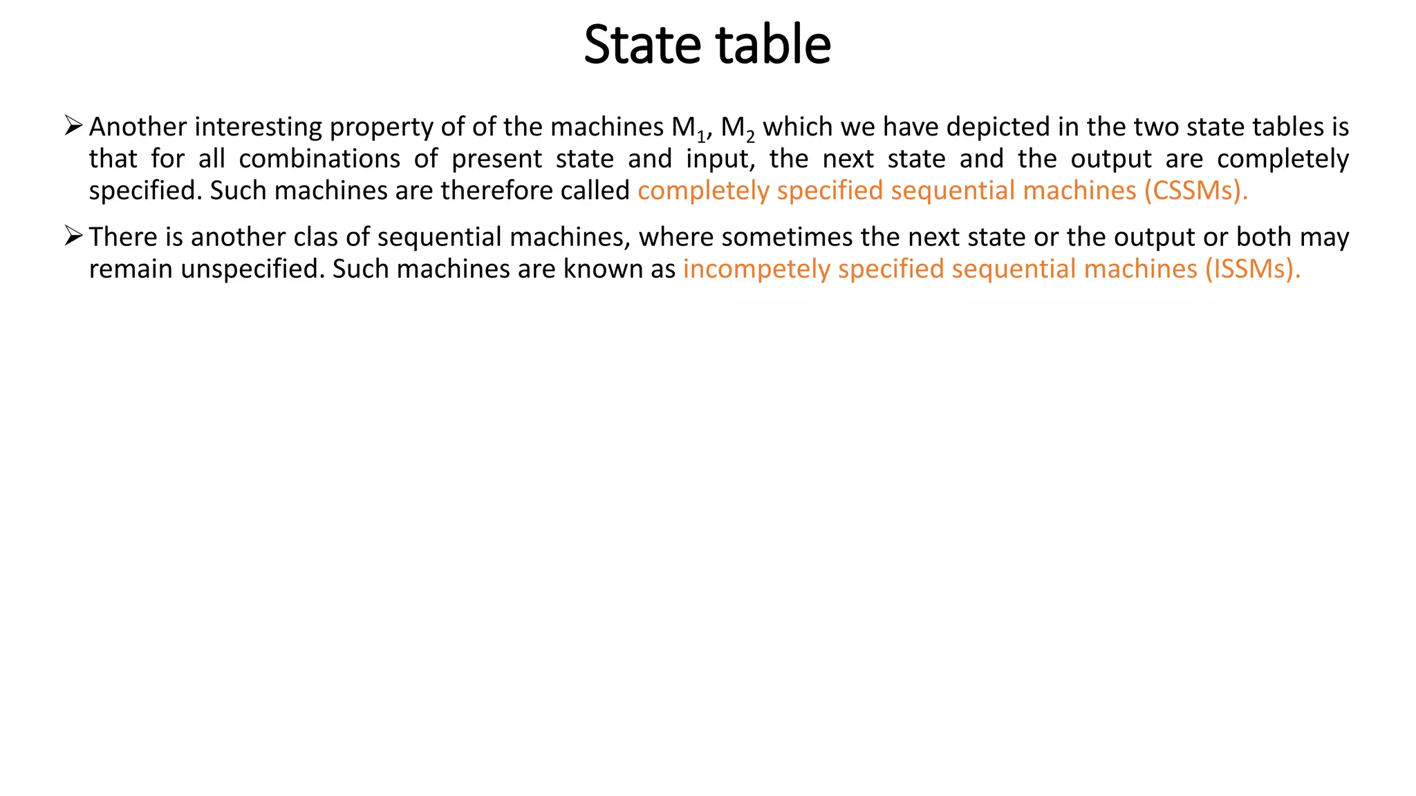
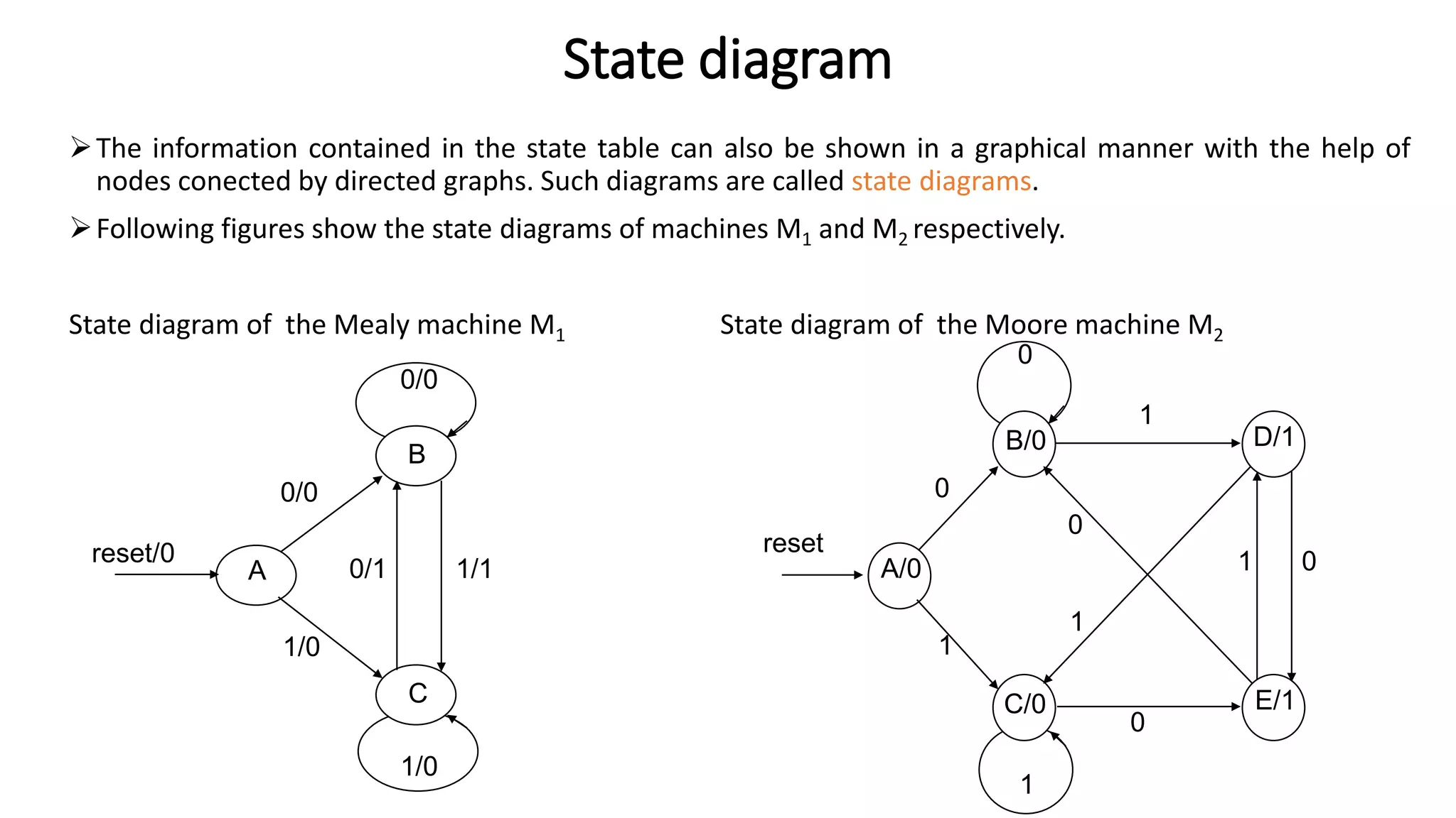
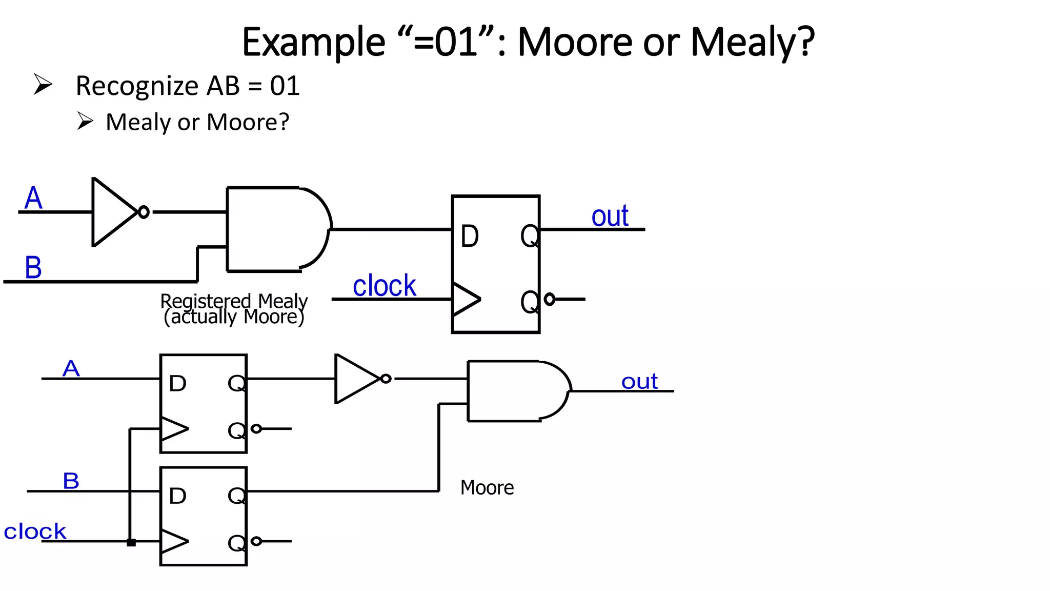
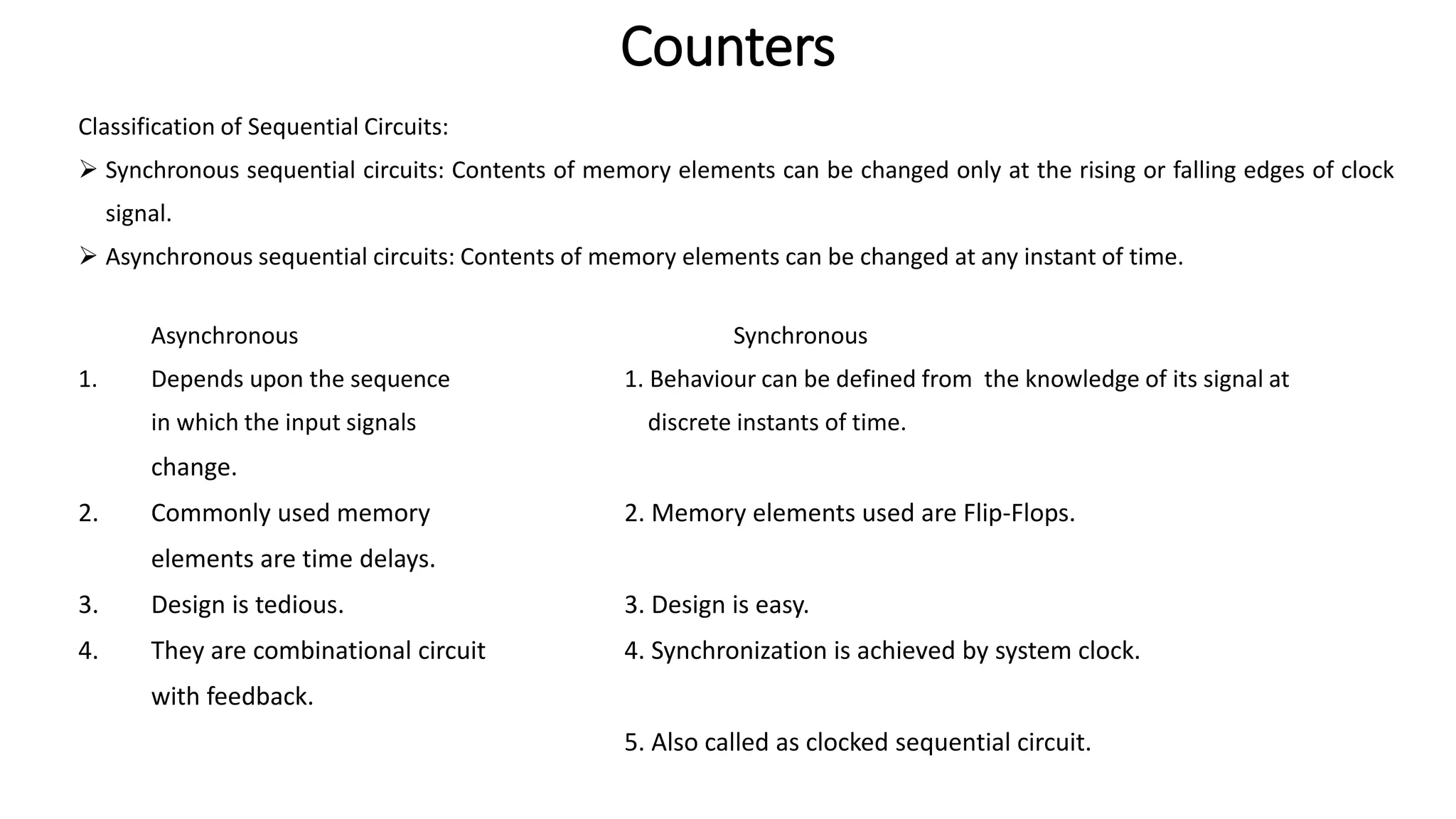
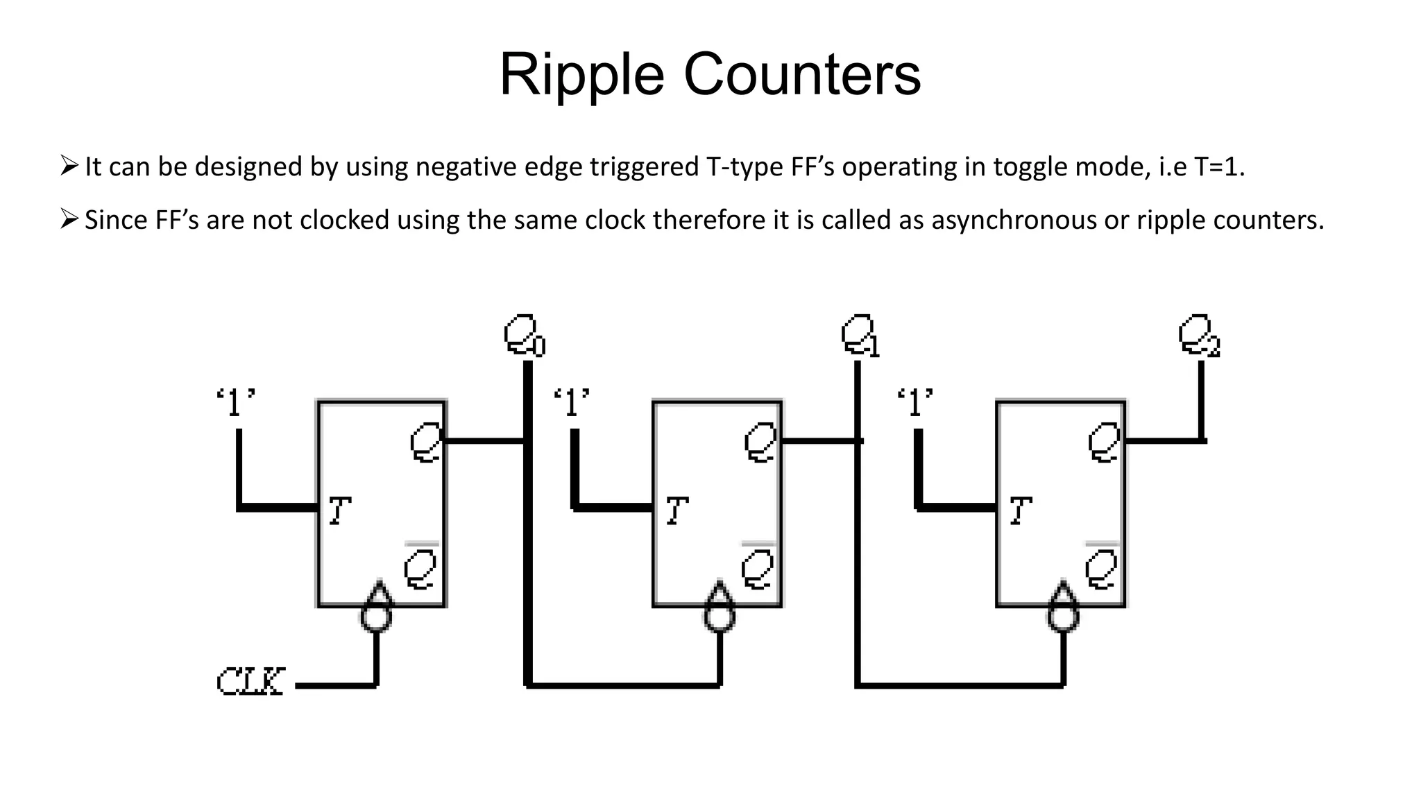
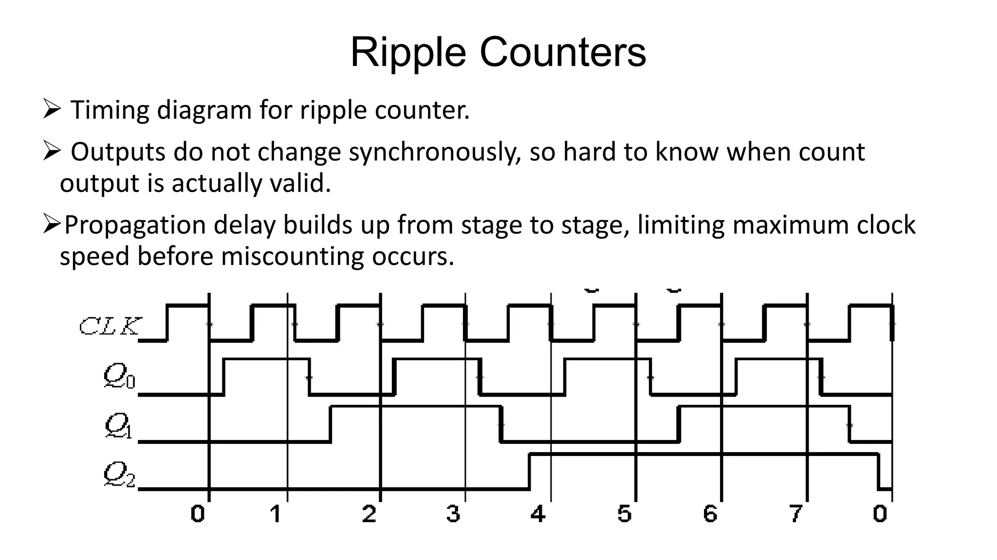
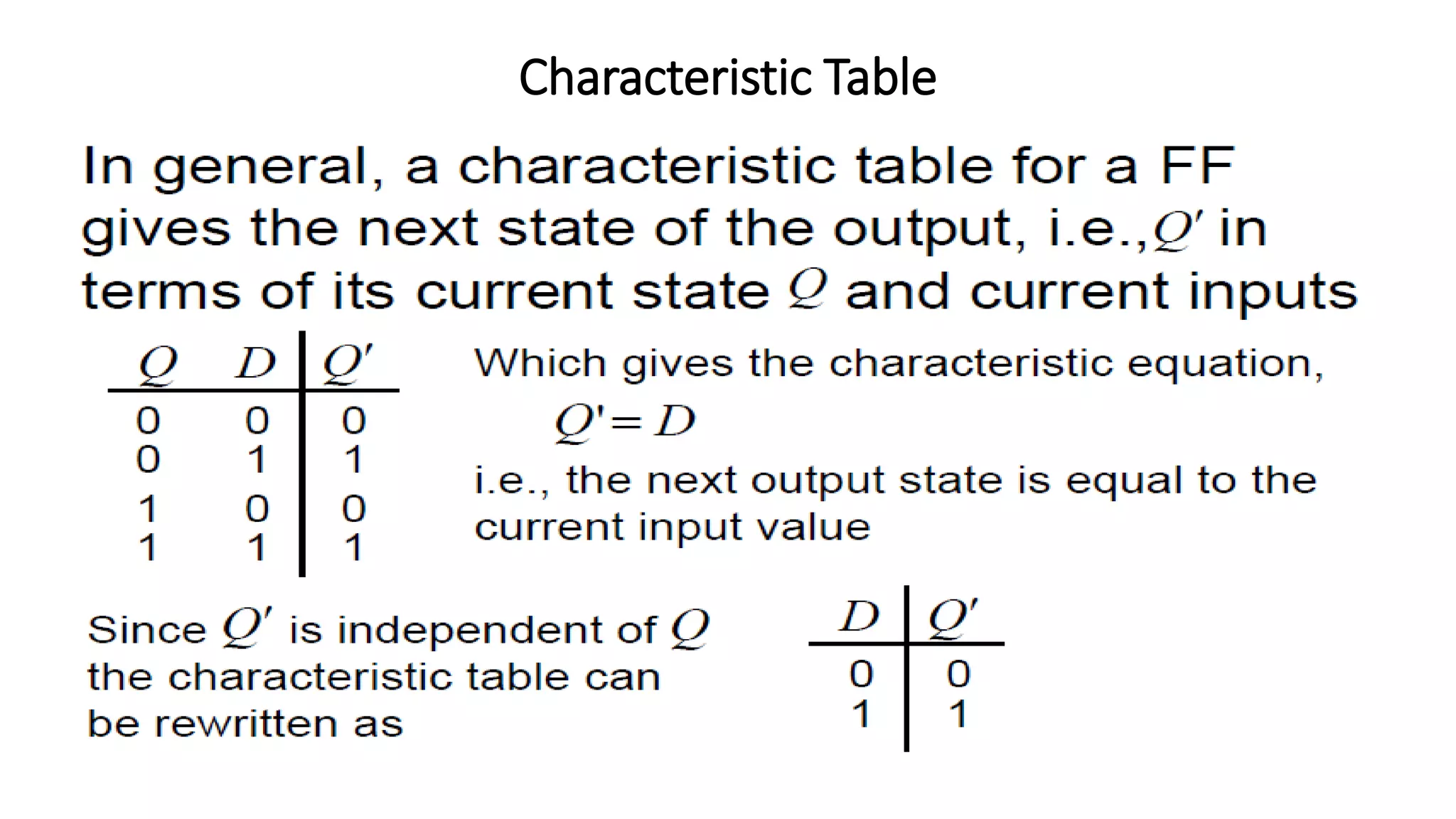
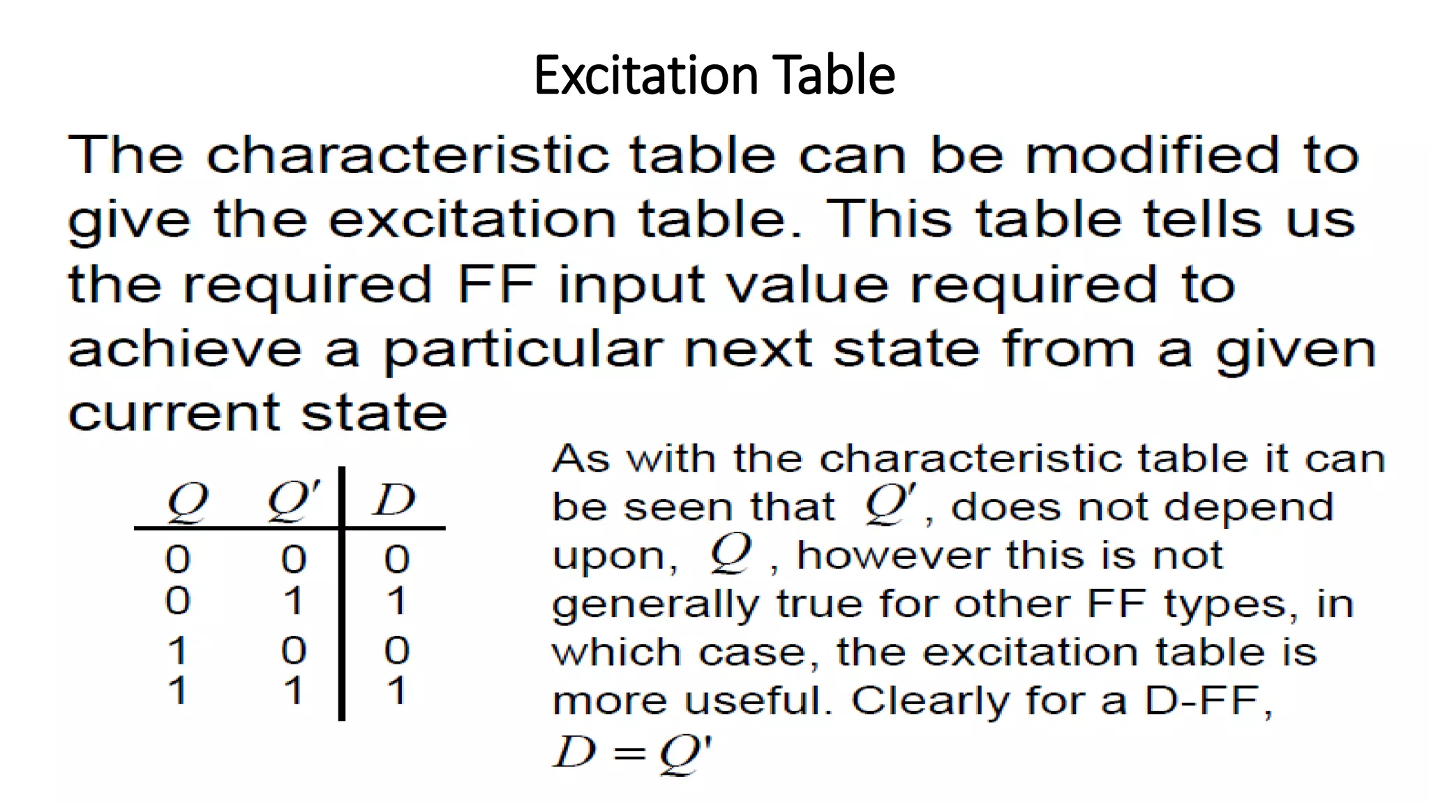
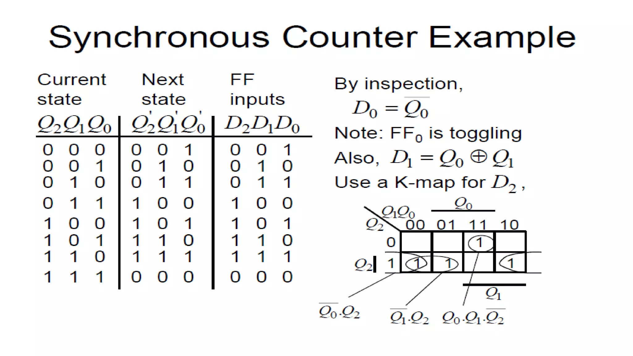
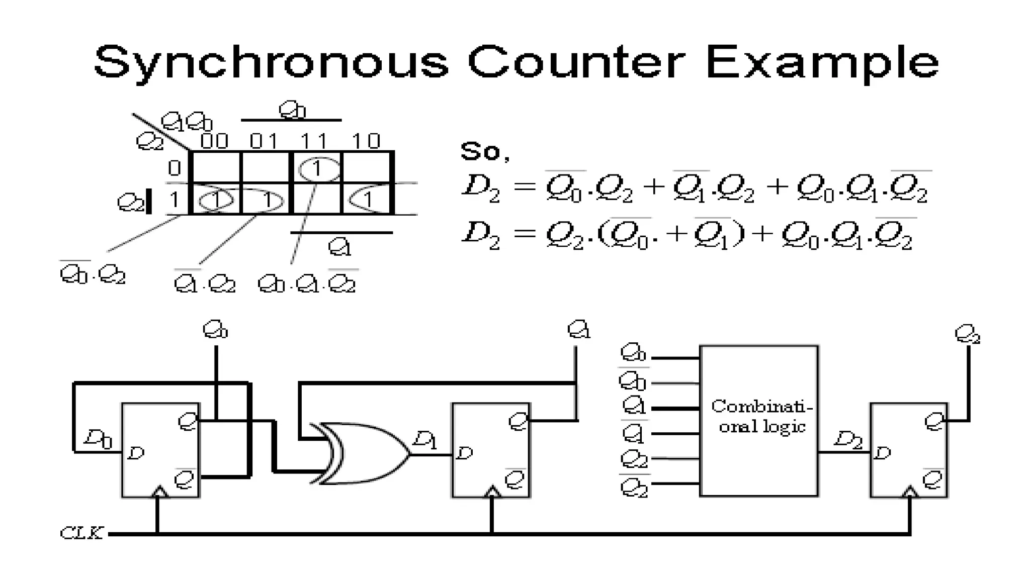
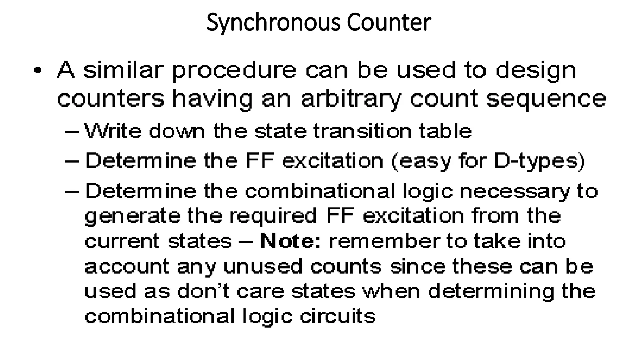
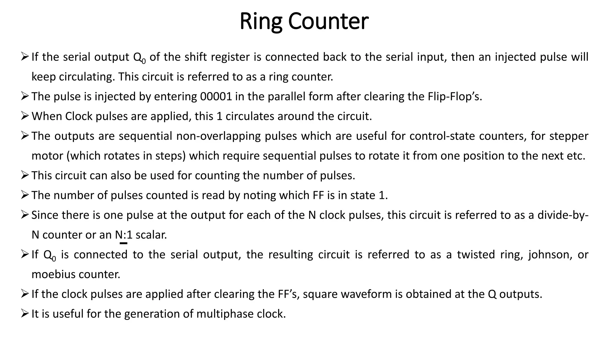
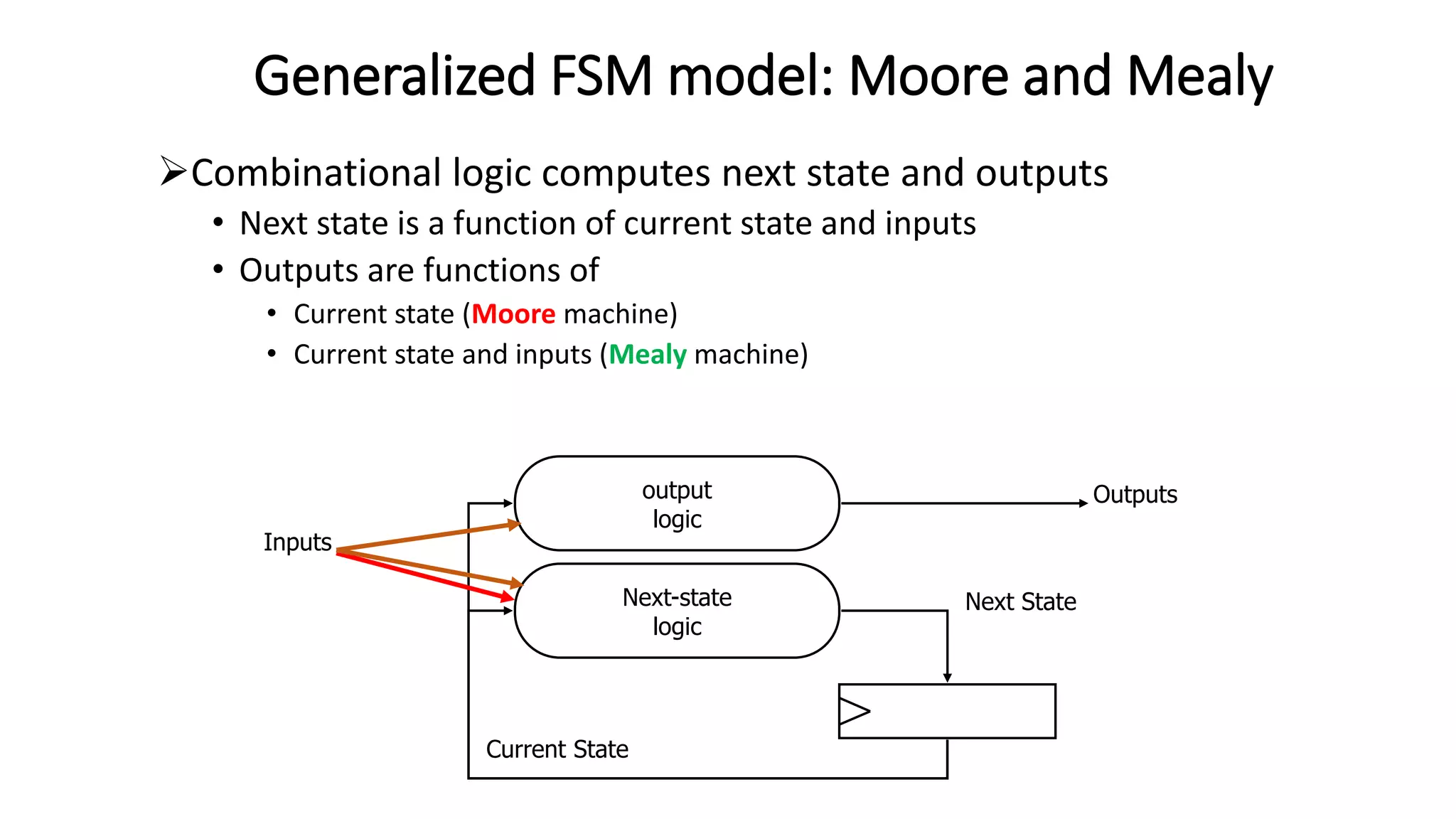
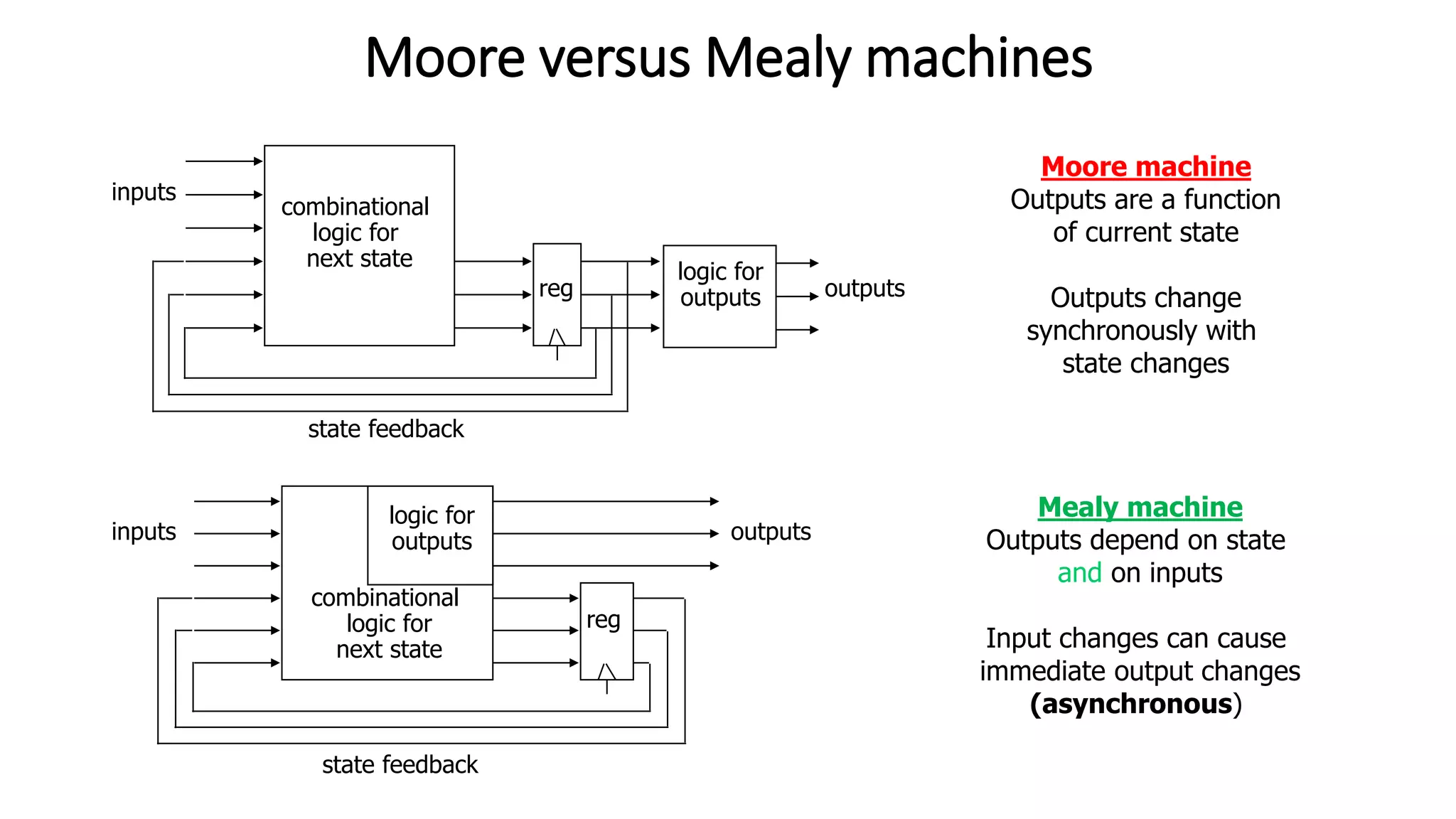
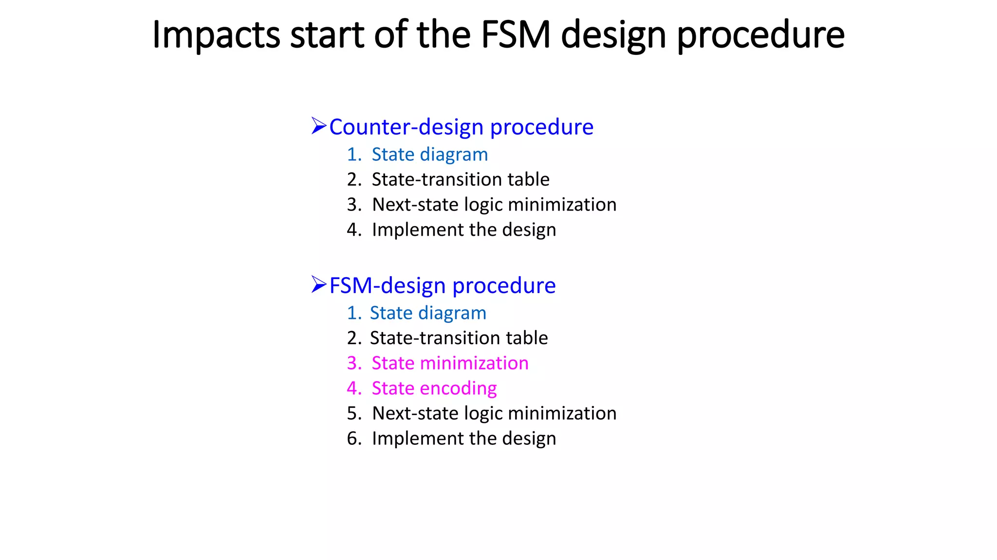
This document discusses various types of counters including asynchronous (ripple) counters and synchronous counters. It describes the basic operation and characteristics of ripple counters, synchronous counters, ring counters, Johnson counters, and modulus counters. It also covers the differences between synchronous and asynchronous sequential circuits. Finally, it provides information on finite state machines, including the differences between Moore and Mealy machines.
This document discusses asynchronous and synchronous counters. It provides examples of MOD-4, MOD-8, and MOD-6 asynchronous up counters using D flip-flops. It explains how synchronous counters use a common clock signal for all flip-flops. Examples are given for designing MOD-4 and MOD-4 synchronous up and down counters using JK flip-flops. The document also discusses asynchronous counter ICs and provides examples of MOD counters greater than a power of 2, such as MOD-9 and MOD-10, using T flip-flops.
This document discusses shift registers, which are digital circuits used to store and transfer data. A shift register consists of flip-flops connected in a linear fashion so that data is shifted from one flip-flop to the next on each clock cycle. Shift registers can be configured for serial-in serial-out, serial-in parallel-out, parallel-in serial-out, or parallel-in parallel-out data transfer. Common applications include communications, temporary storage, and time delay devices. The document also provides examples of shift register implementations using MSI logic chips.
B sc cs i bo-de u-iii counters & registersRai University
The document discusses registers and counters in digital circuits. It explains that counters are used for timing, sequencing, and counting applications. There are two main types of counters: ripple counters where each flip-flop triggers the next in sequence, and synchronous counters where all flip-flops are triggered simultaneously by a common clock. Binary ripple and synchronous 4-bit counters are described in detail through diagrams and explanations of their working principles. Parallel versus serial data transmission is also briefly discussed.
This document provides information about different types of counters, including asynchronous counters, synchronous counters, MSI counters, and specific counter integrated circuits. It defines counters and describes their basic characteristics. It discusses asynchronous ripple counters and their timing. It provides examples of decade and binary counters. It describes synchronous counters and MSI counters like the 74LS163 4-bit synchronous counter. Finally, it provides truth tables, logic diagrams, and application information for common counter ICs like the 7490, 7492, 7493, and 74LS163.
DELD Unit IV ring and twisted ring counterKanchanPatil34
A 4 bit bidirectional shift register allows data to be shifted either left or right based on the control signal level. When the control signal is high, gates G1-G4 are enabled and data shifts right as each flip flop's output is passed to the next flip flop's input. When low, gates G5-G7 are enabled and data shifts left by each flip flop passing its output to the previous flip flop's input.
The document discusses synchronous and asynchronous counters. It begins by explaining the difference between synchronous and asynchronous counters. Asynchronous counters have the clock signal applied to only the first flip-flop, while synchronous counters have the clock applied to all flip-flops simultaneously. The document then discusses various types of counters like up counters, down counters, decade counters, and up-down counters. It provides circuit diagrams and timing diagrams to illustrate the operation of these counters. It also discusses using integrated circuits like the 74293 to implement asynchronous counters of different moduli. Finally, it notes some disadvantages of asynchronous counters and why synchronous counters are preferable.
This document discusses using integrated circuit counters. It describes objectives of learning how to design simple synchronous and asynchronous counters using MSI chips. Specific objectives include being able to state common counter chips, describe their control pins, and design counters based on their technical references. Examples are provided on wiring a 74293 chip to make MOD-16, MOD-10 and MOD-14 counters, as well as combining two 74293s to make a MOD-60 counter.
This document discusses different types of counters, including asynchronous and synchronous counters. Asynchronous counters use flip-flops that are not connected to a common clock, resulting in a "ripple" effect. Synchronous counters connect all flip-flops to the same clock and use combinational logic to generate the next state. Counters can be cascaded to achieve higher modulus by connecting the output of one counter to the input of the next. The document also provides an example of designing a synchronous BCD counter and cascading a mod-10 and mod-8 counter.
This document discusses registers and counters. It defines registers as memory devices that can store multiple bits of information using flip-flops. There are several types of registers discussed, including shift registers, parallel in-serial out shift registers, and serial in-parallel out shift registers. Counters are also defined as sequential circuits that count through a predefined sequence of states. Asynchronous and synchronous counters are described as the two main types.
Registers are memory elements that store binary words. Counters are registers that count clock pulses. There are different types of registers like buffer registers, shift registers, and controlled shift registers. Ripple counters count clock pulses using JK flip flops but have propagation delays. Synchronous counters clock all flip flops simultaneously, eliminating propagation delays. Ring counters sequentially activate devices by having only one high bit in the stored word.
The attached narrated power point presentation reviews the construction, working and timing diagrams of ring and johnson counters as well as asynchronous and synchronous up, down, up/down and decade counters using popular flipflop ICs. The material will be useful for KTU B Tech second year students who prepare for the subject CSL 202, Digital Laboratory.
The document describes the steps to design a synchronous counter using sequential logic circuits. It begins with defining the learning outcomes as being able to design a counter through 7 steps: 1) state diagram, 2) next-state table, 3) flip-flop transition table, 4) circuit excitation table, 5) Karnaugh maps, 6) logic expressions, and 7) implementation. It then provides examples working through each step to design a 3-bit Gray code counter using J-K flip-flops. Exercises are provided to design additional counters.
This document discusses timers and interrupts on the ATmega328 microcontroller. It describes the digital I/O pins and functions for controlling them. It then covers the different types of interrupts including external interrupts from pins and pin change interrupts. The rest of the document details the timer/counter units 0, 1, and 2, including their registers, modes, and how to configure interrupts from timer events.
1. A counter is a sequential logic circuit consisting of a set of flip-flops which can go through a sequence of states.
2. There are two main types of counters - asynchronous counters and synchronous counters. Asynchronous counters have propagation delay issues and synchronous counters do not.
3. Counters can be designed to count up, down, or in other sequences depending on the state transition logic and excitation table used to determine the flip-flop inputs.
This document discusses interrupts in the 8051 microcontroller. It explains that interrupts allow a microcontroller to serve multiple devices by interrupting its main program flow to service higher priority requests, unlike polling which wastes time monitoring inactive devices. When an interrupt occurs, the microcontroller saves context and jumps to an interrupt service routine (ISR) located via an interrupt vector table. The 8051 has interrupts for timers, serial communication, and external pins which are enabled via the interrupt enable register and prioritized using the interrupt priority register.
Shift registers are digital circuits composed of flip-flops that can shift data from one stage to the next. They can be configured for serial-in serial-out, serial-in parallel-out, parallel-in serial-out, or parallel-in parallel-out data movement. Common applications include converting between serial and parallel data, temporary data storage, and implementing counters. MSI shift registers like the 74LS164 and 74LS166 provide 8-bit shift register functionality.
This document discusses different types of counters. It begins by classifying counters as either asynchronous (ripple) or synchronous. It then describes binary, decimal, octal and special counters based on their counting sequences. The document provides examples of 3-bit asynchronous and synchronous up/down counters. It explains how to create divide-by-N counters using MOD-N ripple counters. BCD ripple counters and 3-decade decimal counters are also illustrated. Finally, the timing and operation of synchronous counters is examined along with synchronous down and up/down counters.
A 3-bit synchronous down counter uses 3 negative edge triggered T flip-flops connected in series to count from 7 to 0 on each clock pulse. The T input of the first flip-flop is 1, while the T inputs of the second and third flip-flops are connected to the inverted outputs of the previous flip-flops. All flip-flops change state synchronously on the negative edge of the clock signal, allowing the counter to decrement in unison on each clock cycle.
Registers are groups of flip-flops that store binary data. Shift registers can transfer data in serial or parallel formats. There are four basic modes of shift registers: serial-in serial-out, serial-in parallel-out, parallel-in serial-out, and parallel-in parallel-out. Counters are circuits made of flip-flops that count clock pulses and can be asynchronous, synchronous, decade, up/down, or cascaded to achieve different counts.
A shift register is a digital circuit that can store and move data. It consists of flip-flops connected in a linear fashion so that data is shifted from one flip-flop to the next on each clock cycle. Shift registers have applications in converting between serial and parallel data, temporary storage, some arithmetic operations, communications, and counting. They can shift data in or out serially or parallel and either left or right depending on the type of shift register.
Counters are digital circuits that increment or decrement a stored value in response to a clock or trigger signal. There are two main types: ripple counters where the output of one flip-flop triggers the next, causing a ripple effect; and synchronous counters where all flip-flops change simultaneously according to a clock. Counters are widely used in computers and devices like clocks to keep track of events.
This document describes a binary up/down counter using the IC74193 chip. It includes the components needed, a description and pin diagram of the IC74193, simulations of count up and down operations, procedures for testing count up and down using switches and LED outputs, and schematic diagrams and applications of the counter circuit.
Synchronous counters use a common clock signal to toggle all flip-flops simultaneously, preventing propagation delay issues seen in asynchronous counters. A synchronous mod-10 (decimal) counter can be built from binary counters by adding logic to reset the count to 0 after reaching 10. This is achieved by detecting the 1001 state and toggling an additional flip-flop on the next clock pulse. Synchronous counters are used in applications like machine motion control and RPM measurement but require more components and complex circuitry compared to asynchronous counters.
A shift register is a digital circuit that can store and move data. It consists of flip-flops connected in a linear fashion so that data is shifted from one flip-flop to the next on each clock cycle. Shift registers can move data serially in or out, or in parallel, and are used for applications like serial-parallel conversion, temporary storage, arithmetic operations, communications, and counting.
Counters:
Introduction, Asynchronous counter, Terms related to counters, IC-7493 (4-bit binary counter), Synchronous counter, Bushing, Type T-Design, Type JK Design, Presettable counter, IC-7490, IC 7492, Synchronous counter ICs, Analysis of counter circuits
Presentation on Counters for (Digital Systems Design).pptxAniruddh70
1. Counters are sequential circuits that cycle through a sequence of states upon receiving a clock pulse or other input signal. They are used for applications like counting events, generating timing sequences, and addressing memory.
2. There are two main types of counters: asynchronous/ripple counters where each flip-flop is triggered by the previous one, and synchronous counters where all flip-flops are triggered simultaneously by a clock. Asynchronous counters are simpler but slower while synchronous counters are faster but more complex.
3. Binary counters follow a binary sequence and can count from 0 to 2n-1 for an n-bit counter. Other counter types include up/down, ring, Johnson, and decade counters.
Digital Logic Design (EEEg4302)
Chapter 7 : Counters
This chapter discusses different types of counters, including asynchronous (ripple) counters and synchronous counters. Asynchronous counters use a ripple effect where one flip-flop triggers the next. Synchronous counters use a common clock signal to trigger all flip-flops simultaneously. The chapter also covers up/down counters, which can count up or down based on control signals, and methods for designing synchronous counters through state diagrams and logic expressions.
This document provides an overview of sequential circuits and flip-flops. It discusses the basic components and operation of flip-flops including triggering, excitation tables, and different types of flip-flops. Applications of flip-flops like counters, shift registers, and their design procedures are also covered. Shift registers are described in detail including their types and applications such as time delays and serial-parallel data conversion.
Latches
– Flip-Flops - SR, JK, D and T
– Master Slave Flip Flops
• Shift Registers
– SISO, SIPO, PISO, PIPO and Universal
• Binary Counters
– Synchronous and asynchronous up/down counters
– mod - N counter
– Counters for random sequence
– Johnson counter and Ring counter
This document discusses counters, which are digital circuits used for counting pulses. It describes asynchronous and synchronous counters, and different types including up/down counters, decade counters, ring counters, and Johnson counters. Examples of counter applications are given such as in kitchen appliances, washing machines, microwaves, and programmable logic controllers. Counters are used for tasks like time measurement, frequency division, and digital signal generation.
The document provides an overview of various types of shift registers and counters. It describes serial-in serial-out, serial-in parallel-out, parallel-in serial-out, and parallel-in parallel-out shift registers. It explains how each type handles data input and output and the number of clock cycles needed for loading and reading. It also covers asynchronous and synchronous counters such as ripple counters and how they differ in clocking approach. Bidirectional shift registers are described as able to shift data either left or right depending on the mode.
The document discusses synchronous and asynchronous counters. It defines a counter as a digital circuit that counts input pulses. Asynchronous counters have flip-flops that change state at different times since they do not share a common clock. Synchronous counters have all flip-flops change simultaneously due to a shared global clock, allowing them to operate at higher frequencies. The document provides examples of 2-bit, 3-bit, and 4-bit synchronous binary counters as well as a 4-bit synchronous decade counter along with their operations and timing diagrams.
EC8392 Digital Electronics- Unit-3 -S.Sesha Vidhya-ASP-ECE-RMKCETSeshaVidhyaS
This document discusses synchronous sequential circuits and various types of flip-flops and counters. It begins with definitions of synchronous circuits and differences between latches and flip-flops. It then explains the operation of common flip-flop types including SR, D, JK, and T flip-flops. Next, it covers analysis and design of clocked sequential circuits using Moore and Mealy models. Finally, it discusses various counter types such as ripple, ring, and shift registers with examples.
This document discusses counters and their applications. It begins by defining a counter as a sequential digital device used for counting up or down. There are different types of counters including asynchronous (ripple) counters and binary counters. Counters are used for applications like frequency division and reducing the frequency of a clock signal. Flip-flops are also discussed as they are the basic building blocks of counters. Specific counter circuits like binary ripple counters, BCD counters, and techniques for designing counters with modular values other than powers of two are described.
This document discusses different types of counters used in digital circuits. It defines a counter as a sequential circuit that cycles through a sequence of states in response to clock pulses. Binary counters count in binary and can count from 0 to 2n-1 with n flip-flops. Asynchronous counters have flip-flops that are not triggered simultaneously by a clock, while synchronous counters use a common clock for all flip-flops. Other counter types include ring counters, Johnson counters, and decade counters. The document provides examples of binary, asynchronous, and synchronous counters and discusses their applications in areas like timing sequences and addressing memory.
Digital Fundamental Material for the studentjainyshah20
The document discusses sequential switching circuits and various types of flip-flops and counters. It provides details on S-R, J-K, D and T flip-flops. Applications of flip-flops include parallel and serial data storage, counting, frequency division. Registers are groups of flip-flops used to store multiple bits of data. Shift registers allow serial or parallel data input/output. Asynchronous counters use flip-flops connected in a ripple fashion while synchronous counters clock all flip-flops simultaneously. Examples of 2-bit asynchronous up/down and ring counters are shown.
1. The document discusses different types of registers, counters, and shift registers including their components, functions, and loading/shifting processes.
2. It also covers synchronous and asynchronous counters as well as ring and Johnson counters.
3. Finally, it discusses integrated circuits and different digital logic families including TTL, ECL, MOS, CMOS, and I2L.
This document summarizes a presentation about digital counters. It discusses different types of counters including asynchronous and synchronous counters. Asynchronous counters have the clock pulse applied to the first flip-flop, while successive flip-flops are triggered by the output of the previous one, resulting in cumulative settling time. Synchronous counters have all flip-flop clock inputs connected together and triggered simultaneously by input pulses. The document provides truth tables and examples of asynchronous and synchronous counter circuit designs using JK flip-flops. It concludes with a thank you for the presentation.
There are several types of counters that can be implemented using flip-flops and logic gates. Asynchronous/ripple counters use the output of one flip-flop as the clock input for the next flip-flop, resulting in the clock pulse "ripping" through the chain. Synchronous counters clock all flip-flops simultaneously using a single clock. Decade counters count to 10 before resetting. Shift register counters like ring counters and Johnson counters produce specific output sequences by feeding the output back as the input.
Introduction to flipflops basic of elctronics COA.pptxSaini71
The document discusses different types of digital circuits, including combinational circuits and sequential circuits. It focuses on sequential circuits and describes them as circuits that store and use previous state information. The document discusses two types of sequential circuits - asynchronous and synchronous. It also discusses different types of memory elements used in sequential circuits, including latches and flip-flops. Specifically, it describes SR latches, D latches, and different types of flip-flops like SR, JK, D and T flip-flops. It provides truth tables and diagrams to explain the working of these memory elements.
The document summarizes different types of digital counters, including asynchronous counters, synchronous counters, ring counters, and Johnson counters. Asynchronous counters have each flip-flop triggered by the previous one, limiting speed, while synchronous counters trigger all flip-flops simultaneously using a common clock, increasing speed. Ring counters circulate a single '1' bit around the register. Johnson counters are like ring counters but with the inverted output of the last flip-flop connected to the first. Examples and applications of each type are provided.
The document discusses different types of shift registers and counters. It describes serial-in serial-out, serial-in parallel-out, parallel-in serial-out, and parallel-in parallel-out shift registers. It also covers asynchronous and synchronous counters such as ripple counters, up/down counters, and mod-N counters. Diagrams and truth tables are provided to illustrate the working of different shift registers and counters.
VARIABLE FREQUENCY DRIVE. VFDs are widely used in industrial applications for...PIMR BHOPAL
Variable frequency drive .A Variable Frequency Drive (VFD) is an electronic device used to control the speed and torque of an electric motor by varying the frequency and voltage of its power supply. VFDs are widely used in industrial applications for motor control, providing significant energy savings and precise motor operation.
Generative AI Use cases applications solutions and implementation.pdfmahaffeycheryld
Generative AI solutions encompass a range of capabilities from content creation to complex problem-solving across industries. Implementing generative AI involves identifying specific business needs, developing tailored AI models using techniques like GANs and VAEs, and integrating these models into existing workflows. Data quality and continuous model refinement are crucial for effective implementation. Businesses must also consider ethical implications and ensure transparency in AI decision-making. Generative AI's implementation aims to enhance efficiency, creativity, and innovation by leveraging autonomous generation and sophisticated learning algorithms to meet diverse business challenges.
https://www.leewayhertz.com/generative-ai-use-cases-and-applications/
Applications of artificial Intelligence in Mechanical Engineering.pdfAtif Razi
Historically, mechanical engineering has relied heavily on human expertise and empirical methods to solve complex problems. With the introduction of computer-aided design (CAD) and finite element analysis (FEA), the field took its first steps towards digitization. These tools allowed engineers to simulate and analyze mechanical systems with greater accuracy and efficiency. However, the sheer volume of data generated by modern engineering systems and the increasing complexity of these systems have necessitated more advanced analytical tools, paving the way for AI.
AI offers the capability to process vast amounts of data, identify patterns, and make predictions with a level of speed and accuracy unattainable by traditional methods. This has profound implications for mechanical engineering, enabling more efficient design processes, predictive maintenance strategies, and optimized manufacturing operations. AI-driven tools can learn from historical data, adapt to new information, and continuously improve their performance, making them invaluable in tackling the multifaceted challenges of modern mechanical engineering.
Design and optimization of ion propulsion dronebjmsejournal
Electric propulsion technology is widely used in many kinds of vehicles in recent years, and aircrafts are no exception. Technically, UAVs are electrically propelled but tend to produce a significant amount of noise and vibrations. Ion propulsion technology for drones is a potential solution to this problem. Ion propulsion technology is proven to be feasible in the earth’s atmosphere. The study presented in this article shows the design of EHD thrusters and power supply for ion propulsion drones along with performance optimization of high-voltage power supply for endurance in earth’s atmosphere.
Electric vehicle and photovoltaic advanced roles in enhancing the financial p...IJECEIAES
Climate change's impact on the planet forced the United Nations and governments to promote green energies and electric transportation. The deployments of photovoltaic (PV) and electric vehicle (EV) systems gained stronger momentum due to their numerous advantages over fossil fuel types. The advantages go beyond sustainability to reach financial support and stability. The work in this paper introduces the hybrid system between PV and EV to support industrial and commercial plants. This paper covers the theoretical framework of the proposed hybrid system including the required equation to complete the cost analysis when PV and EV are present. In addition, the proposed design diagram which sets the priorities and requirements of the system is presented. The proposed approach allows setup to advance their power stability, especially during power outages. The presented information supports researchers and plant owners to complete the necessary analysis while promoting the deployment of clean energy. The result of a case study that represents a dairy milk farmer supports the theoretical works and highlights its advanced benefits to existing plants. The short return on investment of the proposed approach supports the paper's novelty approach for the sustainable electrical system. In addition, the proposed system allows for an isolated power setup without the need for a transmission line which enhances the safety of the electrical network
Digital Twins Computer Networking Paper Presentation.pptxaryanpankaj78
A Digital Twin in computer networking is a virtual representation of a physical network, used to simulate, analyze, and optimize network performance and reliability. It leverages real-time data to enhance network management, predict issues, and improve decision-making processes.
Optimizing Gradle Builds - Gradle DPE Tour Berlin 2024Sinan KOZAK
Sinan from the Delivery Hero mobile infrastructure engineering team shares a deep dive into performance acceleration with Gradle build cache optimizations. Sinan shares their journey into solving complex build-cache problems that affect Gradle builds. By understanding the challenges and solutions found in our journey, we aim to demonstrate the possibilities for faster builds. The case study reveals how overlapping outputs and cache misconfigurations led to significant increases in build times, especially as the project scaled up with numerous modules using Paparazzi tests. The journey from diagnosing to defeating cache issues offers invaluable lessons on maintaining cache integrity without sacrificing functionality.
Null Bangalore | Pentesters Approach to AWS IAMDivyanshu
#Abstract:
- Learn more about the real-world methods for auditing AWS IAM (Identity and Access Management) as a pentester. So let us proceed with a brief discussion of IAM as well as some typical misconfigurations and their potential exploits in order to reinforce the understanding of IAM security best practices.
- Gain actionable insights into AWS IAM policies and roles, using hands on approach.
#Prerequisites:
- Basic understanding of AWS services and architecture
- Familiarity with cloud security concepts
- Experience using the AWS Management Console or AWS CLI.
- For hands on lab create account on [killercoda.com](https://killercoda.com/cloudsecurity-scenario/)
# Scenario Covered:
- Basics of IAM in AWS
- Implementing IAM Policies with Least Privilege to Manage S3 Bucket
- Objective: Create an S3 bucket with least privilege IAM policy and validate access.
- Steps:
- Create S3 bucket.
- Attach least privilege policy to IAM user.
- Validate access.
- Exploiting IAM PassRole Misconfiguration
-Allows a user to pass a specific IAM role to an AWS service (ec2), typically used for service access delegation. Then exploit PassRole Misconfiguration granting unauthorized access to sensitive resources.
- Objective: Demonstrate how a PassRole misconfiguration can grant unauthorized access.
- Steps:
- Allow user to pass IAM role to EC2.
- Exploit misconfiguration for unauthorized access.
- Access sensitive resources.
- Exploiting IAM AssumeRole Misconfiguration with Overly Permissive Role
- An overly permissive IAM role configuration can lead to privilege escalation by creating a role with administrative privileges and allow a user to assume this role.
- Objective: Show how overly permissive IAM roles can lead to privilege escalation.
- Steps:
- Create role with administrative privileges.
- Allow user to assume the role.
- Perform administrative actions.
- Differentiation between PassRole vs AssumeRole
Try at [killercoda.com](https://killercoda.com/cloudsecurity-scenario/)
Redefining brain tumor segmentation: a cutting-edge convolutional neural netw...IJECEIAES
Medical image analysis has witnessed significant advancements with deep learning techniques. In the domain of brain tumor segmentation, the ability to
precisely delineate tumor boundaries from magnetic resonance imaging (MRI)
scans holds profound implications for diagnosis. This study presents an ensemble convolutional neural network (CNN) with transfer learning, integrating
the state-of-the-art Deeplabv3+ architecture with the ResNet18 backbone. The
model is rigorously trained and evaluated, exhibiting remarkable performance
metrics, including an impressive global accuracy of 99.286%, a high-class accuracy of 82.191%, a mean intersection over union (IoU) of 79.900%, a weighted
IoU of 98.620%, and a Boundary F1 (BF) score of 83.303%. Notably, a detailed comparative analysis with existing methods showcases the superiority of
our proposed model. These findings underscore the model’s competence in precise brain tumor localization, underscoring its potential to revolutionize medical
image analysis and enhance healthcare outcomes. This research paves the way
for future exploration and optimization of advanced CNN models in medical
imaging, emphasizing addressing false positives and resource efficiency.
Rainfall intensity duration frequency curve statistical analysis and modeling...bijceesjournal
Using data from 41 years in Patna’ India’ the study’s goal is to analyze the trends of how often it rains on a weekly, seasonal, and annual basis (1981−2020). First, utilizing the intensity-duration-frequency (IDF) curve and the relationship by statistically analyzing rainfall’ the historical rainfall data set for Patna’ India’ during a 41 year period (1981−2020), was evaluated for its quality. Changes in the hydrologic cycle as a result of increased greenhouse gas emissions are expected to induce variations in the intensity, length, and frequency of precipitation events. One strategy to lessen vulnerability is to quantify probable changes and adapt to them. Techniques such as log-normal, normal, and Gumbel are used (EV-I). Distributions were created with durations of 1, 2, 3, 6, and 24 h and return times of 2, 5, 10, 25, and 100 years. There were also mathematical correlations discovered between rainfall and recurrence interval.
Findings: Based on findings, the Gumbel approach produced the highest intensity values, whereas the other approaches produced values that were close to each other. The data indicates that 461.9 mm of rain fell during the monsoon season’s 301st week. However, it was found that the 29th week had the greatest average rainfall, 92.6 mm. With 952.6 mm on average, the monsoon season saw the highest rainfall. Calculations revealed that the yearly rainfall averaged 1171.1 mm. Using Weibull’s method, the study was subsequently expanded to examine rainfall distribution at different recurrence intervals of 2, 5, 10, and 25 years. Rainfall and recurrence interval mathematical correlations were also developed. Further regression analysis revealed that short wave irrigation, wind direction, wind speed, pressure, relative humidity, and temperature all had a substantial influence on rainfall.
Originality and value: The results of the rainfall IDF curves can provide useful information to policymakers in making appropriate decisions in managing and minimizing floods in the study area.
3. Counters
➢Counters: Asynchronous counter. Synchronous counter, ring counters, Johnson Counter,
Modulus of the counter (IC 7490).
➢Synchronous Sequential Circuit Design: Models – Moore and Mealy, State diagram and State
Tables, Design Procedure, Sequence generator and detector.
➢Asynchronous Sequential Circuit Design: Difference with synchronous circuit design, design
principles and procedure, applications.
4. Counters
➢There are two types of counters Asynchronous (ripple) & Synchronous counters.
➢Asynchronous counter is easy to design & requires the least amount of homework.
➢Asynchronous counter is not triggered simultaneously & is also called as serial or series counter.
➢Design of Synchronous counter requires some amount of homework & each Flip-Flop is triggered
simultaneously.
➢Each count of the counter is called as a state of the counter.
➢The number of states through which the counter passes before returning to the starting state is called
the modulus of the counter.
➢E.g. A 2-bit counter has 4 states, it is called a mod-4 counter & as it divides the clock signal frequency
by 4, it is called as divide-by-4 counter.
➢An n-bit counter will have n FF’s & 2n states, and divides the input frequency by 2n. Hence it is called as
divide-by-2n counter. The LSB of ripple counters is the Q output of the FF to which the external clock is
applied.
5. Counters
Classification of Sequential Circuits:
➢ Synchronous sequential circuits: Contents of memory elements can be changed only at the rising or falling edges of clock
signal.
➢ Asynchronous sequential circuits: Contents of memory elements can be changed at any instant of time.
Asynchronous Synchronous
1. Depends upon the sequence 1. Behaviour can be defined from the knowledge of its signal at
in which the input signals discrete instants of time.
change.
2. Commonly used memory 2. Memory elements used are Flip-Flops.
elements are time delays.
3. Design is tedious. 3. Design is easy.
4. They are combinational circuit 4. Synchronization is achieved by system clock.
with feedback.
5. Also called as clocked sequential circuit.
6. ➢It is common for the FF types we have mentioned to also have additional so called ‘asynchronous’ inputs
➢They are called asynchronous since they take effect independently of any clock or enable inputs.
➢Reset/Clear – force Q to 0
➢Preset/Set – force Q to 1
➢Often used to force a synchronous circuit into a known state, say at start-up.
Asynchronous Inputs
7. Ripple Counters
➢It can be designed by using negative edge triggered T-type FF’s operating in toggle mode, i.e T=1.
➢Since FF’s are not clocked using the same clock therefore it is called as asynchronous or ripple counters.
8. Ripple Counters
➢ Timing diagram for ripple counter.
➢ Outputs do not change synchronously, so hard to know when count
output is actually valid.
➢Propagation delay builds up from stage to stage, limiting maximum clock
speed before miscounting occurs.
9. Synchronous Counters
➢All flip flop clock inputs are directly connected to the clock signal and so all FF outputs change at the
same time, i.e. synchronously.
➢More complex combinational logic is now needed to generate the appropriate FF input signals(Which will
be different depending upon the type of FF chosen.)
➢We can design synchronous counters using any type of Flip-Flops.
➢We will consider using D-type FFs to design 0-7 up counter.
➢ While designing counter we will make use of a modified state transition table. This table has additional
columns that defines the required FF inputs(or excitation table values).
➢We make use of excitation table for a particular type of FF.
➢Firstly investigate the so called characteristic table and characteristic equation for a FF.
➢For D-FFs it is not necessary to write out the FF input columns, since we know they are identical to those
for the next state.
➢To design the circuit we need to determine appropriate combinational logic circuits which will generate
the required FF inputs from the current states.
➢This can be done using Boolean algebra or using K-maps.
19. Ring Counter
➢If the serial output Q0 of the shift register is connected back to the serial input, then an injected pulse will
keep circulating. This circuit is referred to as a ring counter.
➢The pulse is injected by entering 00001 in the parallel form after clearing the Flip-Flop’s.
➢When Clock pulses are applied, this 1 circulates around the circuit.
➢The outputs are sequential non-overlapping pulses which are useful for control-state counters, for stepper
motor (which rotates in steps) which require sequential pulses to rotate it from one position to the next etc.
➢This circuit can also be used for counting the number of pulses.
➢The number of pulses counted is read by noting which FF is in state 1.
➢Since there is one pulse at the output for each of the N clock pulses, this circuit is referred to as a divide-by-
N counter or an N:1 scalar.
➢If Q0 is connected to the serial output, the resulting circuit is referred to as a twisted ring, johnson, or
moebius counter.
➢If the clock pulses are applied after clearing the FF’s, square waveform is obtained at the Q outputs.
➢It is useful for the generation of multiphase clock.
20. Ring Counter
➢Ring counters are constructed by modifying the serial-in, serial-out, shift registers. There are two types of
ring counters- basic ring counter & Johnson counter.
➢The basic ring counter can be obtained from a serial-in, serial-out, shift register by connecting Q output of
the last FF to D input of first FF.
➢The ring counter is the decimal counter. It is divide-by-N counter, where N is the number of stages. The
keyboard encoder is an application of a ring counter.
21. Twisted Ring Counter (Johnson Counter)
➢It is obtained from a serial-in, serial-out shift register by providing a feedback from Q bar of last FF to the
D input of first FF, called as twisted ring counter.
➢The output Q is connected to the D input of next stage.
➢It produces the unique sequence of states.
➢Initially all the FF’s are reset i.e. the state of counter is 0000.
➢After each clock pulse, the level of Q1 is shifted to Q2, the level of Q2 to Q3, Q3 to Q4 & finally Q4 bar to
Q1. The sequence is repeated after every 8 clock pulse.
➢N Flip-Flop or n-bit Johnson counter can have 2n unique states and can count up to 2n states. So it is mod-
2n counter.
22. Twisted Ring Counter (Johnson Counter)
Advantages:
1. It is more economical than ring counter but less than ripple counter.
Disadvantages:
1. It requires 2 input gates for decoding regardless of number of Flip-Flops.
2. Both the ring counters suffer from problem of lock out i.e. if the counter finds itself in an unused
state, it will persist in moving from one unused state to another and will never find its way to a used
state.
23. Modulus of the counter (IC 7490)
7490 Asynchronous Counter IC: (Modulus of the counter)
➢ IC’s available are divided into 3 groups A,B,C depending on its features. It consists of four MS-FF.
➢ The load, set & reset (clear) operations are asynchronous. i.e. independent of clock pulse.
➢ It consists of four FF’s internally connected to provide mod-2 counter & a mod-5 counter. These
counters can be used independently or in combination.
➢ FFA operates as a mod-2 counter whereas the combination of FFB, FFC & FFD form a mod-5 counter.
➢ The two reset inputs R1 & R2 both are connected to logic 1 level for clearing all FF’s.
➢ The two set inputs S1 & S2 when connected to logic 1 level, are used for setting the counter to 1001.
➢ E.g. In a 7490 if QA output is connected to B input and the pulses are applied at A input, find the count
sequence. Ans. It is a decade counter.
24. Generalized FSM model: Moore and Mealy
➢Combinational logic computes next state and outputs
• Next state is a function of current state and inputs
• Outputs are functions of
• Current state (Moore machine)
• Current state and inputs (Mealy machine)
Inputs
Outputs
Next State
Current State
output
logic
Next-state
logic
25. Moore and Mealy Machines
There are two types of finite state machine that can be built from sequential logic circuits:
➢Moore machine: The output depends only on the internal state. (Since the internal state only changes on a
clock edge, the output only changes on a clock edge).
➢Mealy Machine: The output depends not only on the internal state, but also on the inputs.
➢A clocked sequential system is a kind of Moore machine.
26. Moore versus Mealy machines
outputs
state feedback
inputs
reg
combinational
logic for
next state
logic for
outputs
Moore machine
Outputs are a function
of current state
Outputs change
synchronously with
state changes
Mealy machine
Outputs depend on state
and on inputs
Input changes can cause
immediate output changes
(asynchronous)
inputs outputs
state feedback
reg
combinational
logic for
next state
logic for
outputs
27. Impacts start of the FSM design procedure
➢Counter-design procedure
1. State diagram
2. State-transition table
3. Next-state logic minimization
4. Implement the design
➢FSM-design procedure
1. State diagram
2. State-transition table
3. State minimization
4. State encoding
5. Next-state logic minimization
6. Implement the design
28. State Diagrams
➢ Moore machine
• Each state is labeled by a pair:
state-name/output or state-name [output]
➢ Mealy machine
• Each transition arc is labeled by a pair:
input-condition/output
29. D Q
Q
D Q
Q
D Q
Q
D Q
Q
A
B
clock
out
D Q
Q
D Q
Q
A
B
clock
out
Example 10 → 01: Moore or Mealy?
• Circuits recognize AB=10 followed by AB=01
• What kinds of machines are they?
Moore
Mealy
30. Example “01 or 10” detector: a Moore machine
• Output is a function of state only
• Specify output in the state bubble
D/1
E/1
B/0
A/0
C/0
1
0
0
0
0
1
1
1
1
0
reset
current next current
reset input state state output
1 – – A 0
0 0 A B 0
0 1 A C 0
0 0 B B 0
0 1 B D 0
0 0 C E 0
0 1 C C 0
0 0 D E 1
0 1 D C 1
0 0 E B 1
0 1 E D 1
31. Example “01 or 10” detector: a Mealy machine
• Output is a function of state and inputs
• Specify outputs on transition arcs
current next current
reset input state state output
B
A
C
0/1
0/0
0/0
1/1
1/0
1/0
reset/0
1 – – A 0
0 0 A B 0
0 1 A C 0
0 0 B B 0
0 1 B C 1
0 0 C B 1
0 1 C C 0
34. Mealy and Moore Machine
In general, a sequential machine will have the following:
1. A set S containing a finite number, say p, of internal states, so that
S={S1, S2,……Sp}
2. A set X having a finite number, say n, of inputs, so that
X={X1, X2,……Xn}
3. A set Z containing a finite number, say m, of outputs, so that
Z={Z1, Z2,……Zm}
4. A characterizing function f that uniquely defines the next state St+1 as a function of the present state St and the
present input Xt , so that St+1 = f(St , Xt )
5.A) Mealy machine
A characterizing function g that uniquely defines the output Zt as a function of the present input Xt and the
present internal state St , so that
Zt = g(St , Xt )
5.B) Moore machine
A characterizing function g that uniquely defines the output Zt as a function of the present internal state St , so that
Zt = g(St )
35. Mealy and Moore Machine
A sequential machine can therefore formally be defined as follows:
Definition:A sequential machine is a quintuple,
M=(X,Z,S,f,g), where X, Z and S are the finite and nonempty sets of inputs, outputs, and states
respectively.
f is the next-state function, such that
St+1 = f(St , Xt )
and the g is the output function such that
Zt = g(St , Xt ) for a Mealy machine
Zt = g(St ) for a Moore machine
To describe a sequential machine, either a state table or a state diagram is used.
36. State table
➢Table1 is a state table describing an example sequential
machine M1. It can be seen that machine M1 has a set of
four internal states A,B,C and D, a set of two inputs I1 and
I2 and a set of outputs O1 ,O2
➢The characterizing functions f and g are depicted in
tabular form, which is the state table.
37. State table
• State table of a Mealy machine M1
Present state Next state, output
Input
I1 I2
A A,O1 B,O2
B D,O2 A,O1
C B,O1 D,O2
D A,O1 C,O1
38. State table
➢ For example, for the present state B when the input is I1, the next state is D and the output is O2. If
the input is I2, the next state is A and the output is O1.
➢ Thus the table shows the next state and the output for each combination of the present state and the
input.
➢ Since the output of the machine M1 depends on both the present state and the input, it is a Mealy
machine.
➢ Table2 shows the state table of a Moore machine. Here the output is independent of the input and
depends only on the present state of the machine.
➢ Therefore, this table has a separate column defining the outputs, and two input columns defining the
next state without having any output associated with it.
39. State table
• State table of a Moore machine M2
Present state Next state
Input
I1 I2
Output
A B C O1
B C D O2
C A C O1
D A C O2
40. State table
➢Another interesting property of of the machines M1, M2 which we have depicted in the two state tables is
that for all combinations of present state and input, the next state and the output are completely
specified. Such machines are therefore called completely specified sequential machines (CSSMs).
➢There is another clas of sequential machines, where sometimes the next state or the output or both may
remain unspecified. Such machines are known as incompetely specified sequential machines (ISSMs).
41. State diagram
➢The information contained in the state table can also be shown in a graphical manner with the help of
nodes conected by directed graphs. Such diagrams are called state diagrams.
➢Following figures show the state diagrams of machines M1 and M2 respectively.
State diagram of the Mealy machine M1 State diagram of the Moore machine M2
B
A
C
0/1
0/0
0/0
1/1
1/0
1/0
reset/0
D/1
E/1
B/0
A/0
C/0
1
0
0
0
0
1
1
1
1
0
reset
42. Comparing Moore and Mealy machines
• Moore machines
+ Safer to use because outputs change at clock edge
– May take additional logic to decode state into outputs
• Mealy machines
+ Typically have fewer states
+ React faster to inputs — don't wait for clock
– Asynchronous outputs can be dangerous
43. Synchronous (registered) Mealy machine
• Registered state and registered outputs
• No glitches on outputs
• No race conditions between communicating machines
inputs outputs
state feedback
reg
combinational
logic for
next state
logic for
outputs
reg
44. D Q
Q
B
A
clock
out
D Q
Q
D Q
Q
clock
out
A
B
Example “=01”: Moore or Mealy?
➢ Recognize AB = 01
➢ Mealy or Moore?
Registered Mealy
(actually Moore)
Moore
45. Applications of Flip-Flops
Counters
➢ A clocked sequential circuit that goes through a predetermined sequence of states.
➢ A commonly used counter is an n-bit binary counter. This has n FFs and 2n states which are passed through in
the order 0, 1, 2, ….2n-1, 0, 1, .
Uses include:
➢ Counting
➢ Producing delays of a particular duration.
➢ Sequencers for control logic in a processor.
➢ Divide by m counter (a divider), as used in a digital watch.
Memories, e.g.,
➢ Shift register
➢ Parallel loading shift register : can be used for parallel to serial conversion in serial data communication
➢ Serial in, parallel out shift register: can be used for serial to parallel conversion in a serial data
communication system.