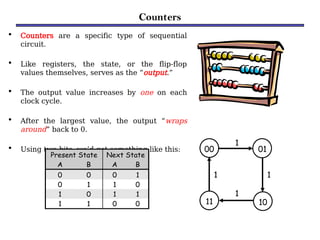
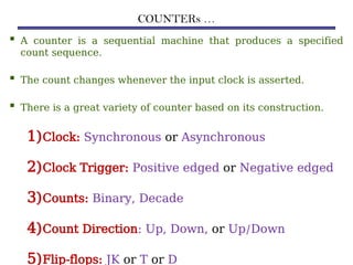
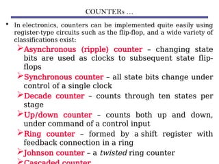
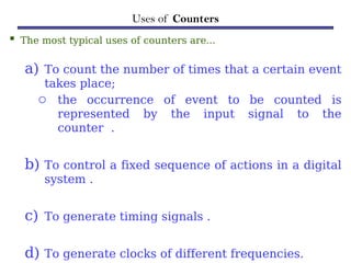
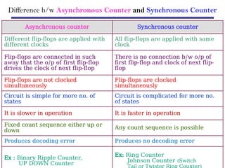
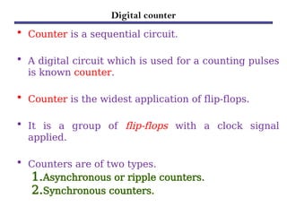
Counters
Counters
• Counters are a specific type of sequential
circuit.
• Like registers, the state, or the flip-flop
values themselves, serves as the “output.”
• The output value increases by one on each
clock cycle.
• After the largest value, the output “wraps
around” back to 0.
• Using two bits, we’d get something like this:
Present State Next State
A B A B
0 0 0 1
0 1 1 0
1 0 1 1
1 1 0 0
00 01
10
11
1
1
1
1
COUNTERs …
 A counter is a sequential machine that produces a specified
count sequence.
 The count changes whenever the input clock is asserted.
 There is a great variety of counter based on its construction.
1)Clock: Synchronous or Asynchronous
2)Clock Trigger: Positive edged or Negative edged
3)Counts: Binary, Decade
4)Count Direction: Up, Down, or Up/Down
5)Flip-flops: JK or T or D
COUNTERs …
• In electronics, counters can be implemented quite easily using
register-type circuits such as the flip-flop, and a wide variety of
classifications exist:
Asynchronous (ripple) counter – changing state
bits are used as clocks to subsequent state flip-
flops
Synchronous counter – all state bits change under
control of a single clock
Decade counter – counts through ten states per
stage
Up/down counter – counts both up and down,
under command of a control input
Ring counter – formed by a shift register with
feedback connection in a ring
Johnson counter – a twisted ring counter
Benefits of counters
• Counters can act as simple clocks to keep track of
“time.”
• You may need to record how many times something
has happened.
– How many bits have been sent or received?
– How many steps have been performed in some
computation?
• All processors contain a program counter, or PC.
– Programs consist of a list of instructions that are to
be executed one after another (for the most part).
– The PC keeps track of the instruction currently
being executed.
– The PC increments once on each clock cycle, and
Uses of Counters
 The most typical uses of counters are…
a) To count the number of times that a certain event
takes place;
o the occurrence of event to be counted is
represented by the input signal to the
counter .
b) To control a fixed sequence of actions in a digital
system .
c) To generate timing signals .
d) To generate clocks of different frequencies.
Difference b/w Asynchronous Counter and Synchronous Counter
Asynchronous counter Synchronous counter
Different flip-flops are applied with
different clocks
All flip-flops are applied with same
clock
Flip-flops are connected in such
away that the o/p of first flip-flop
drives the clock of next flip-flop
There is no connection b/w o/p of
first flip-flop and clock of next flip-
flop
Flip-flops are not clocked
simultaneously
Flip-flops are clocked
simultaneously
Circuit is simple for more no. of
states
Circuit is complicated for more no.
of states
It is slower in operation It is faster in operation
Fixed count sequence either up or
down
Any count sequence is possible
Produces decoding error Produces no decoding error
Ex : Binary Ripple Counter,
UP DOWN Counter
Ex: Ring Counter
Johnson Counter (Switch
Tail or Twister Ring Counter)
Digital counter
• Counter is a sequential circuit.
• A digital circuit which is used for a counting pulses
is known counter.
• Counter is the widest application of flip-flops.
• It is a group of flip-flops with a clock signal
applied.
• Counters are of two types.
1.Asynchronous or ripple counters.
2.Synchronous counters.
1. Asynchronous or ripple counters
• The logic diagram of a 2-bit ripple up counter is shown in
figure.
• The toggle (T) flip-flop are being used.
– But we can use the JK flip-flop also with J and K
connected permanently to logic 1.
• External clock is applied to the clock input of flip-flop A
and QA output is applied to the clock input of the next flip-
flop i.e. FF-B.
Logical Diagram:
1. Asynchronous or ripple counters …
Operation:
S.
N. Condition Operation
1
Initially let
both the FFs
be in the reset
state
• QBQA = 00 initially
2
After 1st
negative clock
edge
• As soon as the first negative clock edge is applied, FF-A will toggle and
QA will be equal to 1.
• QA is connected to clock input of FF-B.
• Since QA has changed from 0 to 1, it is treated as the positive clock edge by
FF-B.
• There is no change in QB because FF-B is a negative edge triggered FF.
• QBQA = 01 after the first clock pulse.
3
After 2nd
negative clock
edge
• On the arrival of second negative clock edge, FF-A toggles again and QA = 0.
• The change in QA acts as a negative clock edge for FF-B.
• So it will also toggle, and QB will be 1.
• QBQA = 10 after the second clock pulse.
4
After 3rd
negative clock
edge
• On the arrival of 3rd negative clock edge, FF-A toggles again and QA become
1 from 0.
• Since this is a positive going change, FF-B does not respond to it and
remains inactive.
• So QB does not change and continues to be equal to 1.
• QBQA = 11 after the third clock pulse.
5
After 4th
negative clock
• On the arrival of 4th negative clock edge, FF-A toggles again and QA becomes
1 from 0.
• This negative change in QA acts as clock pulse for FF-B.
1. Asynchronous or ripple counters …
Truth Table:
2. Synchronous counters
• If the "clock" pulses are applied to all the flip-flops in a counter
simultaneously, then such a counter is called as synchronous
counter.
2-bit Synchronous up counter:
• The JA and KA inputs of FF-A are tied to logic 1.
• So FF-A will work as a toggle flip-flop.
• The JB and KB inputs are connected to QA.
Logical Diagram:
2. Synchronous counters …
Operation:
S.
N.
Condition
Operation
1
Initially let
both the FFs
be in the
reset state
• QBQA = 00 initially.
2
After 1st
negative
clock edge
• As soon as the first negative clock edge is applied, FF-A will toggle and
QA will change from 0 to 1.
• But at the instant of application of negative clock edge, QA , JB = KB = 0.
• Hence FF-B will not change its state.
• So QB will remain 0.
• QBQA = 01 after the first clock pulse.
3
After 2nd
negative
clock edge
• On the arrival of second negative clock edge, FF-A toggles again and
QA changes from 1 to 0.
• But at this instant QA was 1.
• So JB = KB= 1 and FF-B will toggle.
• Hence QB changes from 0 to 1.
• QBQA = 10 after the second clock pulse.
4
After 3rd
negative
clock edge
• On application of the third falling clock edge, FF-A will toggle from 0 to 1
but there is no change of state for FF-B.
• QBQA = 11 after the third clock pulse.
5
After 4th
negative
clock edge
• On application of the next clock pulse, QA will change from 1 to 0 as QB will
also change from 1 to 0.
Q Q = 00 after the fourth clock pulse.
Classification of counters
• Depending on the way in which the counting progresses,
the synchronous or asynchronous counters are classified
as follows −
i. Up counters
ii.Down counters
iii.Up/Down counters
UP/DOWN Counter
• Up counter and down counter is combined together to obtain an
UP/DOWN counter.
• A mode control (M) input is also provided to select either up or
down mode.
• A combinational circuit is required to be designed and used
between each pair of flip-flop in order to achieve the up/down
operation.
Type of up/down counters:
 UP/DOWN ripple counters
 UP/DOWN synchronous counter
UP/DOWN Ripple Counters
• In the UP/DOWN ripple counter all the FFs operate in the
toggle mode.
– So either T flip-flops or JK flip-flops are to be used.
– The LSB flip-flop receives clock directly.
– But the clock to every other FF is obtained from (Q = Q bar)
output of the previous FF.
UP counting mode (M=0)
• The Q output of the preceding FF is connected to the clock of
the next stage if up counting is to be achieved.
• For this mode, the mode select input M is at logic 0 (M=0).
DOWN counting mode (M=1)
• If M = 1, then the Q bar output of the preceding FF is
connected to the next FF.
• This will operate the counter in the counting mode.
UP/DOWN Ripple Counters …
Example:
• 3-bit binary up/down ripple counter.
– 3-bit − hence three FFs are required.
– UP/DOWN − So a mode control input is essential.
– For a ripple up counter, the Q output of preceding FF is connected
to the clock input of the next one.
– For a ripple up counter, the Q output of preceding FF is connected
to the clock input of the next one.
– For a ripple down counter, the Q bar output of preceding FF is
connected to the clock input of the next one.
– Let the selection of Q and Q bar output of the preceding FF be
controlled by the mode control input M such that,
UP/DOWN Ripple Counters …
Block Diagram:
Truth Table:
2. Synchronous counters …
Operation:
S.
N. Condition
Operation
1
Case 1 :
With M = 0
(Up counting
mode)
• If M = 0 and M bar = 1, then the AND gates 1
and 3 in fig. will be enabled whereas the AND
gates 2 and 4 will be disabled.
• Hence QA gets connected to the clock input of
FF-B and QB gets connected to the clock input of
FF-C.
• These connections are same as those for the
normal up counter.
• Thus with M = 0 the circuit work as an up
counter.
2
Case 2:
With M = 1
(Down
counting
mode)
• If M = 1, then AND gates 2 and 4 in fig. are
enabled whereas the AND gates 1 and 3 are
disabled.
• Hence QA bar gets connected to the clock input
of FF-B and QB bar gets connected to the clock
input of FF-C.
• These connections will produce a down counter.
• Thus with M = 1 the circuit works as a down
Modulus Counter (MOD-N Counter)
• The 2-bit ripple counter is called as MOD-4
counter and 3-bit ripple counter is called as
MOD-8 counter.
• So in general, an n-bit ripple counter is called as
modulo-N counter.
– Where, MOD number = 2n.
Type of modulus:
–2-bit up or down (MOD-4)
–3-bit up or down (MOD-8)
–4-bit up or down (MOD-16)
Application of counters
Frequency counters
Digital clock
Time measurement
A to D converter
Frequency divider circuits
Digital triangular wavegenerator.
A slightly fancier counter
• Let’s try to design a slightly different two-bit counter:
– Again, the counter outputs will be 00, 01, 10 and 11.
– Now, there is a single input, X. When X=0, the counter value
should increment on each clock cycle.
– But when X=1, the value should decrement on successive
cycles.
• We’ll need two flip-flops again. Here are the four possible states:
00 01
10
11
The complete state diagram and table
00 01
10
11
0
0
0
1
0 1
1
1
Present State Inputs Next State
Q1 Q0 X Q1 Q0
0 0 0 0 1
0 0 1 1 1
0 1 0 1 0
0 1 1 0 0
1 0 0 1 1
1 0 1 0 1
1 1 0 0 0
1 1 1 1 0
• Here’s the complete state diagram and state table for this circuit.
D flip-flop inputs
• If we use D flip-flops, then the D inputs will just be the same as the
desired next states.
• Equations for the D flip-flop inputs are shown at the right.
• Why does D0 = Q0’ make sense?
Present State Inputs Next State
Q1 Q0 X Q1 Q0
0 0 0 0 1
0 0 1 1 1
0 1 0 1 0
0 1 1 0 0
1 0 0 1 1
1 0 1 0 1
1 1 0 0 0
1 1 1 1 0
Q0
0 1 0 1
Q1 1 0 1 0
X
Q0
1 1 0 0
Q1 1 1 0 0
X
D1 = Q1  Q0  X
D0 = Q0’
The counter in LogicWorks
• Here are some D Flip Flop
devices from LogicWorks.
• They have both normal and
complemented outputs, so we
can access Q0’ directly
without using an inverter.
(Q1’ is not needed in this
example.)
• This circuit counts normally
when Reset = 1. But when
Reset is 0, the flip-flop
outputs are cleared to 00
immediately.
• There is no three-input XOR
gate in Logic Works so we’ve
used a four-input version
instead, with one of the
JK flip-flop inputs
• If we use JK flip-flops instead, then we
have to compute the JK inputs for each
flip-flop.
• Look at the present and desired next state,
and use the excitation table on the right.
Present State Inputs Next State Flip flop inputs
Q1 Q0 X Q1 Q0 J1 K1 J0 K0
0 0 0 0 1 0 x 1 x
0 0 1 1 1 1 x 1 x
0 1 0 1 0 1 x x 1
0 1 1 0 0 0 x x 1
1 0 0 1 1 x 0 1 x
1 0 1 0 1 x 1 1 x
1 1 0 0 0 x 1 x 1
1 1 1 1 0 x 0 x 1
Q(t) Q(t+1) J K
0 0 0 x
0 1 1 x
1 0 x 1
1 1 x 0
JK flip-flop input equations
• We can then find equations for all four flip-flop inputs, in terms of
the present state and inputs. Here, it turns out J1 = K1 and J0 = K0.
J1 = K1 = Q0’ X + Q0 X’
J0 = K0 = 1
Present State Inputs Next State Flip flop inputs
Q1 Q0 X Q1 Q0 J1 K1 J0 K0
0 0 0 0 1 0 x 1 x
0 0 1 1 1 1 x 1 x
0 1 0 1 0 1 x x 1
0 1 1 0 0 0 x x 1
1 0 0 1 1 x 0 1 x
1 0 1 0 1 x 1 1 x
1 1 0 0 0 x 1 x 1
1 1 1 1 0 x 0 x 1
The counter in LogicWorks again
• Here is the counter again, but
using JK Flip Flop n.i. RS
devices instead.
• The direct inputs R and S are
non-inverted, or active-high.
• So this version of the circuit
counts normally when Reset
= 0, but initializes to 00 when
Reset is 1.
JK timing diagram
 The truth table for a negatively triggered JK flip-flop:
J K CK Q
0 0 ↓ Q0
0 1 ↓ 0
1 0 ↓ 1
1 1 ↓ Q'0
X X 0,1 Q0
JK timing diagram …
 The timing diagram for the negatively triggered JK flip-flop:
D timing diagram
 The truth table for a positive edge triggered D flip-flop:
D CK Q
0 ↑ 0
1 ↑ 1
X 0,1 Q0
D timing diagram …
 The timing diagram for the positive edge triggered D flip-flop:
Two Classes of Counters
 Counters are classified into two categories:
1)Asynchronous Counters (Ripple counters)
2)Synchronous Counters
Asynchronous & Synchronous
 Asynchronous: The events do not have a fixed time relationship with
each other and do not occur at the same time.
 Synchronous: The events have a fixed time relationship with each other
and do occur at the same time.
 Counters are classified according to the way they are clocked.
 In asynchronous counters, the first flip-flop is clocked by the
external clock pulse and then each successive flip-flop is by clocked
the output of the preceding flip-flop.
 In synchronous counters, the clock input is connected to all of the
flip-flop so that they are clocked simultaneously
Asynchronous Counters
 This counter is called
asynchronous because not all
flip flops are hooked to the
same clock.
 Look at the waveform of the
output, Q, in the timing
diagram.
 It resembles a clock as
well. If the period of the
clock is T, then what is
the period of Q, the
output of the flip flop?
It's 2T!
 We have a way to create a
clock that runs twice as slow.
 We feed the clock into a
T flip flop, where T is
hardwired to 1.
 The output will be a
Asynchronous counters
• If the clock has period T.
• Q0 has period 2T.
• Q1 period is 4T
• With n flip flops the
period is 2n
.
COMPARISON B/W SYNCHRONOUS & ASYNCHRONOUS COUNTERS
Asynchronous Synchronous
Circuit
The logic circuit of this type
of counters is simple to
design and we feed output of
one FF to clock of next FF
The circuit diagram for
type of counter becomes
difficult as number of
states increase in the
counter
Propaga
tion
Time
Propagation time delay of
this type of counter is :
Tpd = N * (Delay of 1 FF)
which is quiet high
N is number of FFs
Propagation time delay of
this type of counter is:
Tpd = (Delay of 1 FF) +
delay of 1 gate
Inclusion of delay of 1
gate would be illustrated
when we design higher
counters:
Maximu
m
operatin
g
And hence operating
frequency is Low
And hence operating
frequency is Higher
3 bit asynchronous “ripple” counter using T flip flops
• This is called as a
ripple counter due to
the way the FFs
respond one after
another in a kind of
rippling effect.
Synchronous Counters
• To eliminate the "ripple" effects, use a common clock
for each flip-flop and a combinational circuit to
generate the next state.
• For an up-counter,
use an incrementer =>
D3 Q3
D2 Q2
D1 Q1
D0 Q0
Clock
Incre-
mente
r
A3
A2
A1
A0
S3
S2
S1
S0
• Internal details =>
• Internal Logic
– XOR complements each bit
– AND chain causes complement
of a bit if all bits toward LSB
from it equal 1
• Count Enable
– Forces all outputs of AND
chain to 0 to “hold” the state
• Carry Out
– Added as part of incrementer
– Connect to Count Enable of
additional 4-bit counters to
form larger counters
Synchronous Counters (continued)
Incrementer
(a) Logic Diagram-Serial Gating
D
C
D
C
D
C
D
C
Count enable EN
Clock
Carry
output CO
Q0
Q1
Q2
Q3
Design Example: Synchronous BCD
• Use the sequential logic model to design a synchronous
BCD counter with D flip-flops
• State Table =>
• Input combinations
1010 through 1111
are don’t cares
Current State
Q8 Q4 Q2 Q1
Next State
Q8 Q4 Q2 Q1
0 0 0 0 0 0 0 1
0 0 0 1 0 0 1 0
0 0 1 0 0 0 1 1
0 0 1 1 0 1 0 0
0 1 0 0 0 1 0 1
0 1 0 1 0 1 1 0
0 1 1 0 0 1 1 1
0 1 1 1 1 0 0 0
1 0 0 0 1 0 0 1
1 0 0 1 0 0 0 0
Synchronous BCD (continued)
• Use K-Maps to two-level optimize the next state equations and
manipulate into forms containing XOR gates:
D1 = Q1’
• D2 = Q2 + Q1Q8’
D4 = Q4 + Q1Q2
D8 = Q8 + (Q1Q8 + Q1Q2Q4)
• Y = Q1Q8
• The logic diagram can be drawn from these equations
– An asynchronous or synchronous reset should be added
• What happens if the counter is perturbed by a power disturbance
or other interference and it enters a state other than 0000
through 1001?
• Find the actual values of the six next states for the don’t care
combinations from the equations
• Find the overall state diagram to assess behavior for the
don’t care states (states in decimal)
Synchronous BCD (continued)
Present State Next State
Q8 Q4 Q2 Q1 Q8 Q4 Q2 Q1
1 0 1 0 1 0 1 1
1 0 1 1 0 1 1 0
1 1 0 0 1 1 0 1
1 1 0 1 0 1 0 0
1 1 1 0 1 1 1 1
1 1 1 1 0 0 1 0
0
1
8
7
6
5
4
3
2
9
10
11
14
15
12
13
• For the BCD counter design, if an invalid state is entered,
return to a valid state occurs within two clock cycles
• Is this adequate?!
Synchronous BCD (continued)
Counting an arbitrary sequence
Unused states
• The examples shown so far have all had 2n
states, and used n flip-
flops. But sometimes you may have unused, leftover states.
• For example, here is a state table and diagram for a counter that
repeatedly counts from 0 (000) to 5 (101).
• What should we put in the table for the two unused states?
Present State Next State
Q2 Q1 Q0 Q2 Q1 Q0
0 0 0 0 0 1
0 0 1 0 1 0
0 1 0 0 1 1
0 1 1 1 0 0
1 0 0 1 0 1
1 0 1 0 0 0
1 1 0 ? ? ?
1 1 1 ? ? ?
001
010
011
100
101
000
Unused states can be don’t cares…
• To get the simplest possible circuit, you can fill in don’t cares for
the next states. This will also result in don’t cares for the flip-flop
inputs, which can simplify the hardware.
• If the circuit somehow ends up in one of the unused states (110
or 111), its behavior will depend on exactly what the don’t cares
were filled in with.
Present State Next State
Q2 Q1 Q0 Q2 Q1 Q0
0 0 0 0 0 1
0 0 1 0 1 0
0 1 0 0 1 1
0 1 1 1 0 0
1 0 0 1 0 1
1 0 1 0 0 0
1 1 0 x x x
1 1 1 x x x
001
010
011
100
101
000
…or maybe you do care
• To get the safest possible circuit, you can explicitly fill in next
states for the unused states 110 and 111.
• This guarantees that even if the circuit somehow enters an
unused state, it will eventually end up in a valid state.
• This is called a self-starting counter.
Present State Next State
Q2 Q1 Q0 Q2 Q1 Q0
0 0 0 0 0 1
0 0 1 0 1 0
0 1 0 0 1 1
0 1 1 1 0 0
1 0 0 1 0 1
1 0 1 0 0 0
1 1 0 0 0 0
1 1 1 0 0 0
001
010
011
100
101
000
111
110
LogicWorks counters
• There are a couple of different counters available in LogicWorks.
• The simplest one, the Counter-4 Min, just increments once on
each clock cycle.
– This is a four-bit counter, with values ranging from 0000 to
1111.
– The only “input” is the clock signal.
More complex counters
• More complex counters are also possible. The full-featured
LogicWorks Counter-4 device below has several functions.
– It can increment or decrement, by setting the UP input to 1 or
0.
– You can immediately (asynchronously) clear the counter to
0000 by setting CLR = 1.
– You can specify the counter’s next output by setting D3-D0 to
any four-bit value and clearing LD.
– The active-low EN input enables or disables the counter.
• When the counter is disabled, it continues to output the
same value without incrementing, decrementing, loading,
or clearing.
– The “counter out” CO is normally 1, but becomes 0
when the counter reaches its maximum value, 1111.
An 8-bit counter
• As you might expect by now, we can use
these general counters to build other
counters.
• Here is an 8-bit counter made from two 4-
bit counters.
– The bottom device represents the least
significant four bits, while the top
counter represents the most significant
four bits.
– When the bottom counter reaches 1111
(i.e., when CO = 0), it enables the top
counter for one cycle.
• Other implementation notes:
– The counters share clock and clear
signals.
A restricted 4-bit counter
• We can also make a counter that “starts” at some value besides
0000.
• In the diagram below, when CO=0 the LD signal forces the next
state to be loaded from D3-D0.
• The result is this counter wraps from 1111 to 0110 (instead of
0000).
Another restricted counter
• We can also make a circuit that counts up to only 1100, instead of
1111.
• Here, when the counter value reaches 1100, the NAND gate
forces the counter to load, so the next state becomes 0000.
Summary of Counters
• Counters serve many purposes in sequential logic design.
• There are lots of variations on the basic counter.
– Some can increment or decrement.
– An enable signal can be added.
– The counter’s value may be explicitly set.
• There are also several ways to make counters.
– You can follow the sequential design principles to build
counters from scratch.
– You could also modify or combine existing counter devices.

Counters-Counter is a sequential circuit.pptx

  • 1.
  • 2.
    Counters • Counters area specific type of sequential circuit. • Like registers, the state, or the flip-flop values themselves, serves as the “output.” • The output value increases by one on each clock cycle. • After the largest value, the output “wraps around” back to 0. • Using two bits, we’d get something like this: Present State Next State A B A B 0 0 0 1 0 1 1 0 1 0 1 1 1 1 0 0 00 01 10 11 1 1 1 1
  • 3.
    COUNTERs …  Acounter is a sequential machine that produces a specified count sequence.  The count changes whenever the input clock is asserted.  There is a great variety of counter based on its construction. 1)Clock: Synchronous or Asynchronous 2)Clock Trigger: Positive edged or Negative edged 3)Counts: Binary, Decade 4)Count Direction: Up, Down, or Up/Down 5)Flip-flops: JK or T or D
  • 4.
    COUNTERs … • Inelectronics, counters can be implemented quite easily using register-type circuits such as the flip-flop, and a wide variety of classifications exist: Asynchronous (ripple) counter – changing state bits are used as clocks to subsequent state flip- flops Synchronous counter – all state bits change under control of a single clock Decade counter – counts through ten states per stage Up/down counter – counts both up and down, under command of a control input Ring counter – formed by a shift register with feedback connection in a ring Johnson counter – a twisted ring counter
  • 5.
    Benefits of counters •Counters can act as simple clocks to keep track of “time.” • You may need to record how many times something has happened. – How many bits have been sent or received? – How many steps have been performed in some computation? • All processors contain a program counter, or PC. – Programs consist of a list of instructions that are to be executed one after another (for the most part). – The PC keeps track of the instruction currently being executed. – The PC increments once on each clock cycle, and
  • 6.
    Uses of Counters The most typical uses of counters are… a) To count the number of times that a certain event takes place; o the occurrence of event to be counted is represented by the input signal to the counter . b) To control a fixed sequence of actions in a digital system . c) To generate timing signals . d) To generate clocks of different frequencies.
  • 7.
    Difference b/w AsynchronousCounter and Synchronous Counter Asynchronous counter Synchronous counter Different flip-flops are applied with different clocks All flip-flops are applied with same clock Flip-flops are connected in such away that the o/p of first flip-flop drives the clock of next flip-flop There is no connection b/w o/p of first flip-flop and clock of next flip- flop Flip-flops are not clocked simultaneously Flip-flops are clocked simultaneously Circuit is simple for more no. of states Circuit is complicated for more no. of states It is slower in operation It is faster in operation Fixed count sequence either up or down Any count sequence is possible Produces decoding error Produces no decoding error Ex : Binary Ripple Counter, UP DOWN Counter Ex: Ring Counter Johnson Counter (Switch Tail or Twister Ring Counter)
  • 8.
    Digital counter • Counteris a sequential circuit. • A digital circuit which is used for a counting pulses is known counter. • Counter is the widest application of flip-flops. • It is a group of flip-flops with a clock signal applied. • Counters are of two types. 1.Asynchronous or ripple counters. 2.Synchronous counters.
  • 9.
    1. Asynchronous orripple counters • The logic diagram of a 2-bit ripple up counter is shown in figure. • The toggle (T) flip-flop are being used. – But we can use the JK flip-flop also with J and K connected permanently to logic 1. • External clock is applied to the clock input of flip-flop A and QA output is applied to the clock input of the next flip- flop i.e. FF-B. Logical Diagram:
  • 10.
    1. Asynchronous orripple counters … Operation: S. N. Condition Operation 1 Initially let both the FFs be in the reset state • QBQA = 00 initially 2 After 1st negative clock edge • As soon as the first negative clock edge is applied, FF-A will toggle and QA will be equal to 1. • QA is connected to clock input of FF-B. • Since QA has changed from 0 to 1, it is treated as the positive clock edge by FF-B. • There is no change in QB because FF-B is a negative edge triggered FF. • QBQA = 01 after the first clock pulse. 3 After 2nd negative clock edge • On the arrival of second negative clock edge, FF-A toggles again and QA = 0. • The change in QA acts as a negative clock edge for FF-B. • So it will also toggle, and QB will be 1. • QBQA = 10 after the second clock pulse. 4 After 3rd negative clock edge • On the arrival of 3rd negative clock edge, FF-A toggles again and QA become 1 from 0. • Since this is a positive going change, FF-B does not respond to it and remains inactive. • So QB does not change and continues to be equal to 1. • QBQA = 11 after the third clock pulse. 5 After 4th negative clock • On the arrival of 4th negative clock edge, FF-A toggles again and QA becomes 1 from 0. • This negative change in QA acts as clock pulse for FF-B.
  • 11.
    1. Asynchronous orripple counters … Truth Table:
  • 12.
    2. Synchronous counters •If the "clock" pulses are applied to all the flip-flops in a counter simultaneously, then such a counter is called as synchronous counter. 2-bit Synchronous up counter: • The JA and KA inputs of FF-A are tied to logic 1. • So FF-A will work as a toggle flip-flop. • The JB and KB inputs are connected to QA. Logical Diagram:
  • 13.
    2. Synchronous counters… Operation: S. N. Condition Operation 1 Initially let both the FFs be in the reset state • QBQA = 00 initially. 2 After 1st negative clock edge • As soon as the first negative clock edge is applied, FF-A will toggle and QA will change from 0 to 1. • But at the instant of application of negative clock edge, QA , JB = KB = 0. • Hence FF-B will not change its state. • So QB will remain 0. • QBQA = 01 after the first clock pulse. 3 After 2nd negative clock edge • On the arrival of second negative clock edge, FF-A toggles again and QA changes from 1 to 0. • But at this instant QA was 1. • So JB = KB= 1 and FF-B will toggle. • Hence QB changes from 0 to 1. • QBQA = 10 after the second clock pulse. 4 After 3rd negative clock edge • On application of the third falling clock edge, FF-A will toggle from 0 to 1 but there is no change of state for FF-B. • QBQA = 11 after the third clock pulse. 5 After 4th negative clock edge • On application of the next clock pulse, QA will change from 1 to 0 as QB will also change from 1 to 0. Q Q = 00 after the fourth clock pulse.
  • 14.
    Classification of counters •Depending on the way in which the counting progresses, the synchronous or asynchronous counters are classified as follows − i. Up counters ii.Down counters iii.Up/Down counters
  • 15.
    UP/DOWN Counter • Upcounter and down counter is combined together to obtain an UP/DOWN counter. • A mode control (M) input is also provided to select either up or down mode. • A combinational circuit is required to be designed and used between each pair of flip-flop in order to achieve the up/down operation. Type of up/down counters:  UP/DOWN ripple counters  UP/DOWN synchronous counter
  • 16.
    UP/DOWN Ripple Counters •In the UP/DOWN ripple counter all the FFs operate in the toggle mode. – So either T flip-flops or JK flip-flops are to be used. – The LSB flip-flop receives clock directly. – But the clock to every other FF is obtained from (Q = Q bar) output of the previous FF. UP counting mode (M=0) • The Q output of the preceding FF is connected to the clock of the next stage if up counting is to be achieved. • For this mode, the mode select input M is at logic 0 (M=0). DOWN counting mode (M=1) • If M = 1, then the Q bar output of the preceding FF is connected to the next FF. • This will operate the counter in the counting mode.
  • 17.
    UP/DOWN Ripple Counters… Example: • 3-bit binary up/down ripple counter. – 3-bit − hence three FFs are required. – UP/DOWN − So a mode control input is essential. – For a ripple up counter, the Q output of preceding FF is connected to the clock input of the next one. – For a ripple up counter, the Q output of preceding FF is connected to the clock input of the next one. – For a ripple down counter, the Q bar output of preceding FF is connected to the clock input of the next one. – Let the selection of Q and Q bar output of the preceding FF be controlled by the mode control input M such that,
  • 18.
    UP/DOWN Ripple Counters… Block Diagram: Truth Table:
  • 19.
    2. Synchronous counters… Operation: S. N. Condition Operation 1 Case 1 : With M = 0 (Up counting mode) • If M = 0 and M bar = 1, then the AND gates 1 and 3 in fig. will be enabled whereas the AND gates 2 and 4 will be disabled. • Hence QA gets connected to the clock input of FF-B and QB gets connected to the clock input of FF-C. • These connections are same as those for the normal up counter. • Thus with M = 0 the circuit work as an up counter. 2 Case 2: With M = 1 (Down counting mode) • If M = 1, then AND gates 2 and 4 in fig. are enabled whereas the AND gates 1 and 3 are disabled. • Hence QA bar gets connected to the clock input of FF-B and QB bar gets connected to the clock input of FF-C. • These connections will produce a down counter. • Thus with M = 1 the circuit works as a down
  • 20.
    Modulus Counter (MOD-NCounter) • The 2-bit ripple counter is called as MOD-4 counter and 3-bit ripple counter is called as MOD-8 counter. • So in general, an n-bit ripple counter is called as modulo-N counter. – Where, MOD number = 2n. Type of modulus: –2-bit up or down (MOD-4) –3-bit up or down (MOD-8) –4-bit up or down (MOD-16)
  • 21.
    Application of counters Frequencycounters Digital clock Time measurement A to D converter Frequency divider circuits Digital triangular wavegenerator.
  • 22.
    A slightly fanciercounter • Let’s try to design a slightly different two-bit counter: – Again, the counter outputs will be 00, 01, 10 and 11. – Now, there is a single input, X. When X=0, the counter value should increment on each clock cycle. – But when X=1, the value should decrement on successive cycles. • We’ll need two flip-flops again. Here are the four possible states: 00 01 10 11
  • 23.
    The complete statediagram and table 00 01 10 11 0 0 0 1 0 1 1 1 Present State Inputs Next State Q1 Q0 X Q1 Q0 0 0 0 0 1 0 0 1 1 1 0 1 0 1 0 0 1 1 0 0 1 0 0 1 1 1 0 1 0 1 1 1 0 0 0 1 1 1 1 0 • Here’s the complete state diagram and state table for this circuit.
  • 24.
    D flip-flop inputs •If we use D flip-flops, then the D inputs will just be the same as the desired next states. • Equations for the D flip-flop inputs are shown at the right. • Why does D0 = Q0’ make sense? Present State Inputs Next State Q1 Q0 X Q1 Q0 0 0 0 0 1 0 0 1 1 1 0 1 0 1 0 0 1 1 0 0 1 0 0 1 1 1 0 1 0 1 1 1 0 0 0 1 1 1 1 0 Q0 0 1 0 1 Q1 1 0 1 0 X Q0 1 1 0 0 Q1 1 1 0 0 X D1 = Q1  Q0  X D0 = Q0’
  • 25.
    The counter inLogicWorks • Here are some D Flip Flop devices from LogicWorks. • They have both normal and complemented outputs, so we can access Q0’ directly without using an inverter. (Q1’ is not needed in this example.) • This circuit counts normally when Reset = 1. But when Reset is 0, the flip-flop outputs are cleared to 00 immediately. • There is no three-input XOR gate in Logic Works so we’ve used a four-input version instead, with one of the
  • 26.
    JK flip-flop inputs •If we use JK flip-flops instead, then we have to compute the JK inputs for each flip-flop. • Look at the present and desired next state, and use the excitation table on the right. Present State Inputs Next State Flip flop inputs Q1 Q0 X Q1 Q0 J1 K1 J0 K0 0 0 0 0 1 0 x 1 x 0 0 1 1 1 1 x 1 x 0 1 0 1 0 1 x x 1 0 1 1 0 0 0 x x 1 1 0 0 1 1 x 0 1 x 1 0 1 0 1 x 1 1 x 1 1 0 0 0 x 1 x 1 1 1 1 1 0 x 0 x 1 Q(t) Q(t+1) J K 0 0 0 x 0 1 1 x 1 0 x 1 1 1 x 0
  • 27.
    JK flip-flop inputequations • We can then find equations for all four flip-flop inputs, in terms of the present state and inputs. Here, it turns out J1 = K1 and J0 = K0. J1 = K1 = Q0’ X + Q0 X’ J0 = K0 = 1 Present State Inputs Next State Flip flop inputs Q1 Q0 X Q1 Q0 J1 K1 J0 K0 0 0 0 0 1 0 x 1 x 0 0 1 1 1 1 x 1 x 0 1 0 1 0 1 x x 1 0 1 1 0 0 0 x x 1 1 0 0 1 1 x 0 1 x 1 0 1 0 1 x 1 1 x 1 1 0 0 0 x 1 x 1 1 1 1 1 0 x 0 x 1
  • 28.
    The counter inLogicWorks again • Here is the counter again, but using JK Flip Flop n.i. RS devices instead. • The direct inputs R and S are non-inverted, or active-high. • So this version of the circuit counts normally when Reset = 0, but initializes to 00 when Reset is 1.
  • 29.
    JK timing diagram The truth table for a negatively triggered JK flip-flop: J K CK Q 0 0 ↓ Q0 0 1 ↓ 0 1 0 ↓ 1 1 1 ↓ Q'0 X X 0,1 Q0
  • 30.
    JK timing diagram…  The timing diagram for the negatively triggered JK flip-flop:
  • 31.
    D timing diagram The truth table for a positive edge triggered D flip-flop: D CK Q 0 ↑ 0 1 ↑ 1 X 0,1 Q0
  • 32.
    D timing diagram…  The timing diagram for the positive edge triggered D flip-flop:
  • 33.
    Two Classes ofCounters  Counters are classified into two categories: 1)Asynchronous Counters (Ripple counters) 2)Synchronous Counters Asynchronous & Synchronous  Asynchronous: The events do not have a fixed time relationship with each other and do not occur at the same time.  Synchronous: The events have a fixed time relationship with each other and do occur at the same time.  Counters are classified according to the way they are clocked.  In asynchronous counters, the first flip-flop is clocked by the external clock pulse and then each successive flip-flop is by clocked the output of the preceding flip-flop.  In synchronous counters, the clock input is connected to all of the flip-flop so that they are clocked simultaneously
  • 34.
    Asynchronous Counters  Thiscounter is called asynchronous because not all flip flops are hooked to the same clock.  Look at the waveform of the output, Q, in the timing diagram.  It resembles a clock as well. If the period of the clock is T, then what is the period of Q, the output of the flip flop? It's 2T!  We have a way to create a clock that runs twice as slow.  We feed the clock into a T flip flop, where T is hardwired to 1.  The output will be a
  • 35.
    Asynchronous counters • Ifthe clock has period T. • Q0 has period 2T. • Q1 period is 4T • With n flip flops the period is 2n .
  • 36.
    COMPARISON B/W SYNCHRONOUS& ASYNCHRONOUS COUNTERS Asynchronous Synchronous Circuit The logic circuit of this type of counters is simple to design and we feed output of one FF to clock of next FF The circuit diagram for type of counter becomes difficult as number of states increase in the counter Propaga tion Time Propagation time delay of this type of counter is : Tpd = N * (Delay of 1 FF) which is quiet high N is number of FFs Propagation time delay of this type of counter is: Tpd = (Delay of 1 FF) + delay of 1 gate Inclusion of delay of 1 gate would be illustrated when we design higher counters: Maximu m operatin g And hence operating frequency is Low And hence operating frequency is Higher
  • 37.
    3 bit asynchronous“ripple” counter using T flip flops • This is called as a ripple counter due to the way the FFs respond one after another in a kind of rippling effect.
  • 38.
    Synchronous Counters • Toeliminate the "ripple" effects, use a common clock for each flip-flop and a combinational circuit to generate the next state. • For an up-counter, use an incrementer => D3 Q3 D2 Q2 D1 Q1 D0 Q0 Clock Incre- mente r A3 A2 A1 A0 S3 S2 S1 S0
  • 39.
    • Internal details=> • Internal Logic – XOR complements each bit – AND chain causes complement of a bit if all bits toward LSB from it equal 1 • Count Enable – Forces all outputs of AND chain to 0 to “hold” the state • Carry Out – Added as part of incrementer – Connect to Count Enable of additional 4-bit counters to form larger counters Synchronous Counters (continued) Incrementer (a) Logic Diagram-Serial Gating D C D C D C D C Count enable EN Clock Carry output CO Q0 Q1 Q2 Q3
  • 40.
    Design Example: SynchronousBCD • Use the sequential logic model to design a synchronous BCD counter with D flip-flops • State Table => • Input combinations 1010 through 1111 are don’t cares Current State Q8 Q4 Q2 Q1 Next State Q8 Q4 Q2 Q1 0 0 0 0 0 0 0 1 0 0 0 1 0 0 1 0 0 0 1 0 0 0 1 1 0 0 1 1 0 1 0 0 0 1 0 0 0 1 0 1 0 1 0 1 0 1 1 0 0 1 1 0 0 1 1 1 0 1 1 1 1 0 0 0 1 0 0 0 1 0 0 1 1 0 0 1 0 0 0 0
  • 41.
    Synchronous BCD (continued) •Use K-Maps to two-level optimize the next state equations and manipulate into forms containing XOR gates: D1 = Q1’ • D2 = Q2 + Q1Q8’ D4 = Q4 + Q1Q2 D8 = Q8 + (Q1Q8 + Q1Q2Q4) • Y = Q1Q8 • The logic diagram can be drawn from these equations – An asynchronous or synchronous reset should be added • What happens if the counter is perturbed by a power disturbance or other interference and it enters a state other than 0000 through 1001?
  • 42.
    • Find theactual values of the six next states for the don’t care combinations from the equations • Find the overall state diagram to assess behavior for the don’t care states (states in decimal) Synchronous BCD (continued) Present State Next State Q8 Q4 Q2 Q1 Q8 Q4 Q2 Q1 1 0 1 0 1 0 1 1 1 0 1 1 0 1 1 0 1 1 0 0 1 1 0 1 1 1 0 1 0 1 0 0 1 1 1 0 1 1 1 1 1 1 1 1 0 0 1 0 0 1 8 7 6 5 4 3 2 9 10 11 14 15 12 13
  • 43.
    • For theBCD counter design, if an invalid state is entered, return to a valid state occurs within two clock cycles • Is this adequate?! Synchronous BCD (continued)
  • 44.
  • 45.
    Unused states • Theexamples shown so far have all had 2n states, and used n flip- flops. But sometimes you may have unused, leftover states. • For example, here is a state table and diagram for a counter that repeatedly counts from 0 (000) to 5 (101). • What should we put in the table for the two unused states? Present State Next State Q2 Q1 Q0 Q2 Q1 Q0 0 0 0 0 0 1 0 0 1 0 1 0 0 1 0 0 1 1 0 1 1 1 0 0 1 0 0 1 0 1 1 0 1 0 0 0 1 1 0 ? ? ? 1 1 1 ? ? ? 001 010 011 100 101 000
  • 46.
    Unused states canbe don’t cares… • To get the simplest possible circuit, you can fill in don’t cares for the next states. This will also result in don’t cares for the flip-flop inputs, which can simplify the hardware. • If the circuit somehow ends up in one of the unused states (110 or 111), its behavior will depend on exactly what the don’t cares were filled in with. Present State Next State Q2 Q1 Q0 Q2 Q1 Q0 0 0 0 0 0 1 0 0 1 0 1 0 0 1 0 0 1 1 0 1 1 1 0 0 1 0 0 1 0 1 1 0 1 0 0 0 1 1 0 x x x 1 1 1 x x x 001 010 011 100 101 000
  • 47.
    …or maybe youdo care • To get the safest possible circuit, you can explicitly fill in next states for the unused states 110 and 111. • This guarantees that even if the circuit somehow enters an unused state, it will eventually end up in a valid state. • This is called a self-starting counter. Present State Next State Q2 Q1 Q0 Q2 Q1 Q0 0 0 0 0 0 1 0 0 1 0 1 0 0 1 0 0 1 1 0 1 1 1 0 0 1 0 0 1 0 1 1 0 1 0 0 0 1 1 0 0 0 0 1 1 1 0 0 0 001 010 011 100 101 000 111 110
  • 48.
    LogicWorks counters • Thereare a couple of different counters available in LogicWorks. • The simplest one, the Counter-4 Min, just increments once on each clock cycle. – This is a four-bit counter, with values ranging from 0000 to 1111. – The only “input” is the clock signal.
  • 49.
    More complex counters •More complex counters are also possible. The full-featured LogicWorks Counter-4 device below has several functions. – It can increment or decrement, by setting the UP input to 1 or 0. – You can immediately (asynchronously) clear the counter to 0000 by setting CLR = 1. – You can specify the counter’s next output by setting D3-D0 to any four-bit value and clearing LD. – The active-low EN input enables or disables the counter. • When the counter is disabled, it continues to output the same value without incrementing, decrementing, loading, or clearing. – The “counter out” CO is normally 1, but becomes 0 when the counter reaches its maximum value, 1111.
  • 50.
    An 8-bit counter •As you might expect by now, we can use these general counters to build other counters. • Here is an 8-bit counter made from two 4- bit counters. – The bottom device represents the least significant four bits, while the top counter represents the most significant four bits. – When the bottom counter reaches 1111 (i.e., when CO = 0), it enables the top counter for one cycle. • Other implementation notes: – The counters share clock and clear signals.
  • 51.
    A restricted 4-bitcounter • We can also make a counter that “starts” at some value besides 0000. • In the diagram below, when CO=0 the LD signal forces the next state to be loaded from D3-D0. • The result is this counter wraps from 1111 to 0110 (instead of 0000).
  • 52.
    Another restricted counter •We can also make a circuit that counts up to only 1100, instead of 1111. • Here, when the counter value reaches 1100, the NAND gate forces the counter to load, so the next state becomes 0000.
  • 53.
    Summary of Counters •Counters serve many purposes in sequential logic design. • There are lots of variations on the basic counter. – Some can increment or decrement. – An enable signal can be added. – The counter’s value may be explicitly set. • There are also several ways to make counters. – You can follow the sequential design principles to build counters from scratch. – You could also modify or combine existing counter devices.

Editor's Notes

  • #43 Error = Q8 Q4 + Q8 Q2