Download to read offline
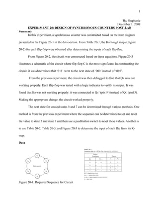

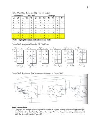
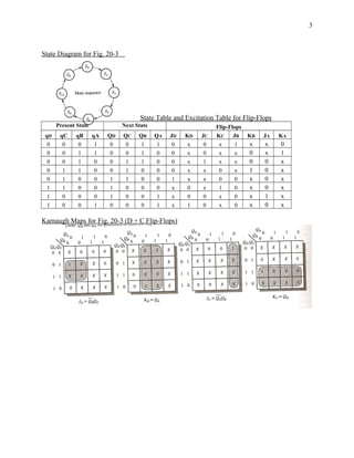
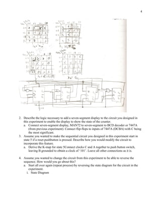
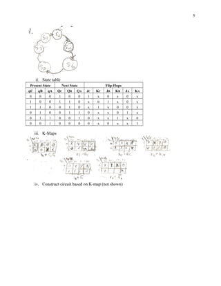


The document describes an experiment where a student constructed a synchronous counter circuit based on a given state diagram and state table. The circuit was built using Karnaugh maps to determine the inputs for each flip-flop. The circuit was tested and debugged after it was found one flip-flop was not working properly due to an incorrect connection. Methods for determining the next states for unused states in the state table are also discussed.


![[Speech3] Draft002](https://cdn.slidesharecdn.com/ss_thumbnails/63571e48-dcb3-4e06-bde3-3a90af7bd448-160809163414-thumbnail.jpg?width=640&height=640&fit=bounds)
![[EXPERIMENT6+7] Heat_treatment_and_Hardenability](https://cdn.slidesharecdn.com/ss_thumbnails/3c0f8433-ffb0-47c0-be22-f17bdc608da1-160711030447-thumbnail.jpg?width=640&height=640&fit=bounds)


![[EXPERIMENT2] CHARPY IMPACT TESTING MEMO REPORT](https://cdn.slidesharecdn.com/ss_thumbnails/cbd390e5-b46c-453f-b899-38589f76287d-160711030333-thumbnail.jpg?width=640&height=640&fit=bounds)