Downloaded 50 times


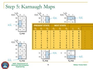


The document describes the steps to design a synchronous counter using sequential logic circuits. It begins with defining the learning outcomes as being able to design a counter through 7 steps: 1) state diagram, 2) next-state table, 3) flip-flop transition table, 4) circuit excitation table, 5) Karnaugh maps, 6) logic expressions, and 7) implementation. It then provides examples working through each step to design a 3-bit Gray code counter using J-K flip-flops. Exercises are provided to design additional counters.