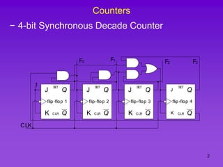
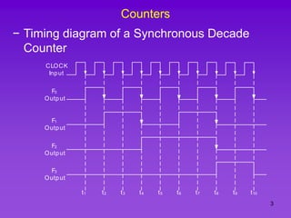
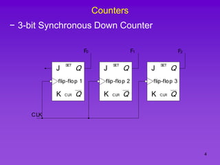
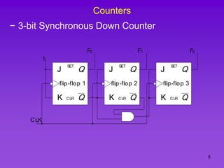
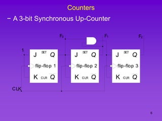
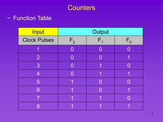
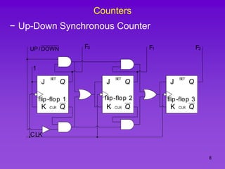
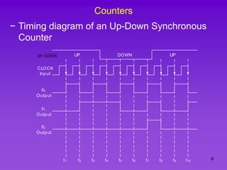
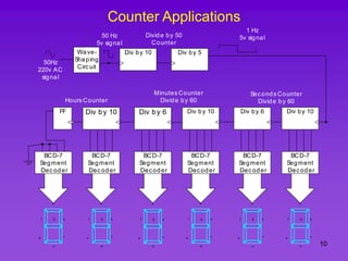
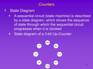
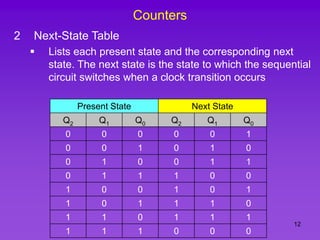
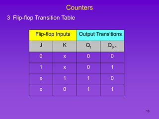
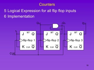
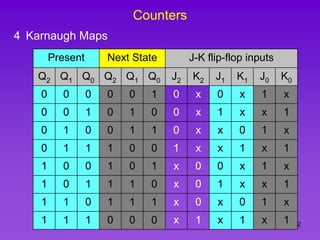
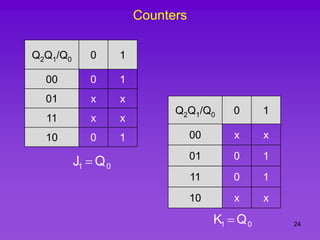
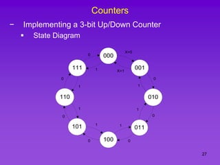
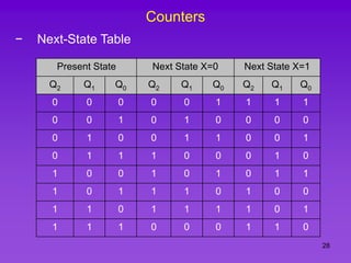
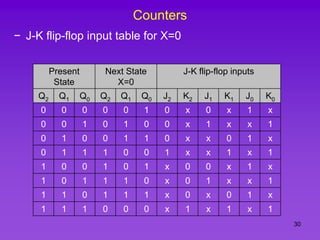
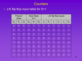
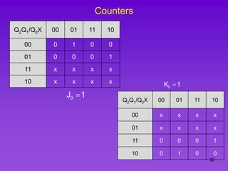
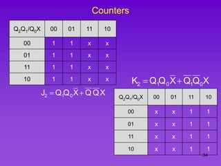
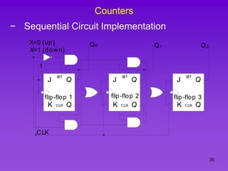
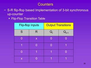
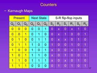
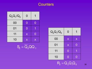
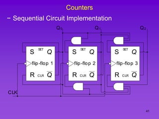
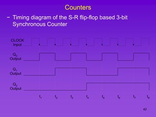
1
Computer Logic & Design
Fall 2005
t0 t4 t5 t6
t1 t2 t3
A
B
F
Sana Ullah Qaisar
Lecturer, Telecom. Engineering
NUCES, Islamabad
2
Counters
− 4-bit Synchronous Decade Counter
J
Q
Q
K
SET
CLR
flip-flop 1
CLK
J
Q
Q
K
SET
CLR
flip-flop 2
J
Q
Q
K
SET
CLR
flip-flop 3
J
Q
Q
K
SET
CLR
flip-flop 4
1
F0 F1 F2 F3
3
Counters
− Timing diagram of a Synchronous Decade
Counter
CLOCK
Input
F0
Output
F1
Output
t1 t2 t3 t4 t5 t6 t7 t8
F2
Output
F3
Output
t9 t10
4
Counters
− 3-bit Synchronous Down Counter
J
Q
Q
K
SET
CLR
flip-flop 1
CLK
J
Q
Q
K
SET
CLR
flip-flop 2
J
Q
Q
K
SET
CLR
flip-flop 3
F0 F1 F2
5
Counters
− 3-bit Synchronous Down Counter
J
Q
Q
K
SET
CLR
flip-flop 1
1
CLK
J
Q
Q
K
SET
CLR
flip-flop 2
J
Q
Q
K
SET
CLR
flip-flop 3
F0 F1 F2
6
Counters
− A 3-bit Synchronous Up-Counter
J
Q
Q
K
SET
CLR
flip-flop 1
1
CLK
J
Q
Q
K
SET
CLR
flip-flop 2
J
Q
Q
K
SET
CLR
flip-flop 3
F0 F1 F2
7
Counters
− Function Table
Input Output
Clock Pulses F2 F1 F0
1 0 0 0
2 0 0 1
3 0 1 0
4 0 1 1
5 1 0 0
6 1 0 1
7 1 1 0
8 1 1 1
8
Counters
− Up-Down Synchronous Counter
J
Q
Q
K
SET
CLR
flip-flop 1
1
CLK
J
Q
Q
K
SET
CLR
flip-flop 2
J
Q
Q
K
SET
CLR
flip-flop 3
F0 F1 F2
DOWN
/
UP
9
Counters
− Timing diagram of an Up-Down Synchronous
Counter
CLOCK
Input
F0
Output
F1
Output
t1 t2 t3 t4 t5 t6 t7 t8
F2
Output
t9 t10
UP DOWN UP
DOWN
/
UP
10
Counter Applications
Div by 10
Div by 6
Div by 10
Div by 6
Div by 10
FF
Div by 5
Div by 10
BCD-7
Segment
Decoder
a
b
c
d
e
f g
BCD-7
Segment
Decoder
a
b
c
d
e
f g
BCD-7
Segment
Decoder
a
b
c
d
e
f g
BCD-7
Segment
Decoder
a
b
c
d
e
f g
BCD-7
Segment
Decoder
a
b
c
d
e
f g
BCD-7
Segment
Decoder
a
b
c
d
e
f g
Wave-
Shaping
Circuit
50Hz
220v AC
signal
50 Hz
5v signal
1 Hz
5v signal
Seconds Counter
Divide by 60
Minutes Counter
Divide by 60
Hours Counter
Divide by 50
Counter
11
Counters
1 State Diagram
 A sequential circuit (state machine) is described
by a state diagram, which shows the sequence
of state through which the sequential circuit
progresses when it is clocked
 State diagram of a 3-bit Up-Counter
111
110
011
001
000
101
010
100
12
Counters
2 Next-State Table
 Lists each present state and the corresponding next
state. The next state is the state to which the sequential
circuit switches when a clock transition occurs
Present State Next State
Q2 Q1 Q0 Q2 Q1 Q0
0 0 0 0 0 1
0 0 1 0 1 0
0 1 0 0 1 1
0 1 1 1 0 0
1 0 0 1 0 1
1 0 1 1 1 0
1 1 0 1 1 1
1 1 1 0 0 0
13
Counters
3 Flip-flop Transition Table
Flip-flop Inputs Output Transitions
J K Qt Qt+1
0 x 0 0
1 x 0 1
x 1 1 0
x 0 1 1
14
Counters
4 Karnaugh Maps
Present Next State J-K flip-flop inputs
Q2 Q1 Q0 Q2 Q1 Q0 J2 K2 J1 K1 J0 K0
0 0 0 0 0 1 0 x 0 x 1 x
0 0 1 0 1 0 0 x 1 x x 1
0 1 0 0 1 1 0 x x 0 1 x
0 1 1 1 0 0 1 x x 1 x 1
1 0 0 1 0 1 x 0 0 x 1 x
1 0 1 1 1 0 x 0 1 x x 1
1 1 0 1 1 1 x 0 x 0 1 x
1 1 1 0 0 0 x 1 x 1 x 1
15
Counters
Q2Q1/Q0 0 1
00 0 0
01 0 1
11 x x
10 x x
0
1
2 Q
Q
J 
Q2Q1/Q0 0 1
00 X X
01 X X
11 0 1
10 0 0
0
1
2 Q
Q
K 
16
Counters
Q2Q1/Q0 0 1
00 0 1
01 x x
11 x x
10 0 1
0
1 Q
J 
Q2Q1/Q0 0 1
00 x x
01 0 1
11 0 1
10 x x
0
1 Q
K 
17
Counters
Q2Q1/Q0 0 1
00 1 x
01 1 x
11 1 x
10 1 x
1
J0 
Q2Q1/Q0 0 1
00 x 1
01 x 1
11 x 1
10 x 1
1
K0 
18
Counters
5 Logical Expression for all flip flop inputs
6 Implementation
J
Q
Q
K
SET
CLR
flip-flop 1
1
CLK
J
Q
Q
K
SET
CLR
flip-flop 2
J
Q
Q
K
SET
CLR
flip-flop 3
Q0 Q1 Q2
19
Counters
1 State Diagram
 A sequential circuit (state machine) is described
by a state diagram, which shows the sequence
of state through which the sequential circuit
progresses when it is clocked
 State diagram of a 3-bit Up-Counter
111
110
011
001
000
101
010
100
20
Counters
2 Next-State Table
 Lists each present state and the corresponding next
state. The next state is the state to which the sequential
circuit switches when a clock transition occurs
Present State Next State
Q2 Q1 Q0 Q2 Q1 Q0
0 0 0 0 0 1
0 0 1 0 1 0
0 1 0 0 1 1
0 1 1 1 0 0
1 0 0 1 0 1
1 0 1 1 1 0
1 1 0 1 1 1
1 1 1 0 0 0
21
Counters
3 Flip-flop Transition Table
Flip-flop Inputs Output Transitions
J K Qt Qt+1
0 x 0 0
1 x 0 1
x 1 1 0
x 0 1 1
22
Counters
4 Karnaugh Maps
Present Next State J-K flip-flop inputs
Q2 Q1 Q0 Q2 Q1 Q0 J2 K2 J1 K1 J0 K0
0 0 0 0 0 1 0 x 0 x 1 x
0 0 1 0 1 0 0 x 1 x x 1
0 1 0 0 1 1 0 x x 0 1 x
0 1 1 1 0 0 1 x x 1 x 1
1 0 0 1 0 1 x 0 0 x 1 x
1 0 1 1 1 0 x 0 1 x x 1
1 1 0 1 1 1 x 0 x 0 1 x
1 1 1 0 0 0 x 1 x 1 x 1
23
Counters
Q2Q1/Q0 0 1
00 0 0
01 0 1
11 x x
10 x x
0
1
2 Q
Q
J 
Q2Q1/Q0 0 1
00 X X
01 X X
11 0 1
10 0 0
0
1
2 Q
Q
K 
24
Counters
Q2Q1/Q0 0 1
00 0 1
01 x x
11 x x
10 0 1
0
1 Q
J 
Q2Q1/Q0 0 1
00 x x
01 0 1
11 0 1
10 x x
0
1 Q
K 
25
Counters
Q2Q1/Q0 0 1
00 1 x
01 1 x
11 1 x
10 1 x
1
J0 
Q2Q1/Q0 0 1
00 x 1
01 x 1
11 x 1
10 x 1
1
K0 
26
Counters
5 Logical Expression for all flip flop inputs
6 Implementation
J
Q
Q
K
SET
CLR
flip-flop 1
1
CLK
J
Q
Q
K
SET
CLR
flip-flop 2
J
Q
Q
K
SET
CLR
flip-flop 3
Q0 Q1 Q2
27
Counters
− Implementing a 3-bit Up/Down Counter
 State Diagram
111
110
011
001
000
101
010
100
X=0
X=1
0
0
0
0
0
0
0
1
1
1
1
1
1
1
28
Counters
− Next-State Table
Present State Next State X=0 Next State X=1
Q2 Q1 Q0 Q2 Q1 Q0 Q2 Q1 Q0
0 0 0 0 0 1 1 1 1
0 0 1 0 1 0 0 0 0
0 1 0 0 1 1 0 0 1
0 1 1 1 0 0 0 1 0
1 0 0 1 0 1 0 1 1
1 0 1 1 1 0 1 0 0
1 1 0 1 1 1 1 0 1
1 1 1 0 0 0 1 1 0
29
Counters
3 Flip-flop Transition Table
Flip-flop Inputs Output Transitions
J K Qt Qt+1
0 x 0 0
1 x 0 1
x 1 1 0
x 0 1 1
30
Counters
− J-K flip-flop input table for X=0
Present
State
Next State
X=0
J-K flip-flop inputs
Q2 Q1 Q0 Q2 Q1 Q0 J2 K2 J1 K1 J0 K0
0 0 0 0 0 1 0 x 0 x 1 x
0 0 1 0 1 0 0 x 1 x x 1
0 1 0 0 1 1 0 x x 0 1 x
0 1 1 1 0 0 1 x x 1 x 1
1 0 0 1 0 1 x 0 0 x 1 x
1 0 1 1 1 0 x 0 1 x x 1
1 1 0 1 1 1 x 0 x 0 1 x
1 1 1 0 0 0 x 1 x 1 x 1
31
Counters
− J-K flip-flop input table for X=1
Present
State
Next State
X=1
J-K flip-flop inputs
Q2 Q1 Q0 Q2 Q1 Q0 J2 K2 J1 K1 J0 K0
0 0 0 1 1 1 1 x 1 x 1 x
0 0 1 0 0 0 0 x 0 x x 1
0 1 0 0 0 1 0 x x 1 1 x
0 1 1 0 1 0 0 x x 0 x 1
1 0 0 0 1 1 x 1 1 x 1 x
1 0 1 1 0 0 x 0 0 x x 1
1 1 0 1 0 1 x 0 x 1 1 x
1 1 1 1 1 0 x 0 x 0 x 1
32
Counters
Q2Q1/Q0X 00 01 11 10
00 0 1 0 0
01 0 0 0 1
11 x x x x
10 x x x x
1
J0 
Q2Q1/Q0X 00 01 11 10
00 x x x x
01 x x x x
11 0 0 0 1
10 0 1 0 0
1
K0 
33
Counters
Q2Q1/Q0X 00 01 11 10
00 0 1 0 1
01 x x x x
11 x x x x
10 0 1 0 1
X
Q
J 0
1  Q2Q1/Q0X 00 01 11 10
00 x x x x
01 0 1 0 1
11 0 1 0 1
10 x x x x
X
Q
K 0
1 
34
Counters
Q2Q1/Q0X 00 01 11 10
00 1 1 x x
01 1 1 x x
11 1 1 x x
10 1 1 x x
X
Q
Q
X
Q
Q
J 0
1
2 
 Q2Q1/Q0X 00 01 11 10
00 x x 1 1
01 x x 1 1
11 x x 1 1
10 x x 1 1
X
Q
Q
X
Q
Q
K 0
1
0
1
2 

35
Counters
− Sequential Circuit Implementation
J
Q
Q
K
SET
CLR
flip-flop 1
1
CLK
J
Q
Q
K
SET
CLR
flip-flop 2
J
Q
Q
K
SET
CLR
flip-flop 3
Q0 Q1 Q2
X=0 (up)
X=1 (down)
36
Counters
− S-R flip-flop based Implementation of 3-bit synchronous
up-counter
 Flip-Flop Transition Table
Flip-flop Inputs Output Transitions
S R Qt Qt+1
0 x 0 0
1 0 0 1
0 1 1 0
x 0 1 1
37
Counters
− Karnaugh Maps
Present Next State S-R flip-flop inputs
Q2 Q1 Q0 Q2 Q1 Q0 S2 R2 S1 R1 S0 R0
0 0 0 0 0 1 0 x 0 x 1 0
0 0 1 0 1 0 0 x 1 0 0 1
0 1 0 0 1 1 0 x x 0 1 0
0 1 1 1 0 0 1 0 0 1 0 1
1 0 0 1 0 1 x 0 0 x 1 0
1 0 1 1 1 0 x 0 1 0 0 1
1 1 0 1 1 1 x 0 x 0 1 0
1 1 1 0 0 0 0 1 0 1 0 1
38
Counters
Q2Q1/Q0 0 1
00 0 0
01 0 1
11 x 0
10 x x
1
2
2 QQ
Q
S 
Q2Q1/Q0 0 1
00 x x
01 x 0
11 0 1
10 0 0
0
1
2
2 Q
Q
Q
R 
39
Counters
Q2Q1/Q0 0 1
00 0 0
01 x 0
11 x 0
10 0 1
0
1
1 Q
Q
S 
Q2Q1/Q0 0 1
00 x 0
01 0 1
11 0 1
10 x 0
0
1
1 Q
Q
R 
40
Counters
Q2Q1/Q0 0 1
00 1 0
01 1 0
11 1 0
10 1 0
0
0 Q
S 
Q2Q1/Q0 0 1
00 0 1
01 0 1
11 0 1
10 0 1
0
0 Q
R 
41
Counters
− Sequential Circuit Implementation
Q
Q
SET
CLR
S
R
flip-flop 1
CLK
Q
Q
SET
CLR
S
R
flip-flop 2
Q
Q
SET
CLR
S
R
flip-flop 3
Q0 Q1 Q2
42
Counters
− Timing diagram of the S-R flip-flop based 3-bit
Synchronous Counter
CLOCK
Input
Q0
Output
Q1
Output
t1 t2 t3 t4 t5 t6 t7 t8
Q2
Output
43
Counters
− Flip-Flop Transition Table
Flip-flop Inputs Output Transitions
D Qt+1
1 1
0 0
44
Counters
− D flip-flop input table
Present State Next State D flip-flop inputs
Q2 Q1 Q0 Q2 Q1 Q0 D2 D1 D0
0 0 0 0 0 1 0 0 1
0 0 1 0 1 0 0 1 0
0 1 0 0 1 1 0 1 1
0 1 1 1 0 0 1 0 0
1 0 0 1 0 1 1 0 1
1 0 1 1 1 0 1 1 0
1 1 0 1 1 1 1 1 1
1 1 1 0 0 0 0 0 0
45
Counters
Q2Q1/Q0 0 1
00 0 0
01 0 1
11 1 0
10 1 1
Q2Q1/Q0 0 1
00 1 0
01 1 0
11 1 0
10 1 0
Q2Q1/Q0 0 1
00 0 0
01 0 1
11 1 0
10 1 1
0
0 Q
D 
46
Counters
− D flip-flop based implementation of 3-bit
Synchronous Counter
Q
Q
SET
CLR
D
flip-flop 1
CLK
Q
Q
SET
CLR
D
flip-flop 2
Q
Q
SET
CLR
D
flip-flop 3
Q0 Q1 Q2

Synchronous decade counters in digital logic design

  • 1.
    1 Computer Logic &Design Fall 2005 t0 t4 t5 t6 t1 t2 t3 A B F Sana Ullah Qaisar Lecturer, Telecom. Engineering NUCES, Islamabad
  • 2.
    2 Counters − 4-bit SynchronousDecade Counter J Q Q K SET CLR flip-flop 1 CLK J Q Q K SET CLR flip-flop 2 J Q Q K SET CLR flip-flop 3 J Q Q K SET CLR flip-flop 4 1 F0 F1 F2 F3
  • 3.
    3 Counters − Timing diagramof a Synchronous Decade Counter CLOCK Input F0 Output F1 Output t1 t2 t3 t4 t5 t6 t7 t8 F2 Output F3 Output t9 t10
  • 4.
    4 Counters − 3-bit SynchronousDown Counter J Q Q K SET CLR flip-flop 1 CLK J Q Q K SET CLR flip-flop 2 J Q Q K SET CLR flip-flop 3 F0 F1 F2
  • 5.
    5 Counters − 3-bit SynchronousDown Counter J Q Q K SET CLR flip-flop 1 1 CLK J Q Q K SET CLR flip-flop 2 J Q Q K SET CLR flip-flop 3 F0 F1 F2
  • 6.
    6 Counters − A 3-bitSynchronous Up-Counter J Q Q K SET CLR flip-flop 1 1 CLK J Q Q K SET CLR flip-flop 2 J Q Q K SET CLR flip-flop 3 F0 F1 F2
  • 7.
    7 Counters − Function Table InputOutput Clock Pulses F2 F1 F0 1 0 0 0 2 0 0 1 3 0 1 0 4 0 1 1 5 1 0 0 6 1 0 1 7 1 1 0 8 1 1 1
  • 8.
    8 Counters − Up-Down SynchronousCounter J Q Q K SET CLR flip-flop 1 1 CLK J Q Q K SET CLR flip-flop 2 J Q Q K SET CLR flip-flop 3 F0 F1 F2 DOWN / UP
  • 9.
    9 Counters − Timing diagramof an Up-Down Synchronous Counter CLOCK Input F0 Output F1 Output t1 t2 t3 t4 t5 t6 t7 t8 F2 Output t9 t10 UP DOWN UP DOWN / UP
  • 10.
    10 Counter Applications Div by10 Div by 6 Div by 10 Div by 6 Div by 10 FF Div by 5 Div by 10 BCD-7 Segment Decoder a b c d e f g BCD-7 Segment Decoder a b c d e f g BCD-7 Segment Decoder a b c d e f g BCD-7 Segment Decoder a b c d e f g BCD-7 Segment Decoder a b c d e f g BCD-7 Segment Decoder a b c d e f g Wave- Shaping Circuit 50Hz 220v AC signal 50 Hz 5v signal 1 Hz 5v signal Seconds Counter Divide by 60 Minutes Counter Divide by 60 Hours Counter Divide by 50 Counter
  • 11.
    11 Counters 1 State Diagram A sequential circuit (state machine) is described by a state diagram, which shows the sequence of state through which the sequential circuit progresses when it is clocked  State diagram of a 3-bit Up-Counter 111 110 011 001 000 101 010 100
  • 12.
    12 Counters 2 Next-State Table Lists each present state and the corresponding next state. The next state is the state to which the sequential circuit switches when a clock transition occurs Present State Next State Q2 Q1 Q0 Q2 Q1 Q0 0 0 0 0 0 1 0 0 1 0 1 0 0 1 0 0 1 1 0 1 1 1 0 0 1 0 0 1 0 1 1 0 1 1 1 0 1 1 0 1 1 1 1 1 1 0 0 0
  • 13.
    13 Counters 3 Flip-flop TransitionTable Flip-flop Inputs Output Transitions J K Qt Qt+1 0 x 0 0 1 x 0 1 x 1 1 0 x 0 1 1
  • 14.
    14 Counters 4 Karnaugh Maps PresentNext State J-K flip-flop inputs Q2 Q1 Q0 Q2 Q1 Q0 J2 K2 J1 K1 J0 K0 0 0 0 0 0 1 0 x 0 x 1 x 0 0 1 0 1 0 0 x 1 x x 1 0 1 0 0 1 1 0 x x 0 1 x 0 1 1 1 0 0 1 x x 1 x 1 1 0 0 1 0 1 x 0 0 x 1 x 1 0 1 1 1 0 x 0 1 x x 1 1 1 0 1 1 1 x 0 x 0 1 x 1 1 1 0 0 0 x 1 x 1 x 1
  • 15.
    15 Counters Q2Q1/Q0 0 1 000 0 01 0 1 11 x x 10 x x 0 1 2 Q Q J  Q2Q1/Q0 0 1 00 X X 01 X X 11 0 1 10 0 0 0 1 2 Q Q K 
  • 16.
    16 Counters Q2Q1/Q0 0 1 000 1 01 x x 11 x x 10 0 1 0 1 Q J  Q2Q1/Q0 0 1 00 x x 01 0 1 11 0 1 10 x x 0 1 Q K 
  • 17.
    17 Counters Q2Q1/Q0 0 1 001 x 01 1 x 11 1 x 10 1 x 1 J0  Q2Q1/Q0 0 1 00 x 1 01 x 1 11 x 1 10 x 1 1 K0 
  • 18.
    18 Counters 5 Logical Expressionfor all flip flop inputs 6 Implementation J Q Q K SET CLR flip-flop 1 1 CLK J Q Q K SET CLR flip-flop 2 J Q Q K SET CLR flip-flop 3 Q0 Q1 Q2
  • 19.
    19 Counters 1 State Diagram A sequential circuit (state machine) is described by a state diagram, which shows the sequence of state through which the sequential circuit progresses when it is clocked  State diagram of a 3-bit Up-Counter 111 110 011 001 000 101 010 100
  • 20.
    20 Counters 2 Next-State Table Lists each present state and the corresponding next state. The next state is the state to which the sequential circuit switches when a clock transition occurs Present State Next State Q2 Q1 Q0 Q2 Q1 Q0 0 0 0 0 0 1 0 0 1 0 1 0 0 1 0 0 1 1 0 1 1 1 0 0 1 0 0 1 0 1 1 0 1 1 1 0 1 1 0 1 1 1 1 1 1 0 0 0
  • 21.
    21 Counters 3 Flip-flop TransitionTable Flip-flop Inputs Output Transitions J K Qt Qt+1 0 x 0 0 1 x 0 1 x 1 1 0 x 0 1 1
  • 22.
    22 Counters 4 Karnaugh Maps PresentNext State J-K flip-flop inputs Q2 Q1 Q0 Q2 Q1 Q0 J2 K2 J1 K1 J0 K0 0 0 0 0 0 1 0 x 0 x 1 x 0 0 1 0 1 0 0 x 1 x x 1 0 1 0 0 1 1 0 x x 0 1 x 0 1 1 1 0 0 1 x x 1 x 1 1 0 0 1 0 1 x 0 0 x 1 x 1 0 1 1 1 0 x 0 1 x x 1 1 1 0 1 1 1 x 0 x 0 1 x 1 1 1 0 0 0 x 1 x 1 x 1
  • 23.
    23 Counters Q2Q1/Q0 0 1 000 0 01 0 1 11 x x 10 x x 0 1 2 Q Q J  Q2Q1/Q0 0 1 00 X X 01 X X 11 0 1 10 0 0 0 1 2 Q Q K 
  • 24.
    24 Counters Q2Q1/Q0 0 1 000 1 01 x x 11 x x 10 0 1 0 1 Q J  Q2Q1/Q0 0 1 00 x x 01 0 1 11 0 1 10 x x 0 1 Q K 
  • 25.
    25 Counters Q2Q1/Q0 0 1 001 x 01 1 x 11 1 x 10 1 x 1 J0  Q2Q1/Q0 0 1 00 x 1 01 x 1 11 x 1 10 x 1 1 K0 
  • 26.
    26 Counters 5 Logical Expressionfor all flip flop inputs 6 Implementation J Q Q K SET CLR flip-flop 1 1 CLK J Q Q K SET CLR flip-flop 2 J Q Q K SET CLR flip-flop 3 Q0 Q1 Q2
  • 27.
    27 Counters − Implementing a3-bit Up/Down Counter  State Diagram 111 110 011 001 000 101 010 100 X=0 X=1 0 0 0 0 0 0 0 1 1 1 1 1 1 1
  • 28.
    28 Counters − Next-State Table PresentState Next State X=0 Next State X=1 Q2 Q1 Q0 Q2 Q1 Q0 Q2 Q1 Q0 0 0 0 0 0 1 1 1 1 0 0 1 0 1 0 0 0 0 0 1 0 0 1 1 0 0 1 0 1 1 1 0 0 0 1 0 1 0 0 1 0 1 0 1 1 1 0 1 1 1 0 1 0 0 1 1 0 1 1 1 1 0 1 1 1 1 0 0 0 1 1 0
  • 29.
    29 Counters 3 Flip-flop TransitionTable Flip-flop Inputs Output Transitions J K Qt Qt+1 0 x 0 0 1 x 0 1 x 1 1 0 x 0 1 1
  • 30.
    30 Counters − J-K flip-flopinput table for X=0 Present State Next State X=0 J-K flip-flop inputs Q2 Q1 Q0 Q2 Q1 Q0 J2 K2 J1 K1 J0 K0 0 0 0 0 0 1 0 x 0 x 1 x 0 0 1 0 1 0 0 x 1 x x 1 0 1 0 0 1 1 0 x x 0 1 x 0 1 1 1 0 0 1 x x 1 x 1 1 0 0 1 0 1 x 0 0 x 1 x 1 0 1 1 1 0 x 0 1 x x 1 1 1 0 1 1 1 x 0 x 0 1 x 1 1 1 0 0 0 x 1 x 1 x 1
  • 31.
    31 Counters − J-K flip-flopinput table for X=1 Present State Next State X=1 J-K flip-flop inputs Q2 Q1 Q0 Q2 Q1 Q0 J2 K2 J1 K1 J0 K0 0 0 0 1 1 1 1 x 1 x 1 x 0 0 1 0 0 0 0 x 0 x x 1 0 1 0 0 0 1 0 x x 1 1 x 0 1 1 0 1 0 0 x x 0 x 1 1 0 0 0 1 1 x 1 1 x 1 x 1 0 1 1 0 0 x 0 0 x x 1 1 1 0 1 0 1 x 0 x 1 1 x 1 1 1 1 1 0 x 0 x 0 x 1
  • 32.
    32 Counters Q2Q1/Q0X 00 0111 10 00 0 1 0 0 01 0 0 0 1 11 x x x x 10 x x x x 1 J0  Q2Q1/Q0X 00 01 11 10 00 x x x x 01 x x x x 11 0 0 0 1 10 0 1 0 0 1 K0 
  • 33.
    33 Counters Q2Q1/Q0X 00 0111 10 00 0 1 0 1 01 x x x x 11 x x x x 10 0 1 0 1 X Q J 0 1  Q2Q1/Q0X 00 01 11 10 00 x x x x 01 0 1 0 1 11 0 1 0 1 10 x x x x X Q K 0 1 
  • 34.
    34 Counters Q2Q1/Q0X 00 0111 10 00 1 1 x x 01 1 1 x x 11 1 1 x x 10 1 1 x x X Q Q X Q Q J 0 1 2   Q2Q1/Q0X 00 01 11 10 00 x x 1 1 01 x x 1 1 11 x x 1 1 10 x x 1 1 X Q Q X Q Q K 0 1 0 1 2  
  • 35.
    35 Counters − Sequential CircuitImplementation J Q Q K SET CLR flip-flop 1 1 CLK J Q Q K SET CLR flip-flop 2 J Q Q K SET CLR flip-flop 3 Q0 Q1 Q2 X=0 (up) X=1 (down)
  • 36.
    36 Counters − S-R flip-flopbased Implementation of 3-bit synchronous up-counter  Flip-Flop Transition Table Flip-flop Inputs Output Transitions S R Qt Qt+1 0 x 0 0 1 0 0 1 0 1 1 0 x 0 1 1
  • 37.
    37 Counters − Karnaugh Maps PresentNext State S-R flip-flop inputs Q2 Q1 Q0 Q2 Q1 Q0 S2 R2 S1 R1 S0 R0 0 0 0 0 0 1 0 x 0 x 1 0 0 0 1 0 1 0 0 x 1 0 0 1 0 1 0 0 1 1 0 x x 0 1 0 0 1 1 1 0 0 1 0 0 1 0 1 1 0 0 1 0 1 x 0 0 x 1 0 1 0 1 1 1 0 x 0 1 0 0 1 1 1 0 1 1 1 x 0 x 0 1 0 1 1 1 0 0 0 0 1 0 1 0 1
  • 38.
    38 Counters Q2Q1/Q0 0 1 000 0 01 0 1 11 x 0 10 x x 1 2 2 QQ Q S  Q2Q1/Q0 0 1 00 x x 01 x 0 11 0 1 10 0 0 0 1 2 2 Q Q Q R 
  • 39.
    39 Counters Q2Q1/Q0 0 1 000 0 01 x 0 11 x 0 10 0 1 0 1 1 Q Q S  Q2Q1/Q0 0 1 00 x 0 01 0 1 11 0 1 10 x 0 0 1 1 Q Q R 
  • 40.
    40 Counters Q2Q1/Q0 0 1 001 0 01 1 0 11 1 0 10 1 0 0 0 Q S  Q2Q1/Q0 0 1 00 0 1 01 0 1 11 0 1 10 0 1 0 0 Q R 
  • 41.
    41 Counters − Sequential CircuitImplementation Q Q SET CLR S R flip-flop 1 CLK Q Q SET CLR S R flip-flop 2 Q Q SET CLR S R flip-flop 3 Q0 Q1 Q2
  • 42.
    42 Counters − Timing diagramof the S-R flip-flop based 3-bit Synchronous Counter CLOCK Input Q0 Output Q1 Output t1 t2 t3 t4 t5 t6 t7 t8 Q2 Output
  • 43.
    43 Counters − Flip-Flop TransitionTable Flip-flop Inputs Output Transitions D Qt+1 1 1 0 0
  • 44.
    44 Counters − D flip-flopinput table Present State Next State D flip-flop inputs Q2 Q1 Q0 Q2 Q1 Q0 D2 D1 D0 0 0 0 0 0 1 0 0 1 0 0 1 0 1 0 0 1 0 0 1 0 0 1 1 0 1 1 0 1 1 1 0 0 1 0 0 1 0 0 1 0 1 1 0 1 1 0 1 1 1 0 1 1 0 1 1 0 1 1 1 1 1 1 1 1 1 0 0 0 0 0 0
  • 45.
    45 Counters Q2Q1/Q0 0 1 000 0 01 0 1 11 1 0 10 1 1 Q2Q1/Q0 0 1 00 1 0 01 1 0 11 1 0 10 1 0 Q2Q1/Q0 0 1 00 0 0 01 0 1 11 1 0 10 1 1 0 0 Q D 
  • 46.
    46 Counters − D flip-flopbased implementation of 3-bit Synchronous Counter Q Q SET CLR D flip-flop 1 CLK Q Q SET CLR D flip-flop 2 Q Q SET CLR D flip-flop 3 Q0 Q1 Q2