Downloaded 833 times

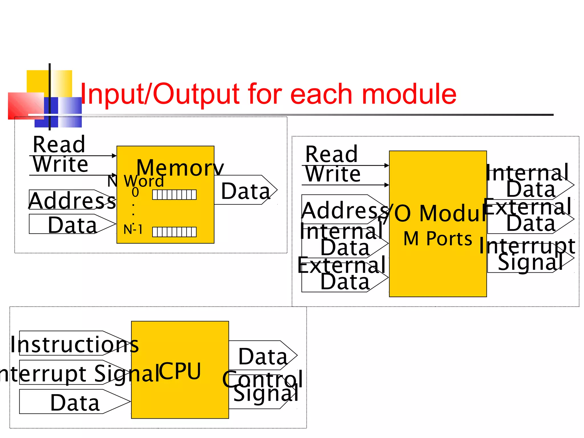
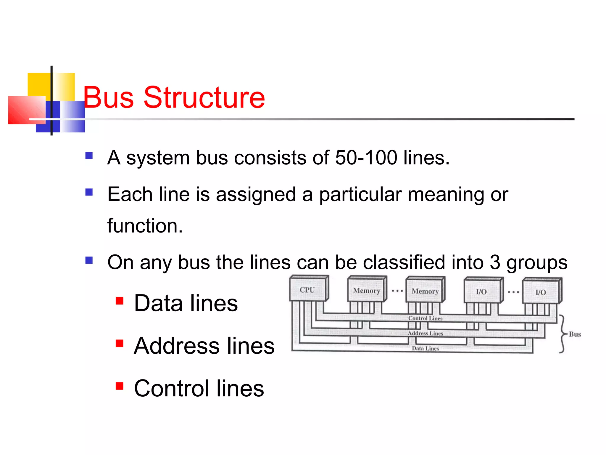
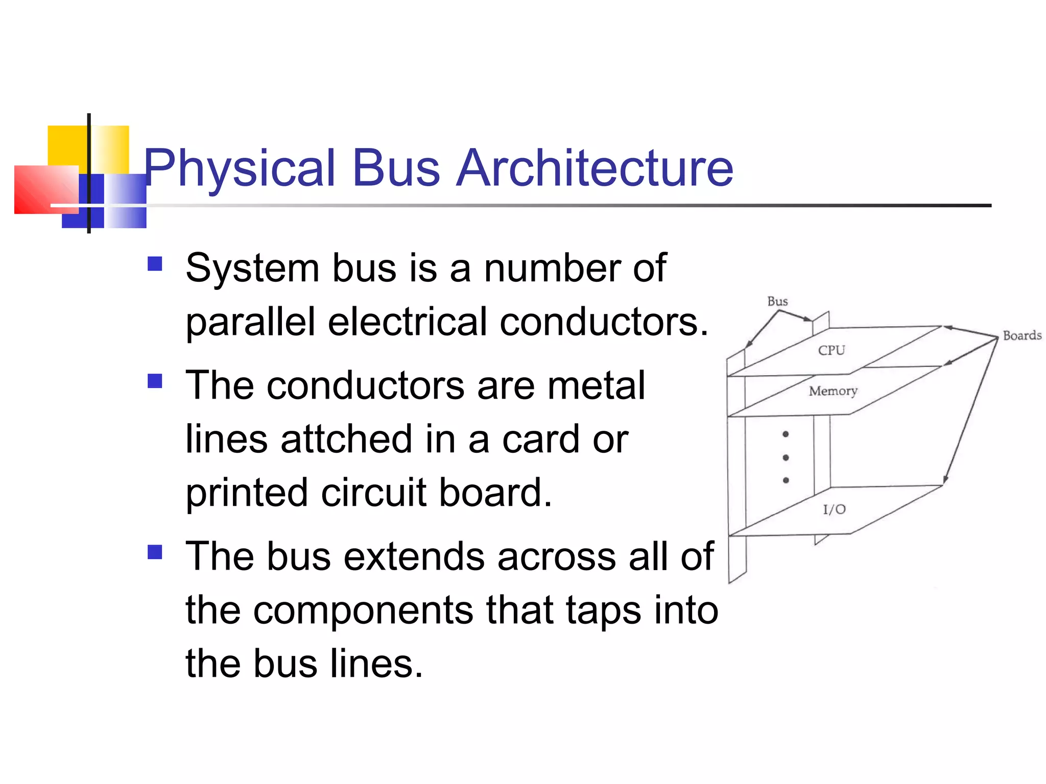
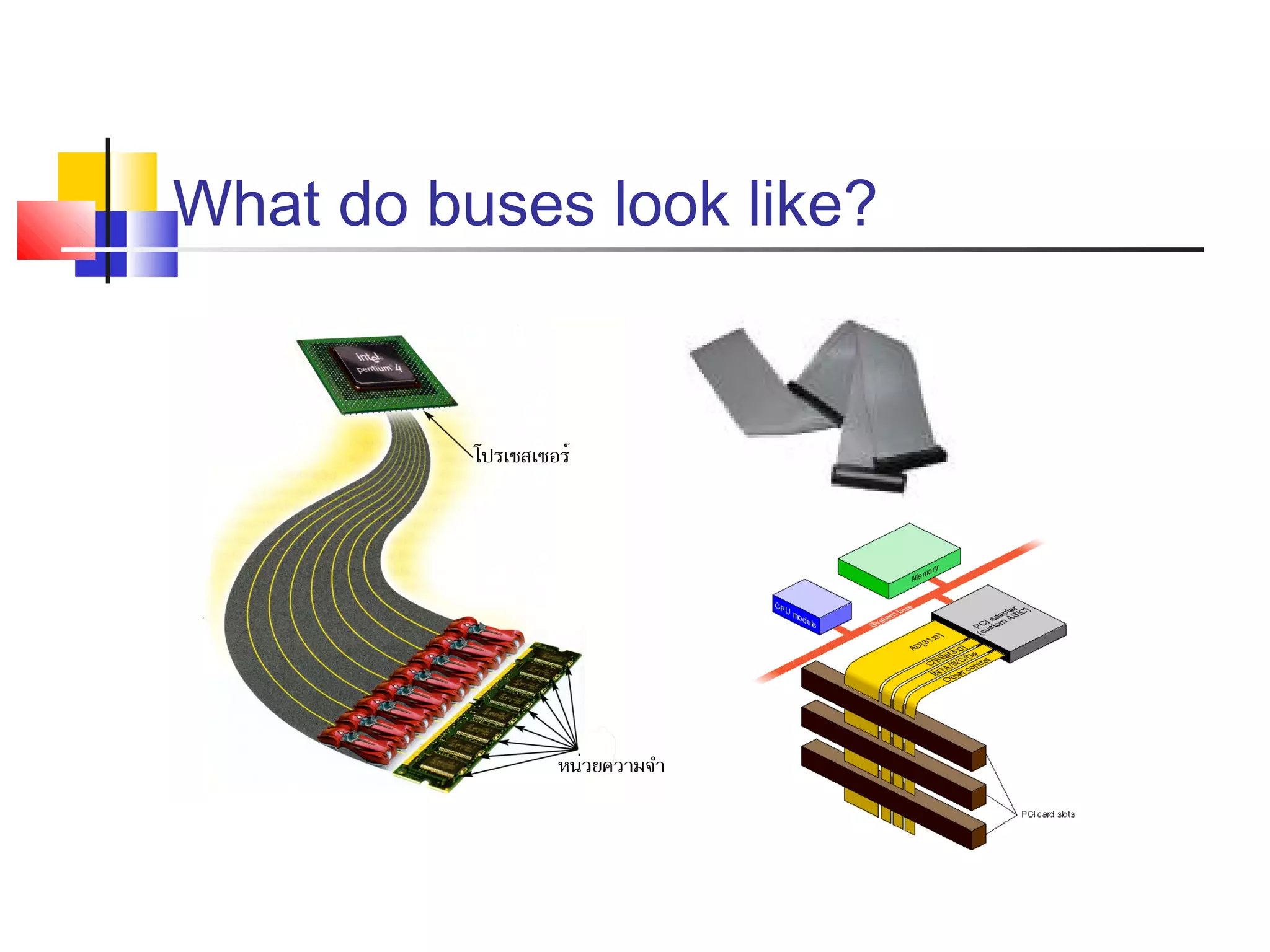
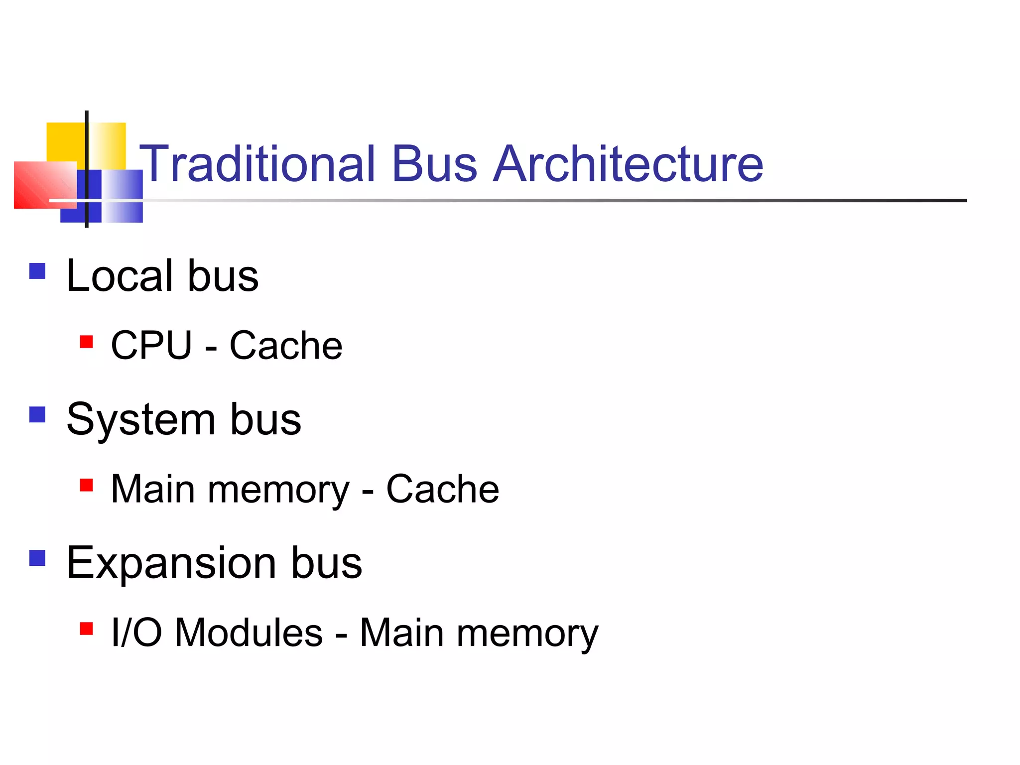
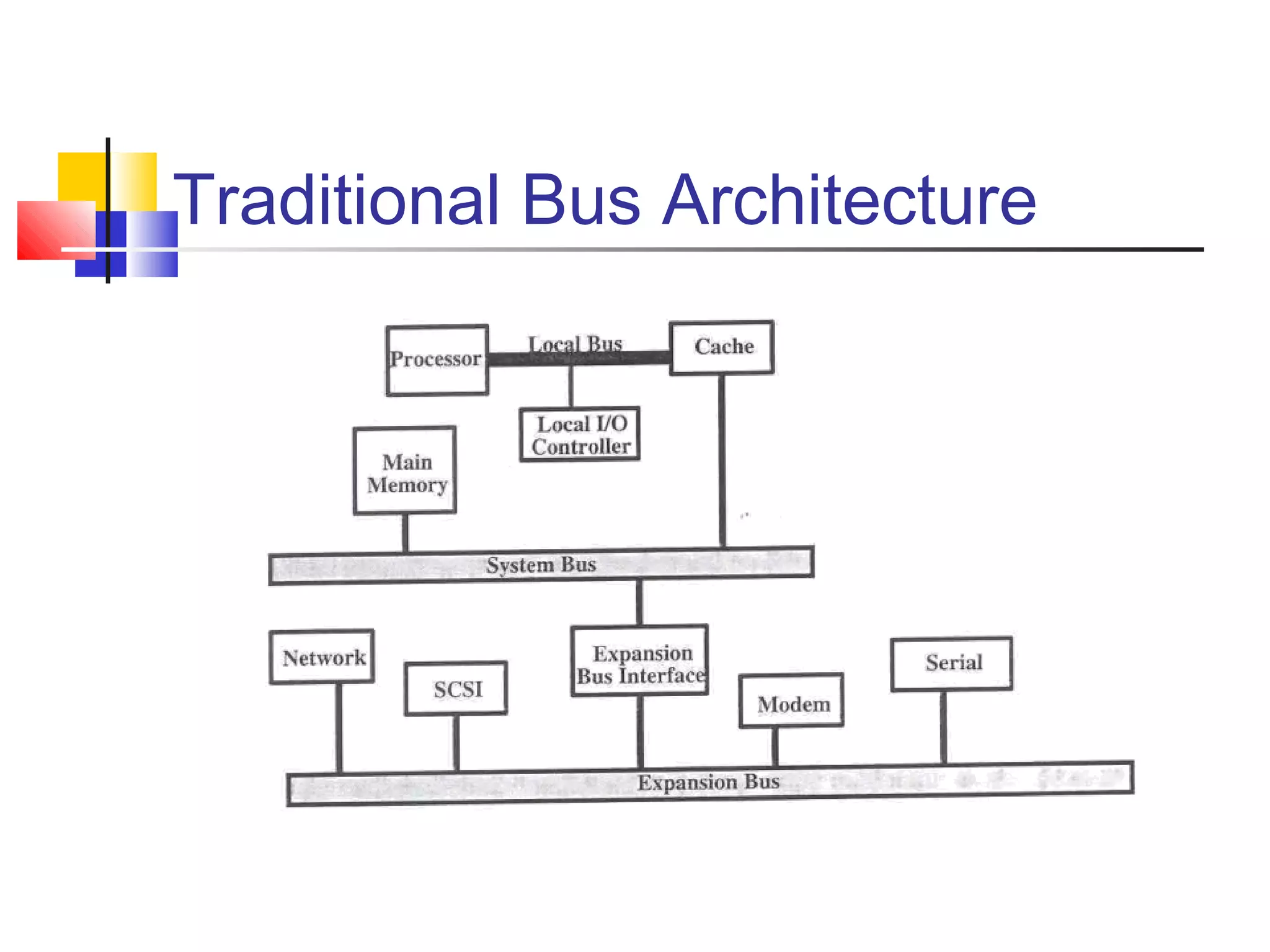
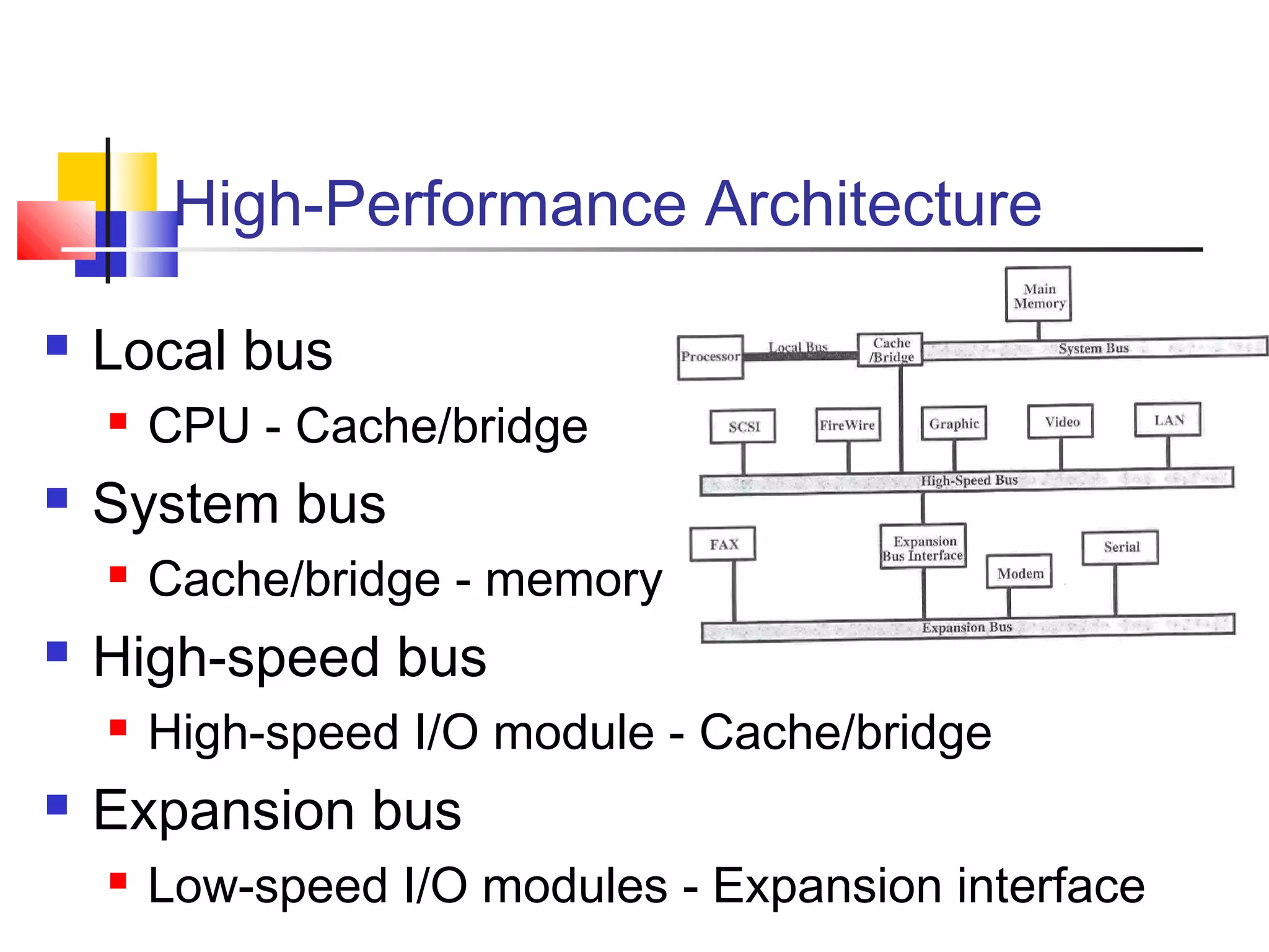
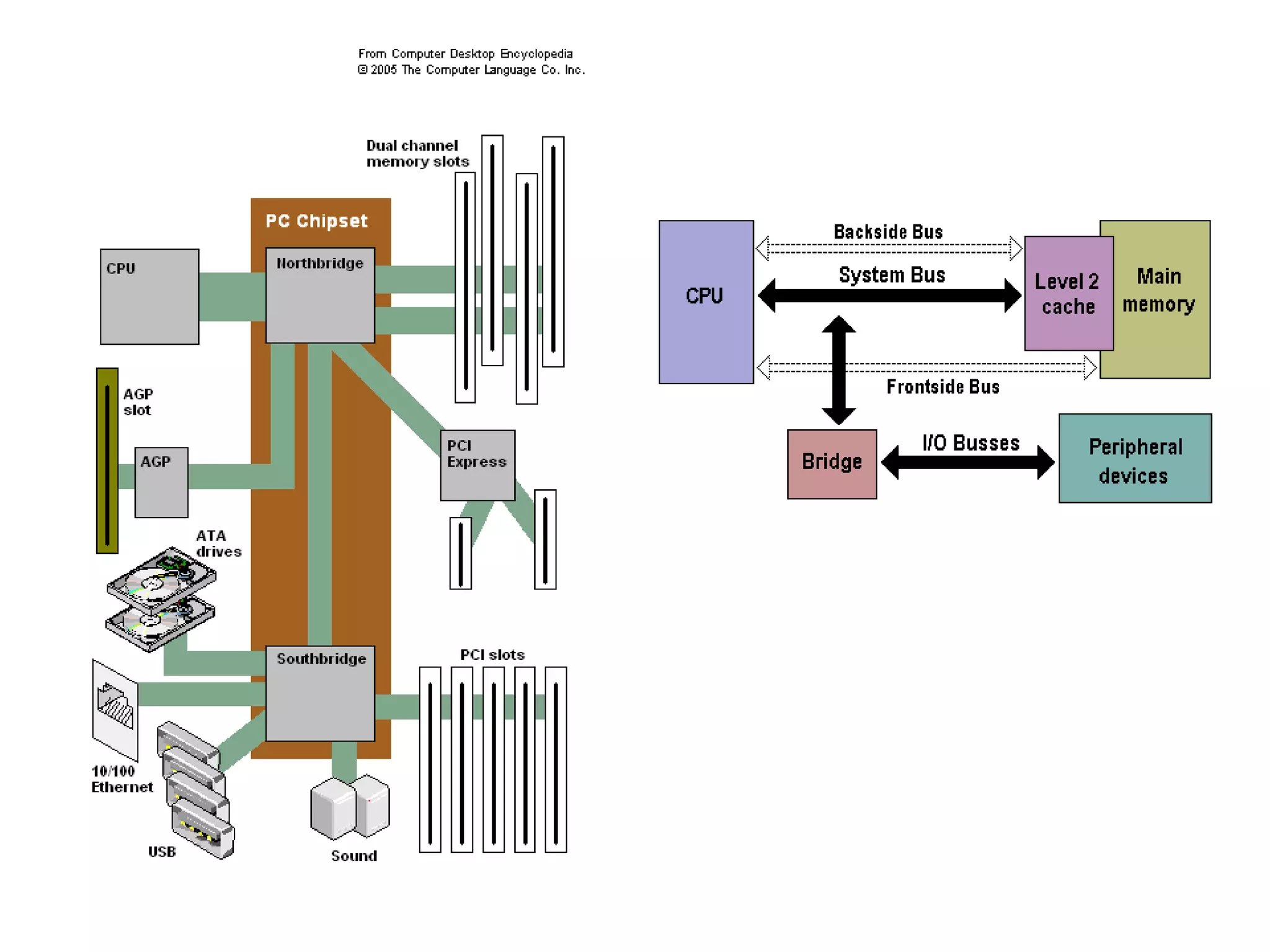
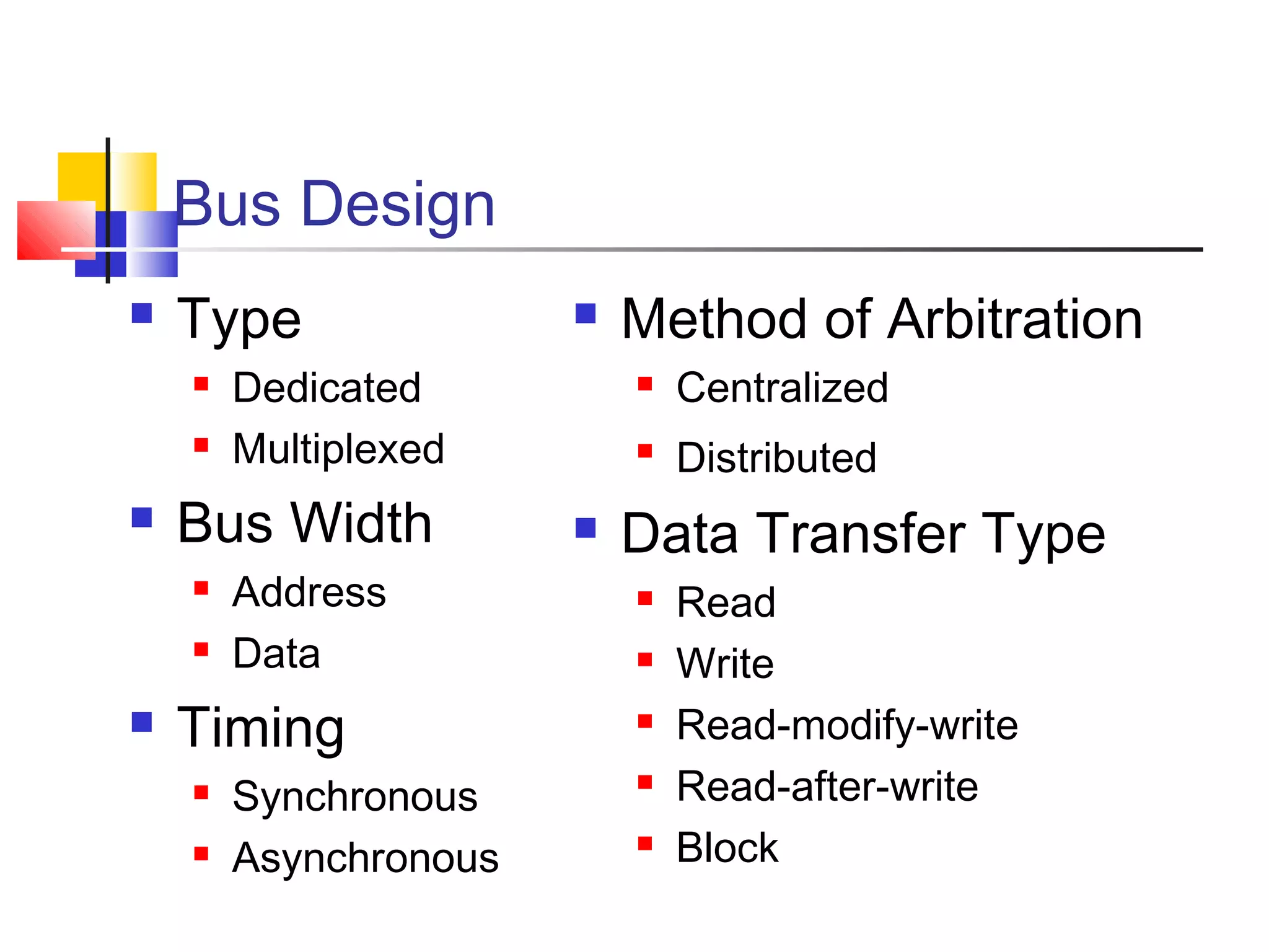

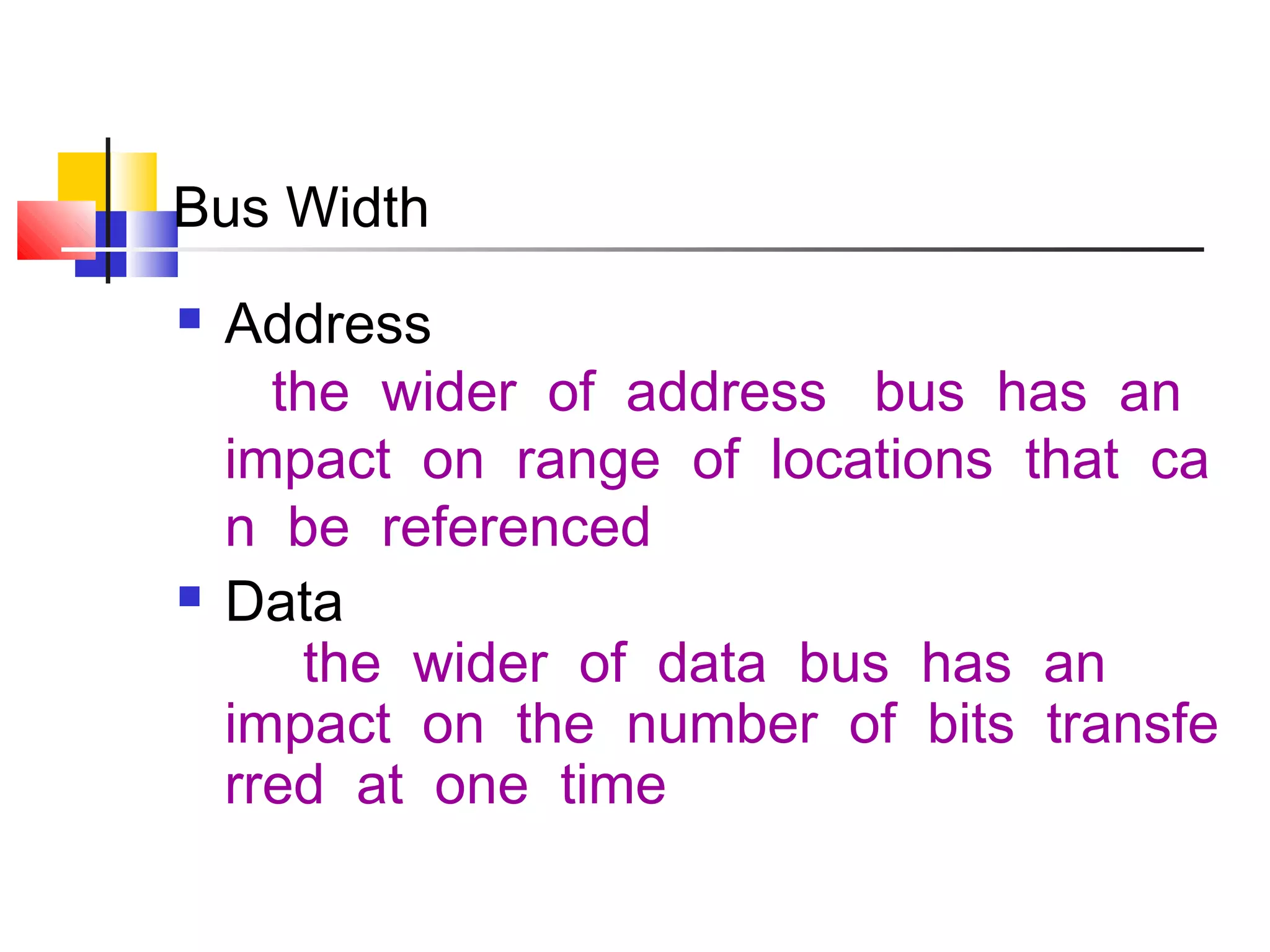

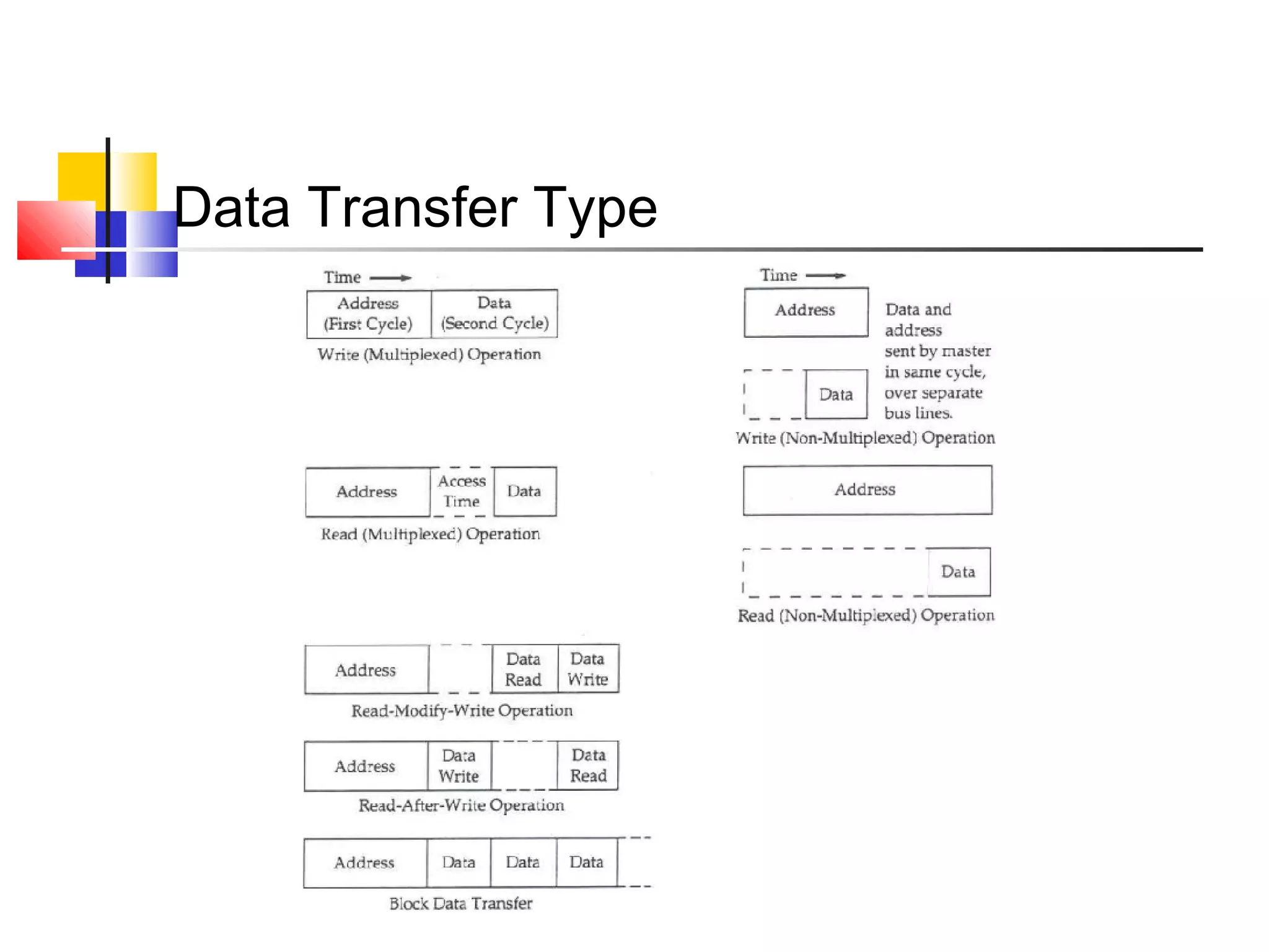

The document discusses bus interconnection in computers. It describes how a bus is a shared communication pathway that connects major components like the CPU, memory and I/O devices. The key parts of a bus are the data lines that transfer information, address lines that specify locations, and control lines that manage access and transfers. Buses can be designed in different ways like dedicated vs multiplexed and vary in aspects such as width, timing, and arbitration method. Common transfer types on a bus include reads, writes, and block transfers.