Downloaded 218 times


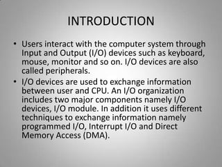
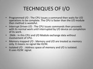
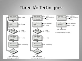
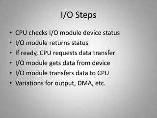
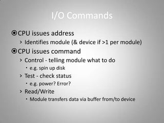
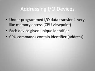
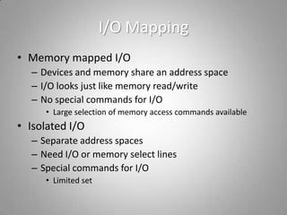
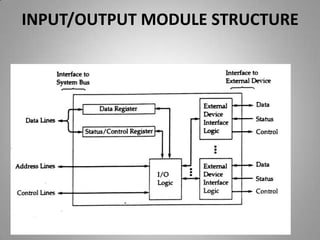
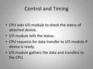
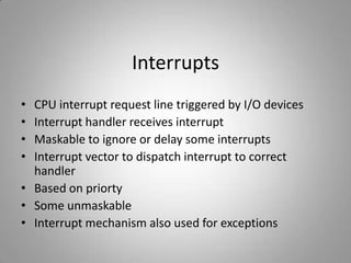
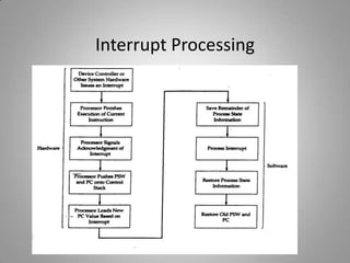
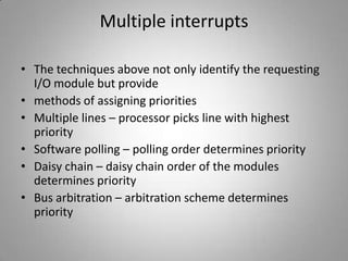
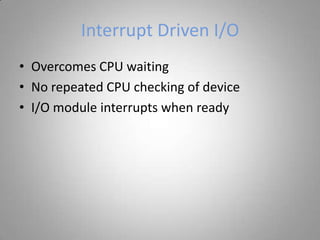
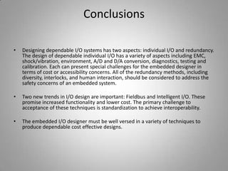


This document discusses different input/output techniques for computer systems. It describes three main I/O techniques: programmed I/O, interrupt-driven I/O, and direct memory access. Programmed I/O involves the CPU waiting for I/O operations to complete, interrupt-driven I/O uses interrupts to notify the CPU when an operation is done, and DMA allows data transfers without CPU involvement. The document also outlines functions of I/O modules, which connect I/O devices to system buses, and different addressing and mapping schemes for I/O devices.