Downloaded 161 times
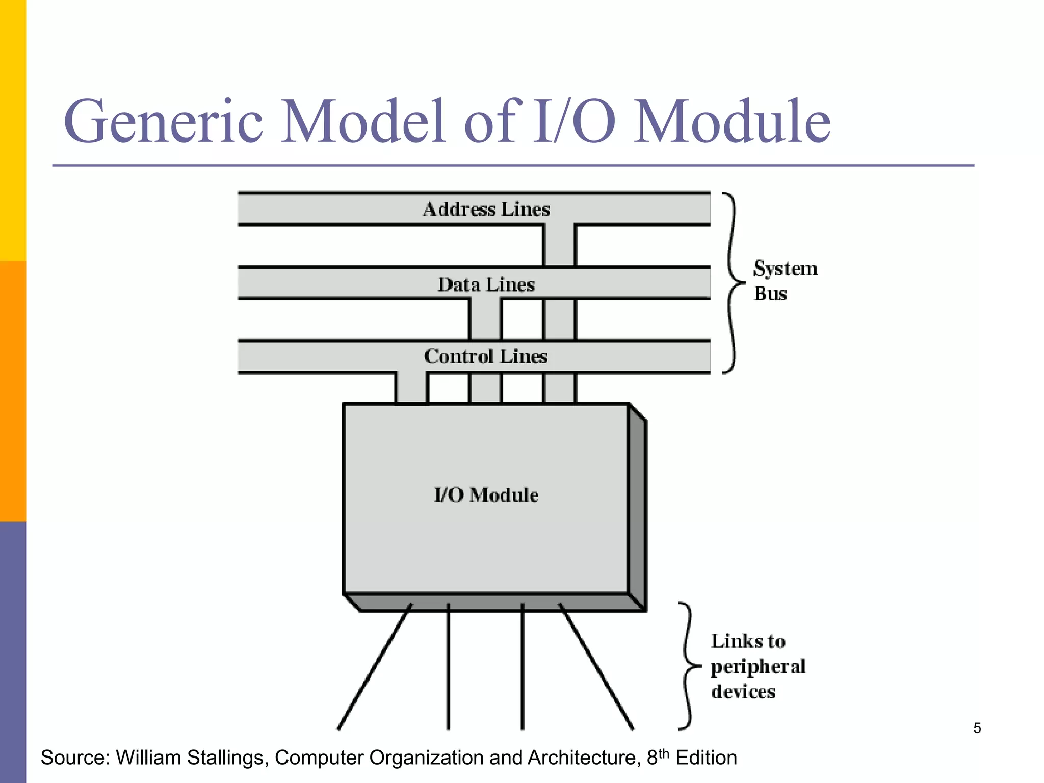
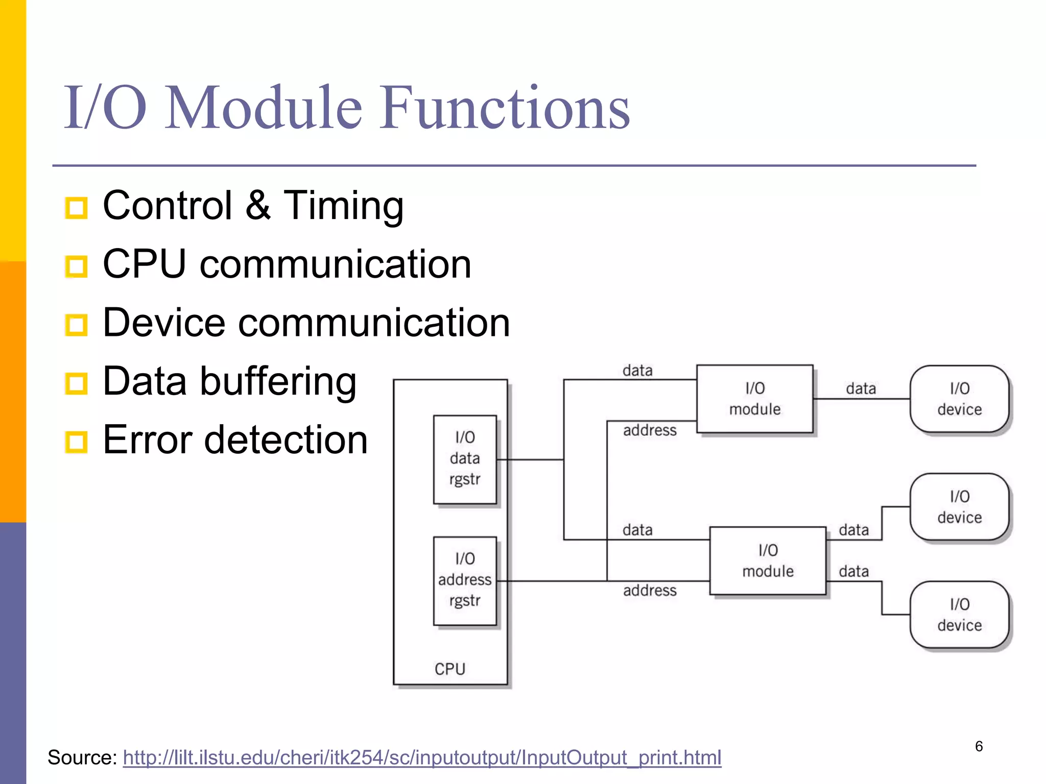
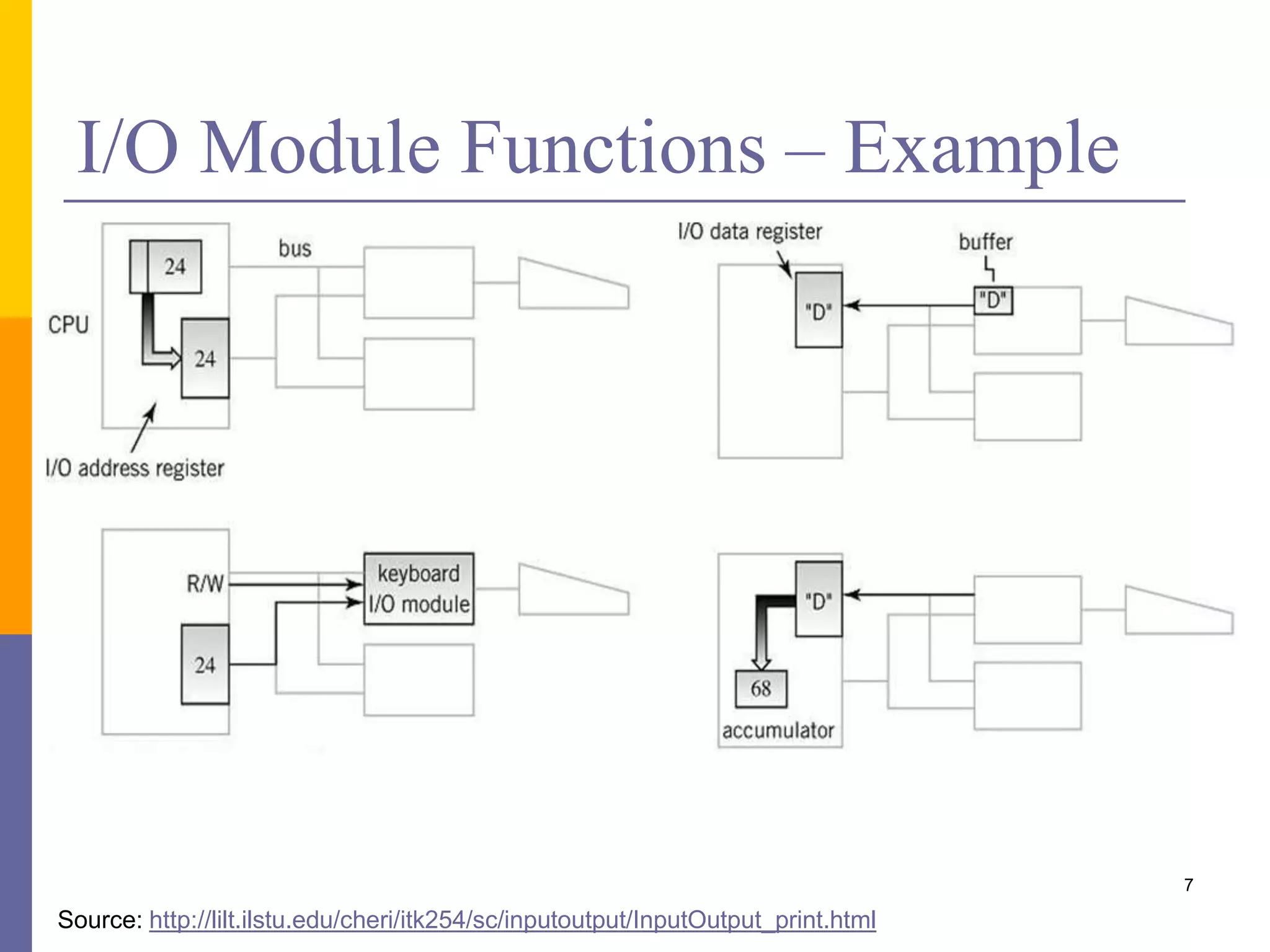
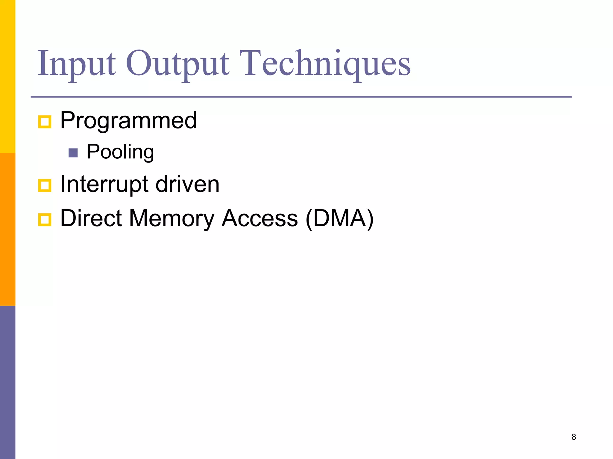
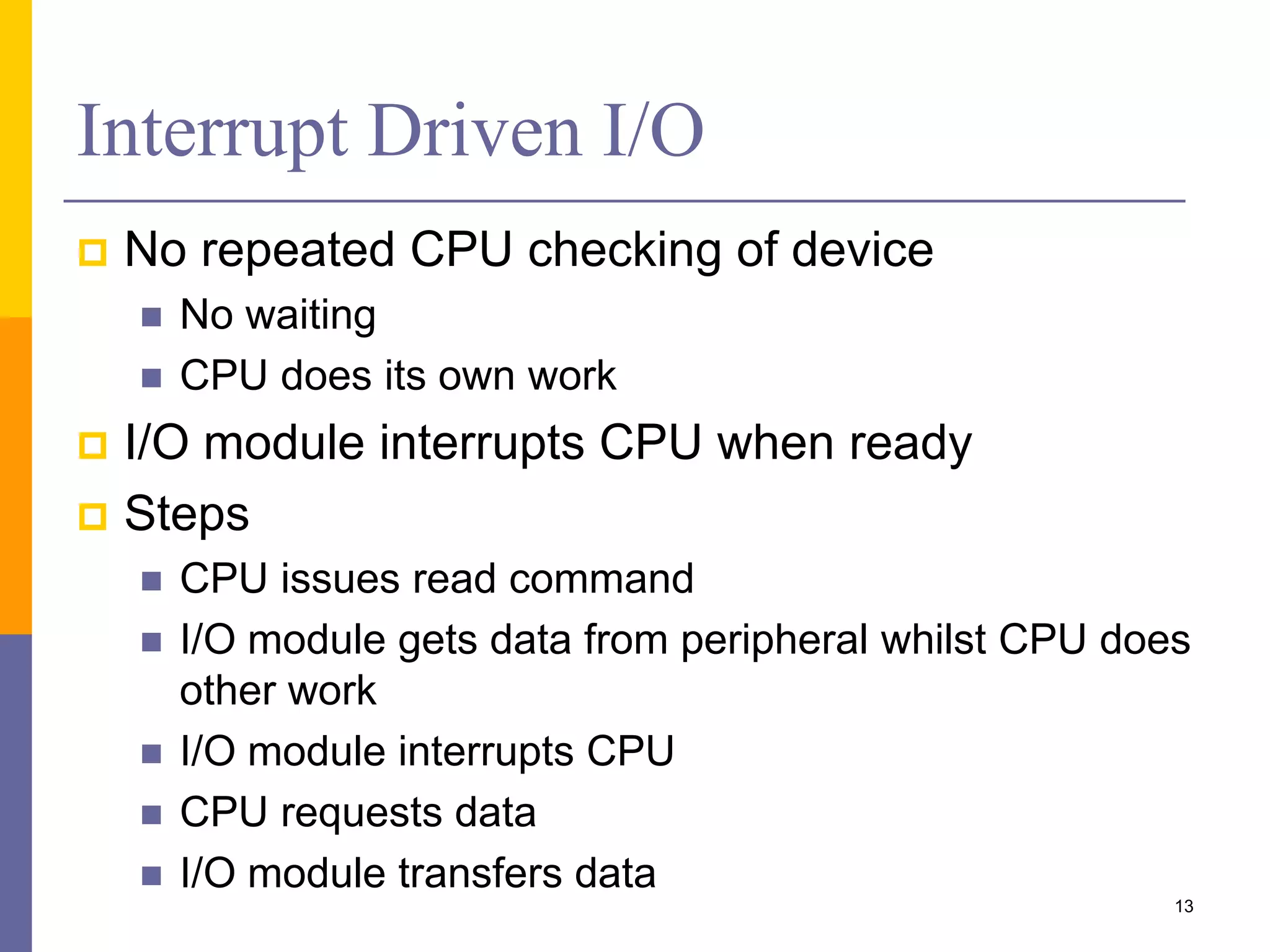
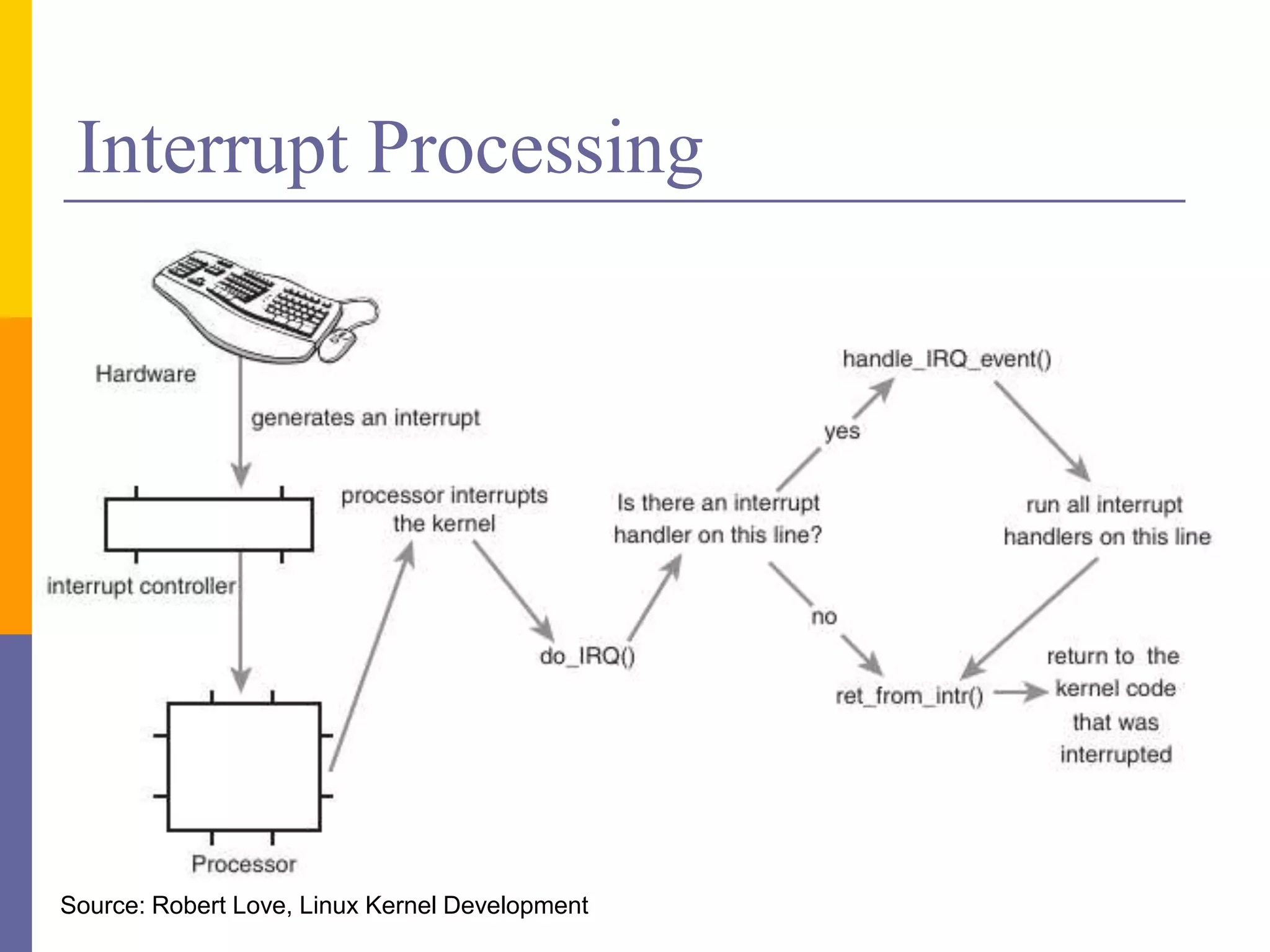
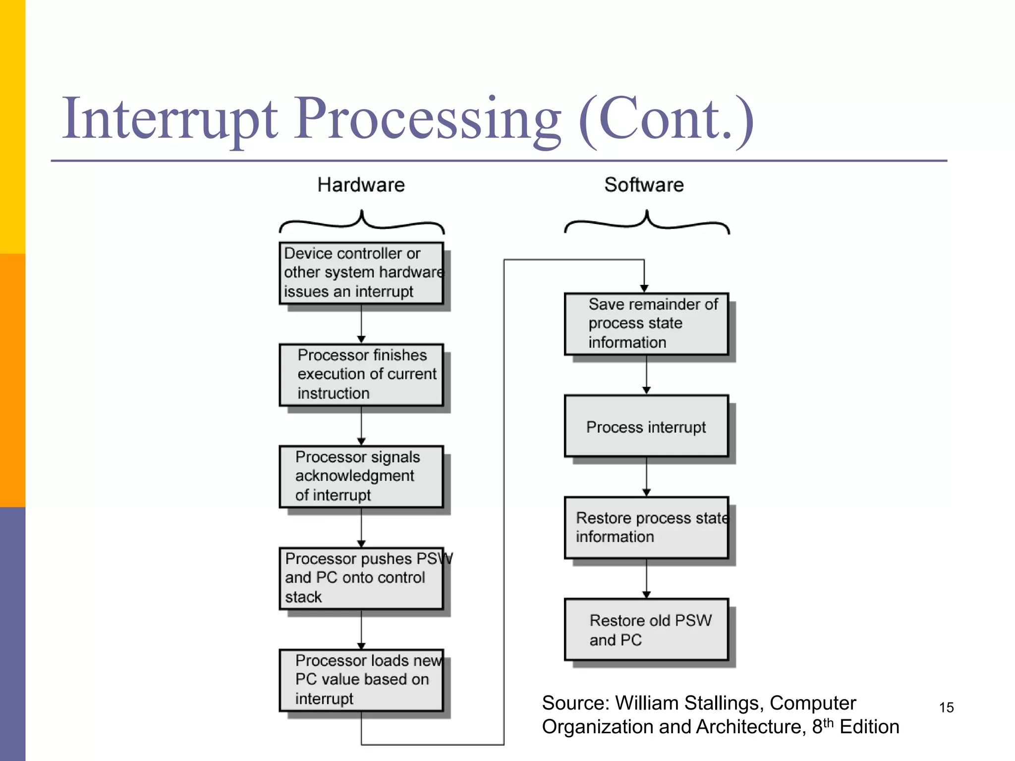
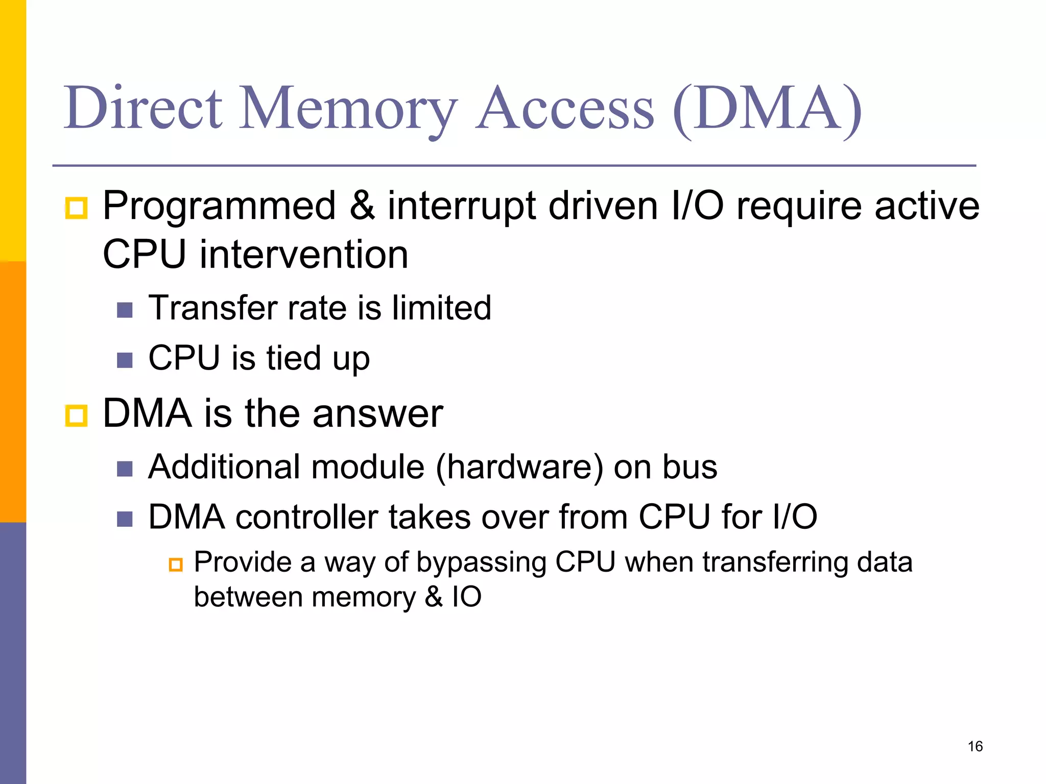
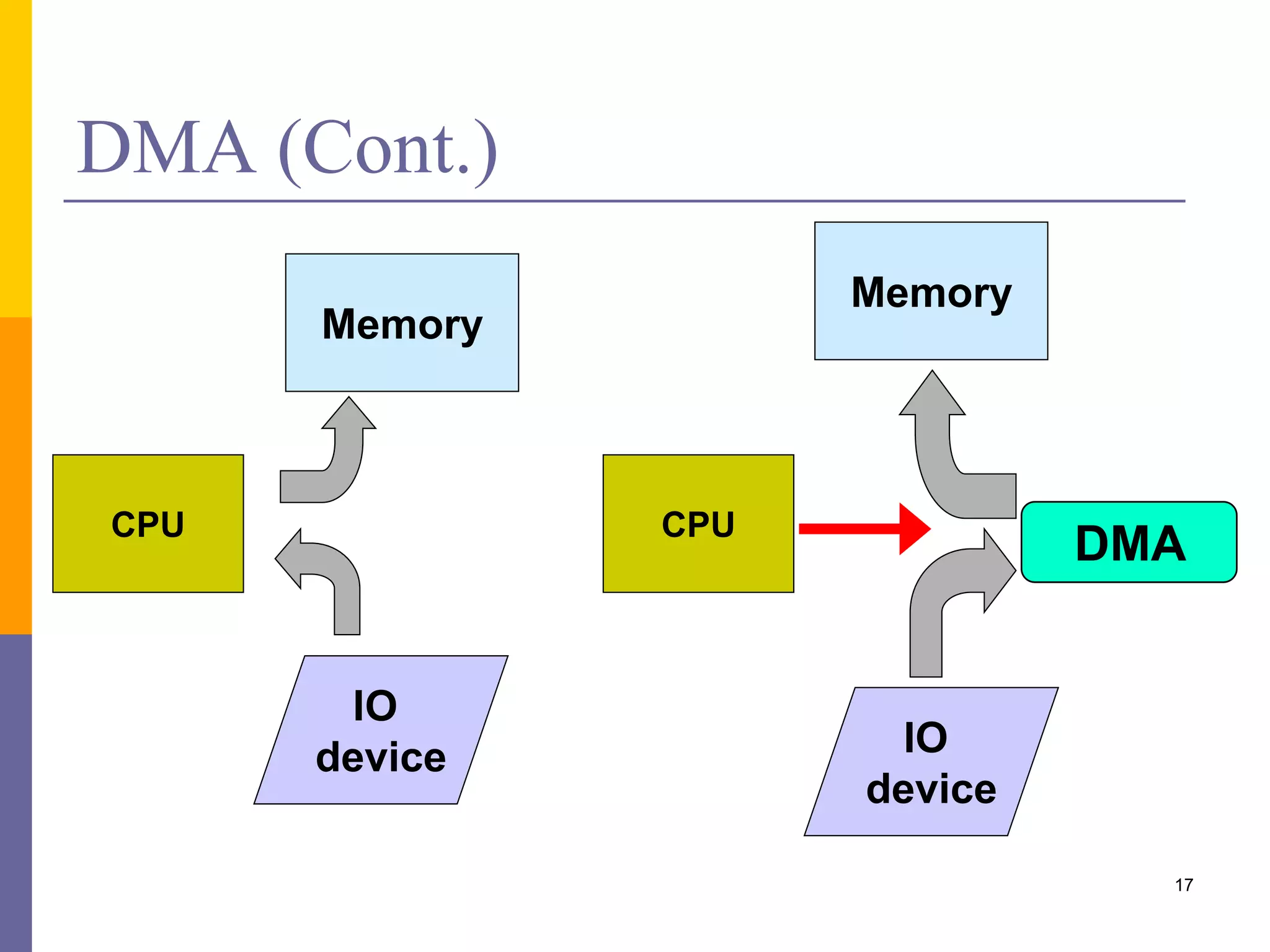
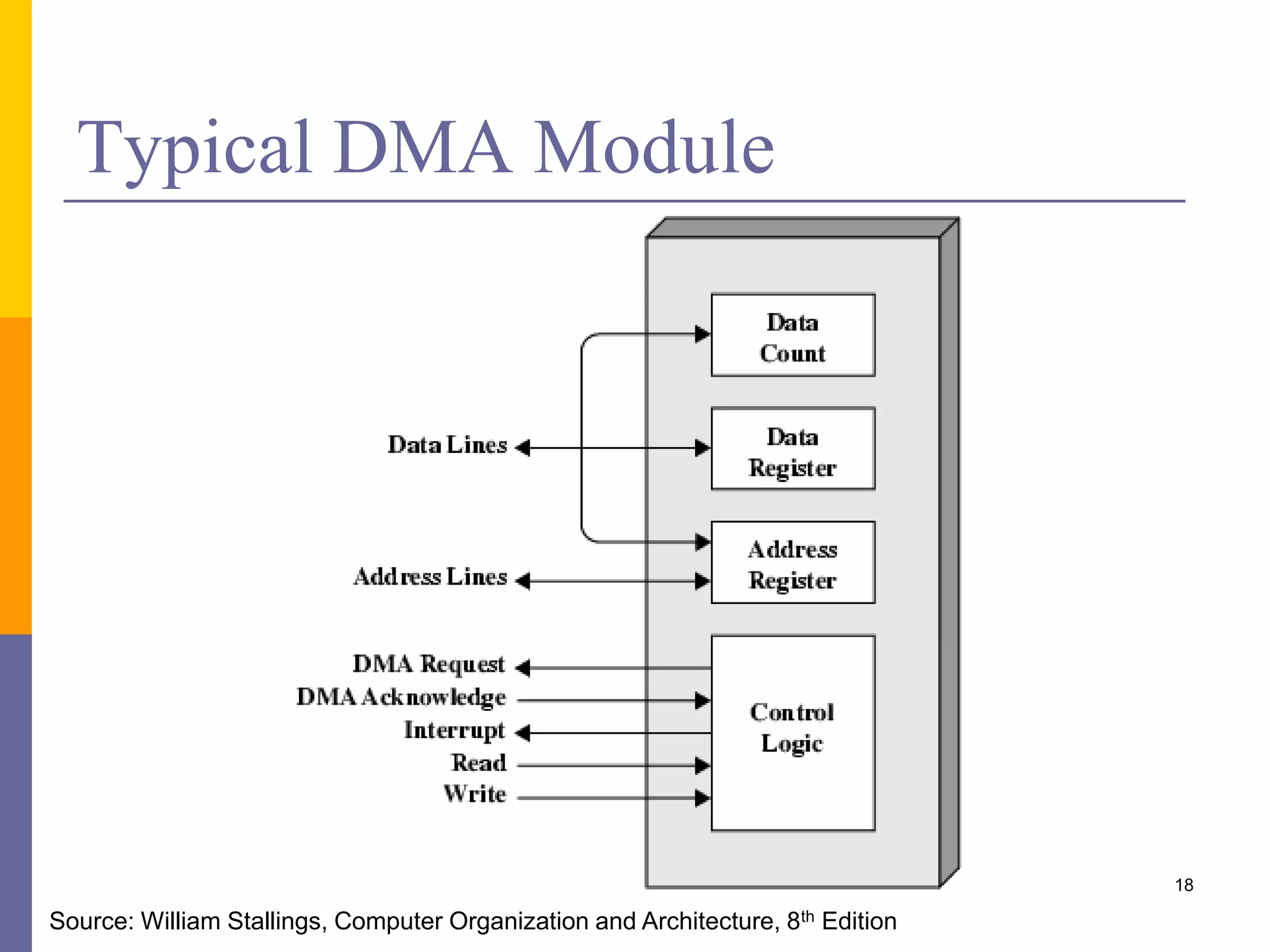
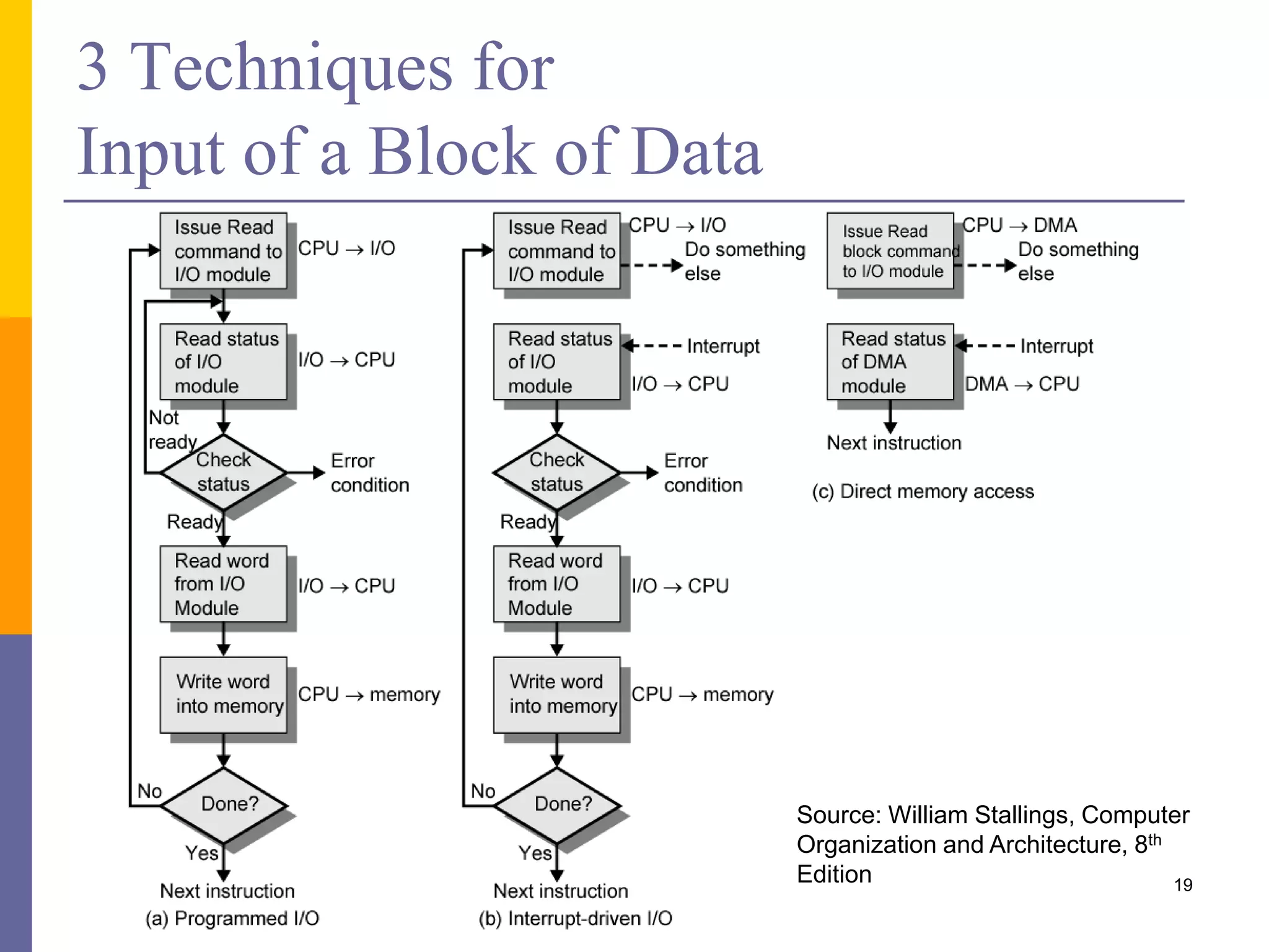

The document discusses input and output in computer systems. It describes three main techniques for transferring data between the CPU and I/O devices: programmed I/O, interrupt-driven I/O, and direct memory access (DMA). Programmed I/O involves the CPU continuously polling I/O devices, interrupt-driven I/O uses interrupts to signal the CPU when data is ready, and DMA allows high-speed transfer of data directly between memory and I/O devices without CPU involvement.