Download to read offline
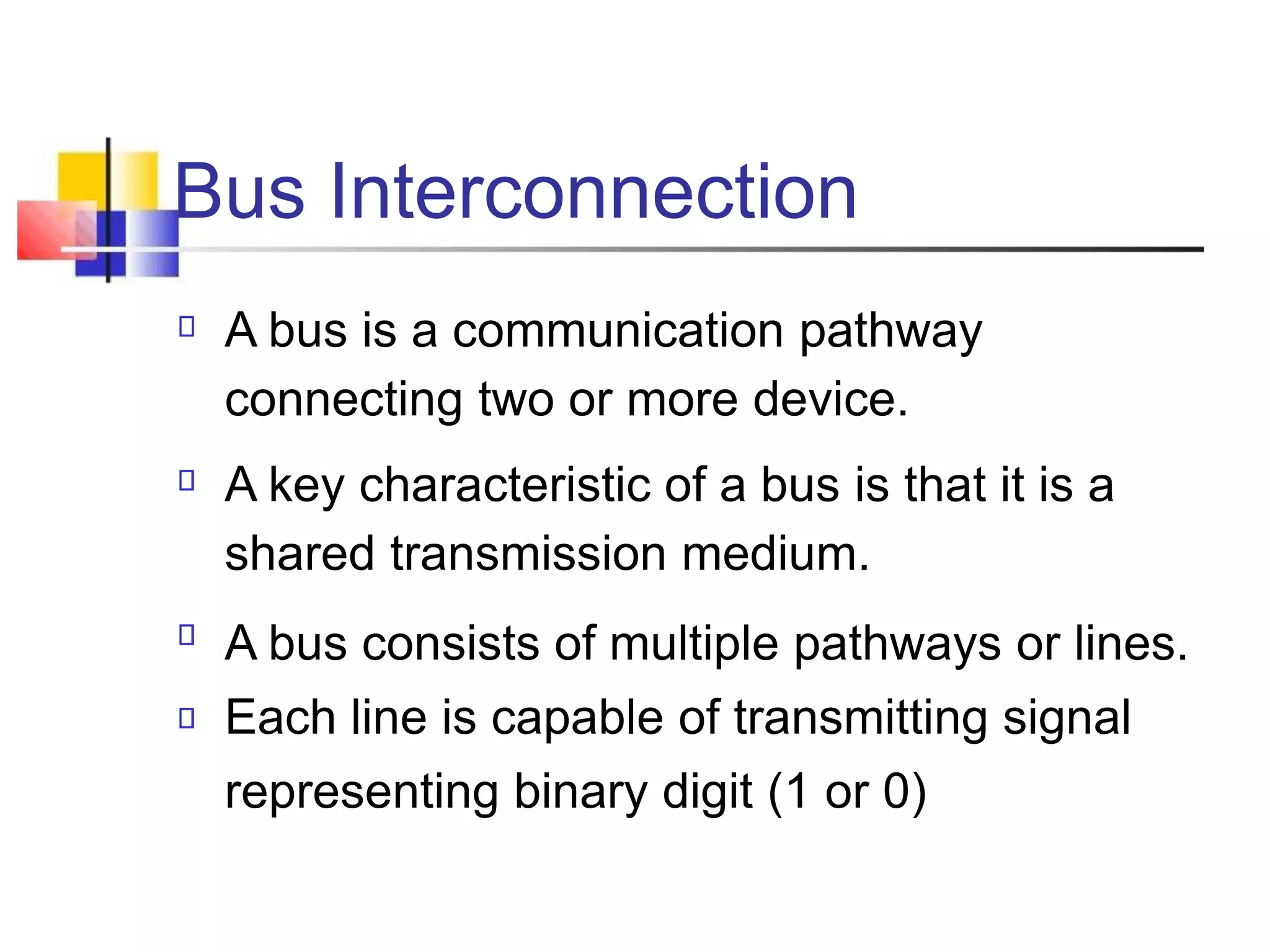
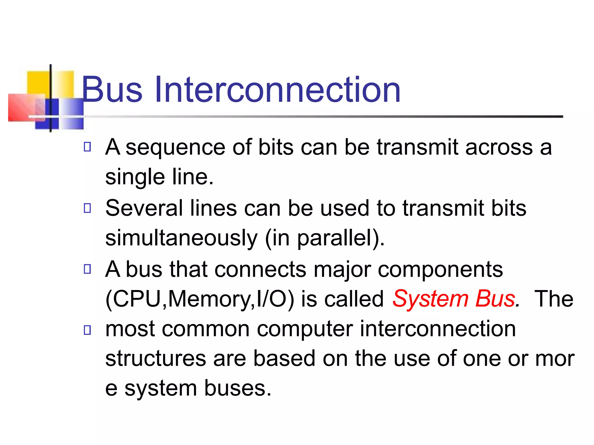
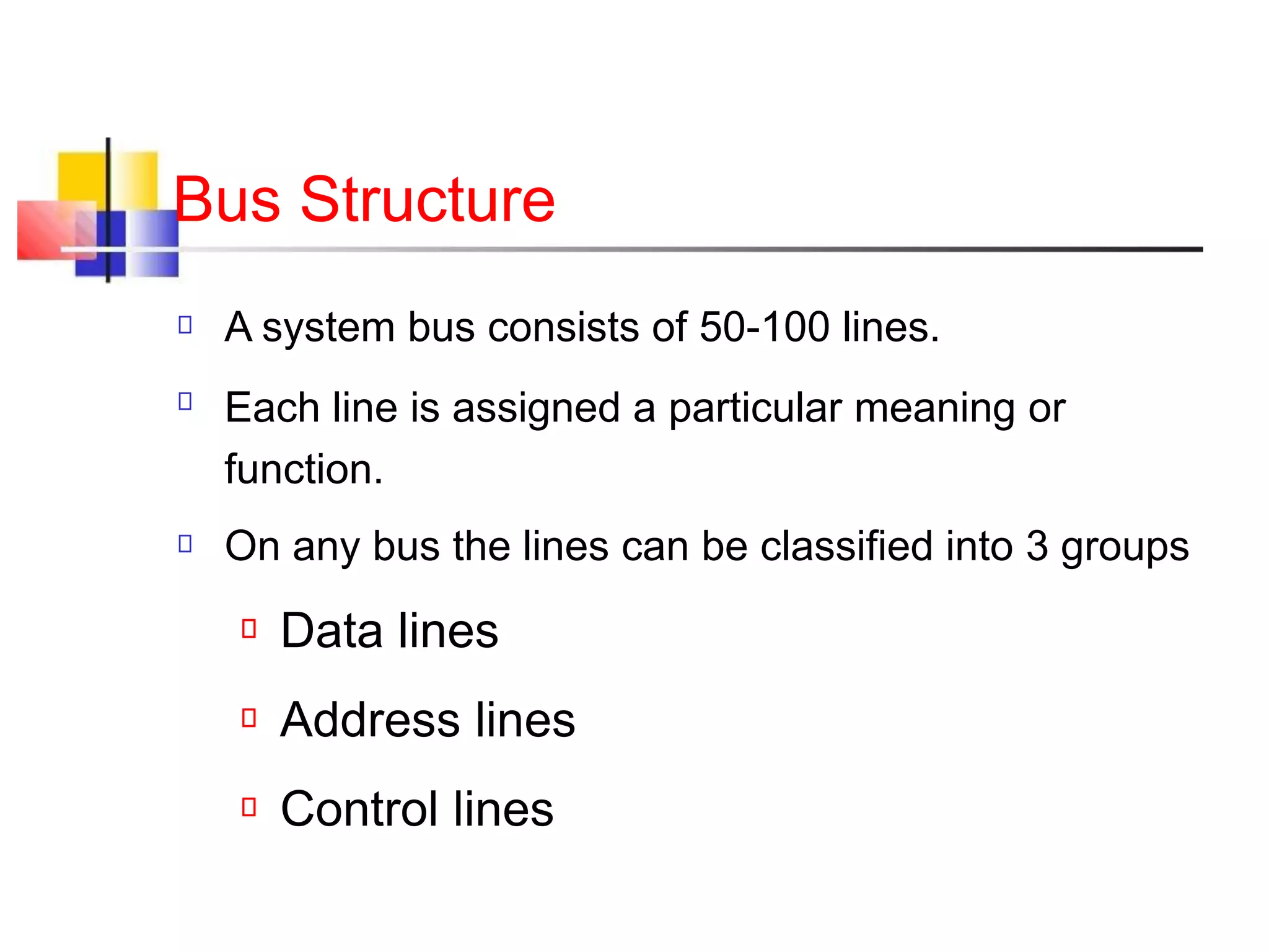
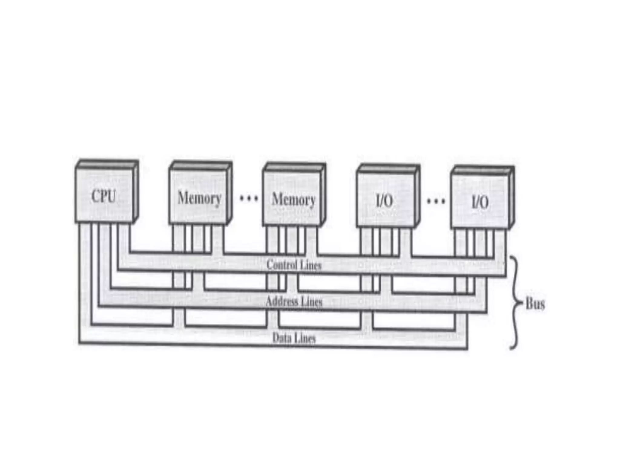

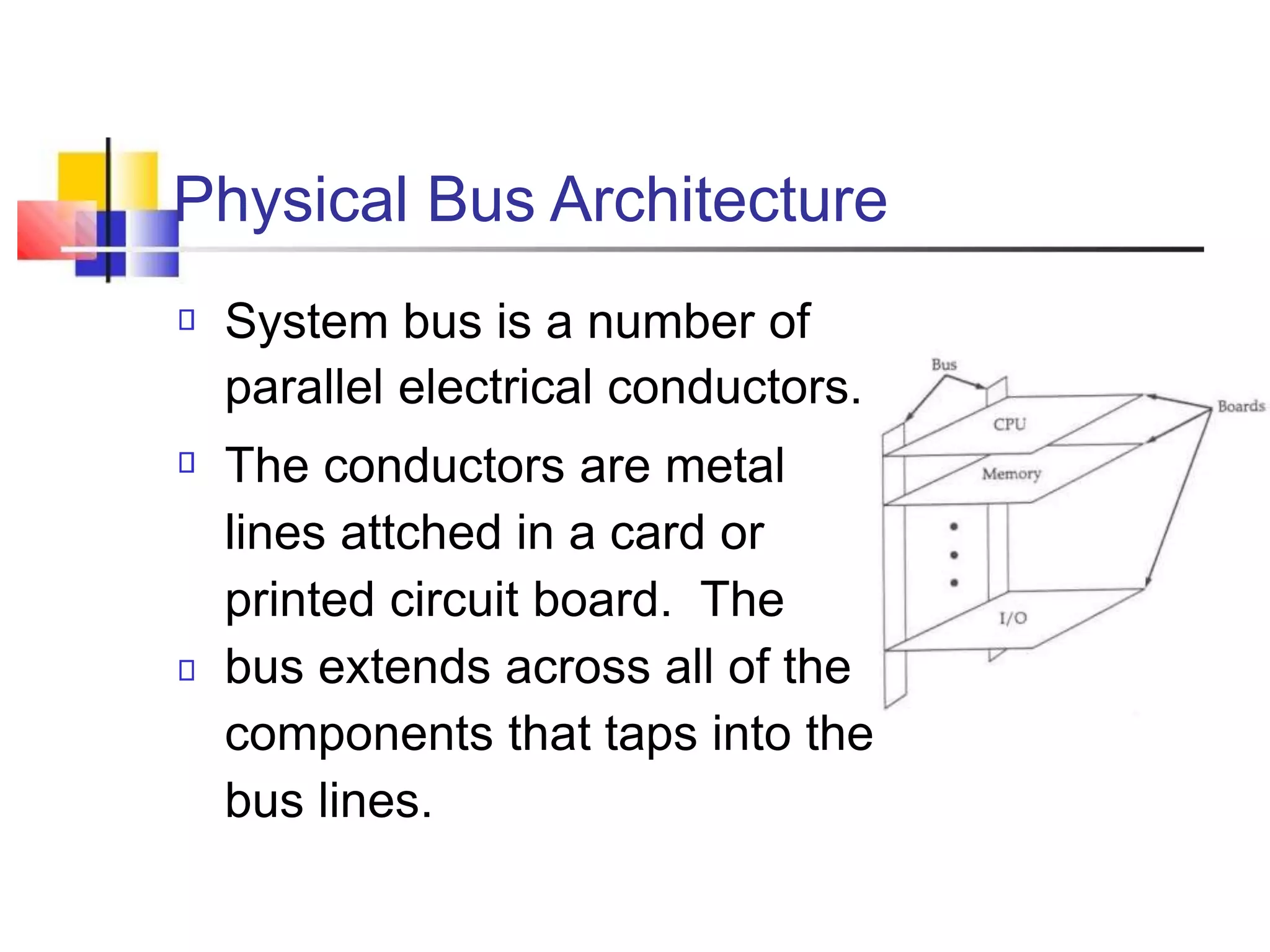
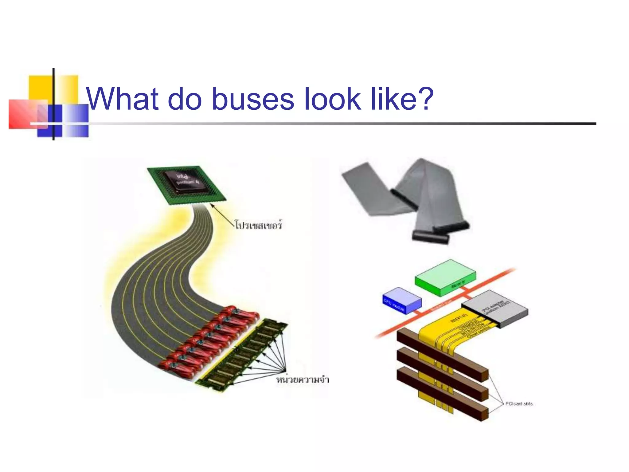
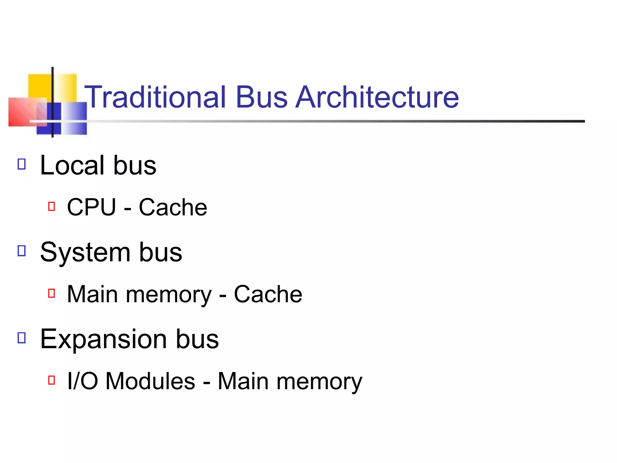
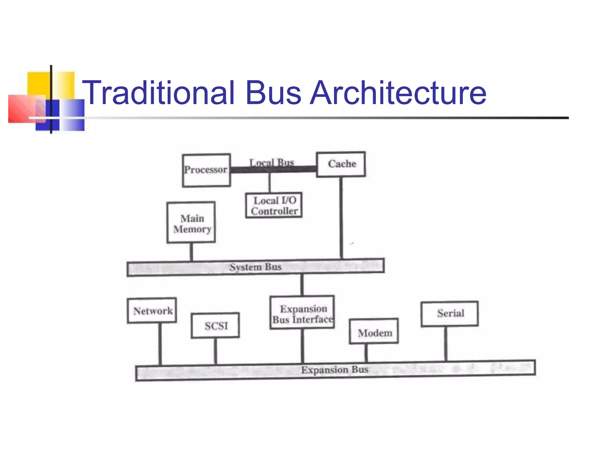
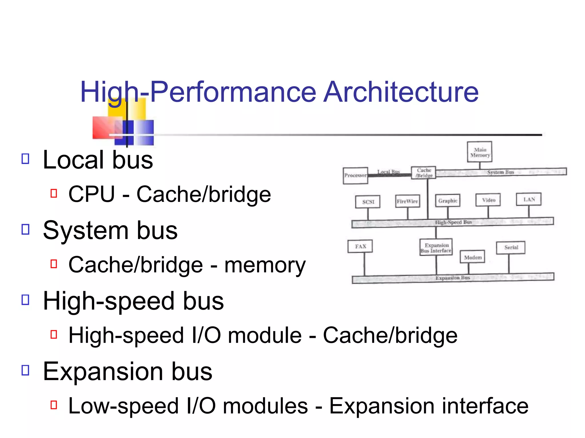
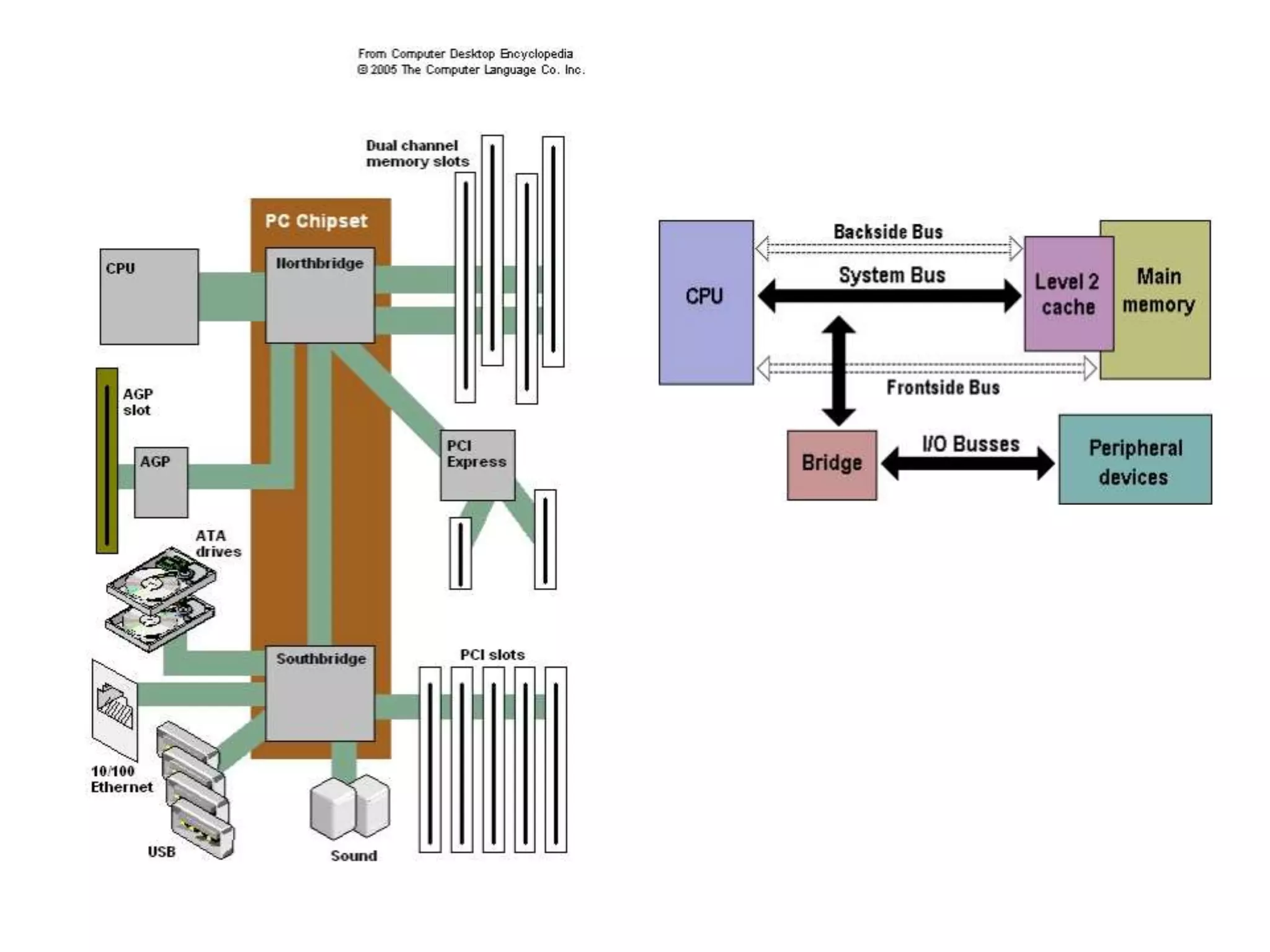
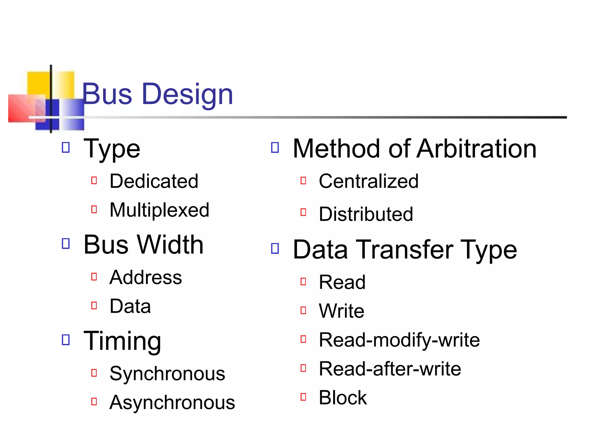
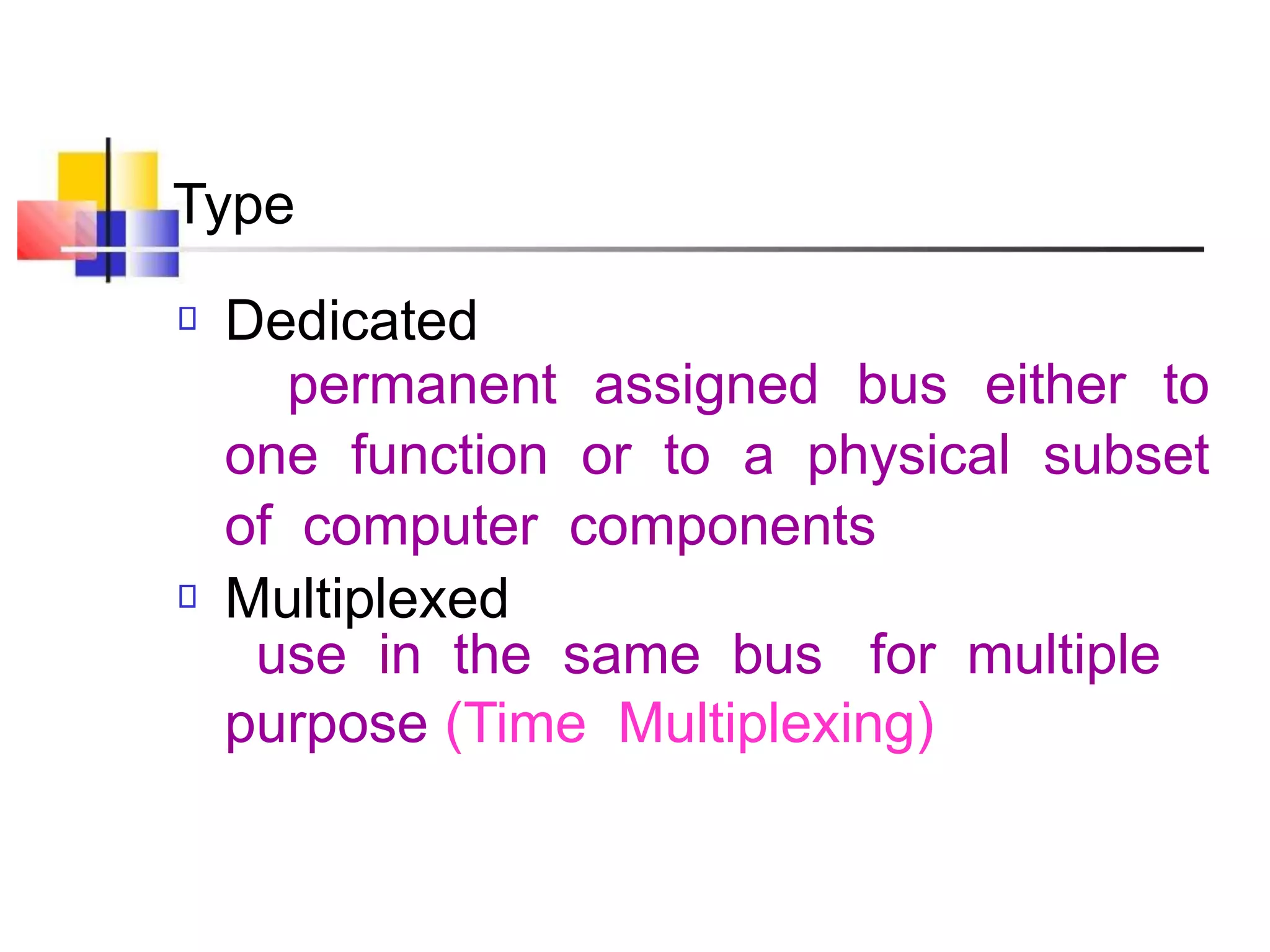

The document discusses bus interconnection structures in computers. A bus is a shared communication pathway that connects central processing units, memory, and input/output devices. It consists of multiple parallel lines for transmitting address, data, and control signals. Common bus architectures include traditional bus designs with local and system buses and higher performance designs with cache/memory bridges and multiple bus types.