Downloaded 58 times


![Syntax
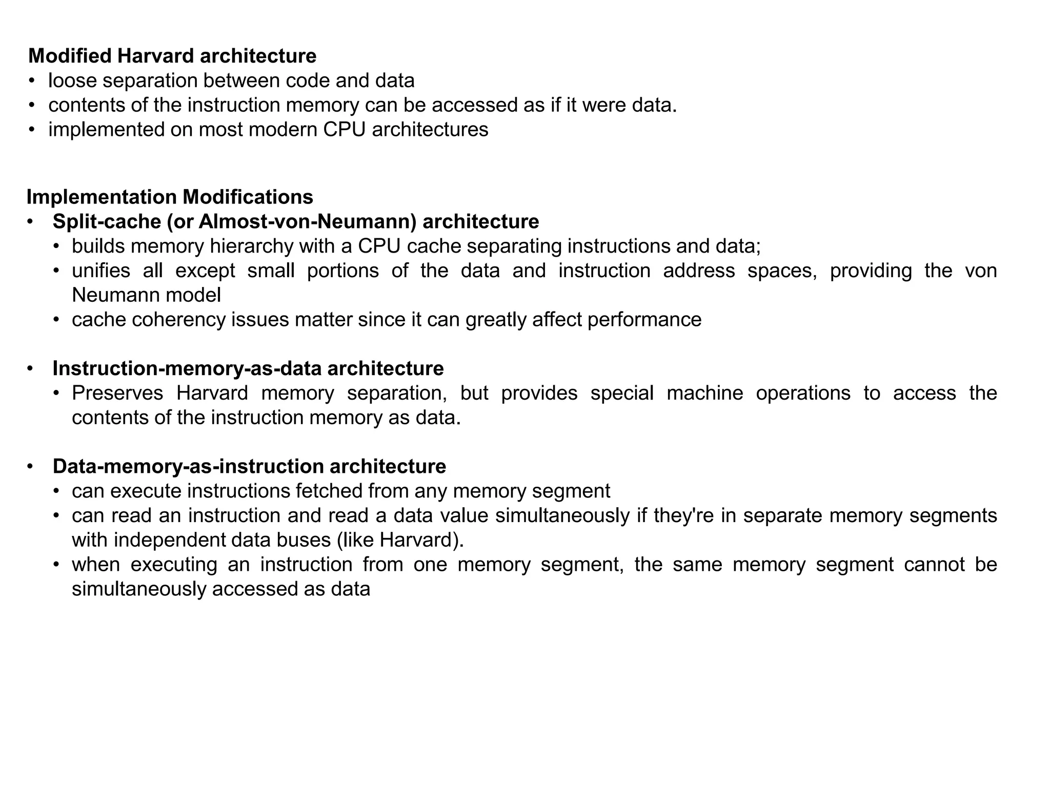
• x86 assembly language has two main syntax branches:
Intel syntax, originally used for documentation of the x86 platform and is dominant in the MS-DOS and
Windows world (Many x86 assemblers use Intel syntax, including NASM, FASM, MASM, TASM, and YASM)
AT&T syntax is dominant in the Unix world, since Unix was created at AT&T Bell Labs
Summary of the main differences between Intel syntax and AT&T syntax:
AT&T Intel
Parameter
order
Source before the destination.
mov $5, %eax
Destination before source.
mov eax, 5
Parameter
size
Mnemonics are suffixed with a letter
indicating the size of the operands: q for
qword, l for long (dword), w for word, and b
for byte.
addl $4, %esp
Derived from the name of the register that is
used (e.g. rax, eax, ax, al imply q, l, w, b,
respectively).
add esp, 4
Sigils
Immediate values prefixed with a "$",
registers prefixed with a "%".
The assembler automatically detects the type of
symbols; i.e., whether they are registers,
constants or something else.
Effective
addresses
General syntax of
DISP(BASE,INDEX,SCALE).
Example:
movl mem_location(%ebx,%ecx,4), %eax
Arithmetic expressions in square brackets;
additionally, size keywords like byte, word, or
dword have to be used if the size cannot be
determined from the operands.
Example:
mov eax, [ebx + ecx*4 + mem_location]](https://image.slidesharecdn.com/x86-170930140800/75/x86-architecture-18-2048.jpg)


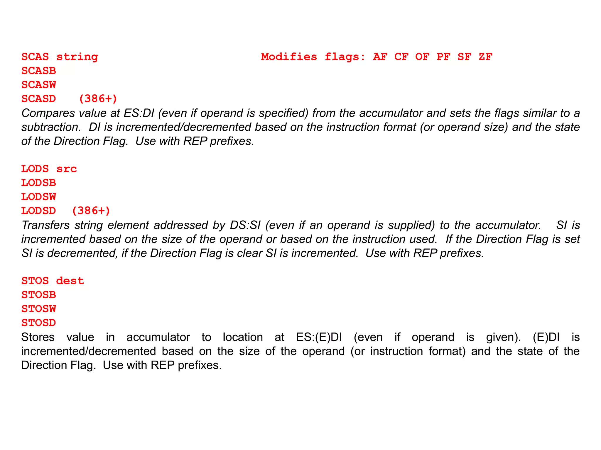
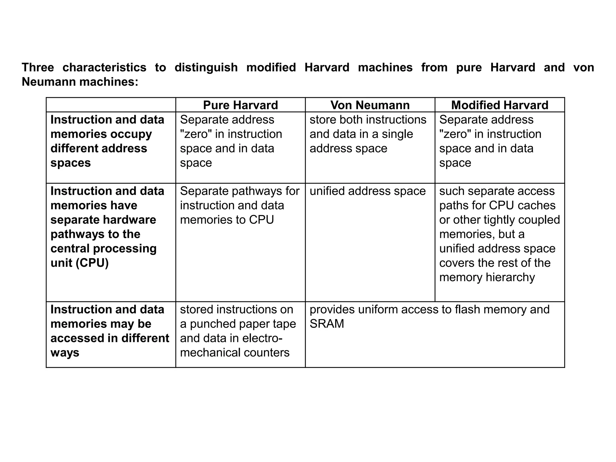
![REP
Repeats execution of string instructions while CX != 0. After each string operation, CX is decremented and
the Zero Flag is tested. The combination of a repeat prefix and a segment override on CPU's before the 386
may result in errors if an interrupt occurs before CX=0. The following code shows code that is susceptible to
this and how to avoid it:
again: rep movs byte ptr ES:[DI],ES:[SI] ; vulnerable instr.
jcxz next ; continue if REP successful
loop again ; interrupt goofed count
next:
REPE
REPZ
Repeats execution of string instructions while CX != 0 and the Zero Flag is set. CX is decremented and the
Zero Flag tested after each string operation. The combination of a repeat prefix and a segment override on
processors other than the 386 may result in errors if an interrupt occurs before CX=0.
REPNE
REPNZ
Repeats execution of string instructions while CX != 0 and the Zero Flag is clear. CX is decremented and
the Zero Flag tested after each string operation. The combination of a repeat prefix and a segment override
on processors other than the 386 may result in errors if an interrupt occurs before CX=0.](https://image.slidesharecdn.com/x86-170930140800/75/x86-architecture-32-2048.jpg)


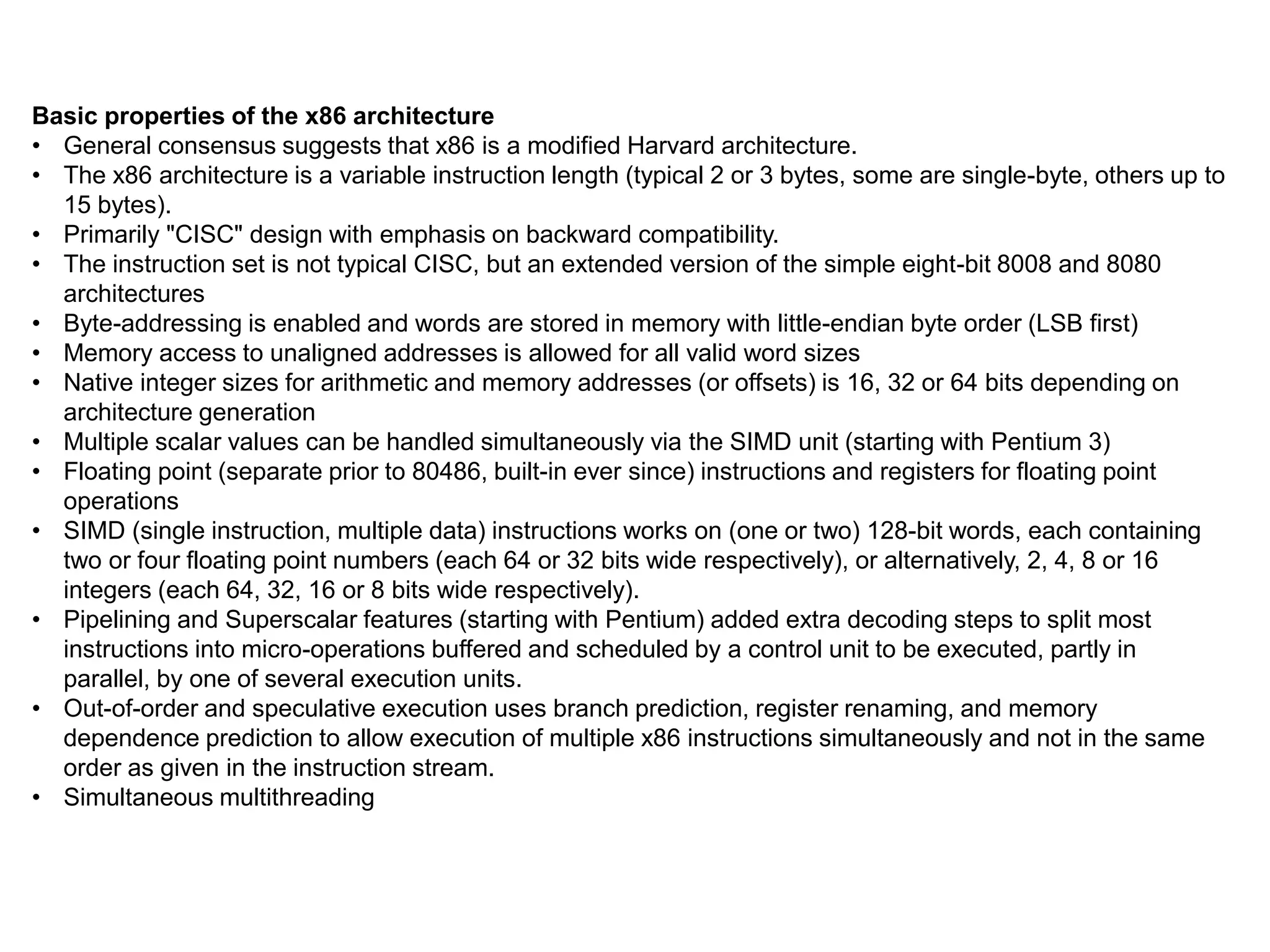
![Miscellaneous Instructions
The miscellaneous instructions provide such functions as loading an effective address, executing a “no-
operation,” and retrieving processor identification information.
NOP
This is a do nothing instruction. It results in occupation of both space and time and is most useful for
patching code segments. (This is the original XCHG AL,AL instruction)
XLAT translation-table
XLATB (masm 5.x)
Replaces the byte in AL with byte from a user table addressed by BX. The original value of AL is the index
into the translate table. The best way to discripe this is MOV AL,[BX+AL]
CPUID
Processor Identification](https://image.slidesharecdn.com/x86-170930140800/75/x86-architecture-39-2048.jpg)


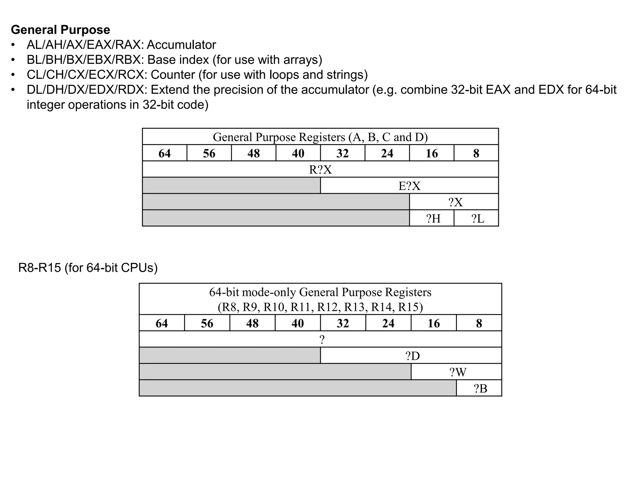
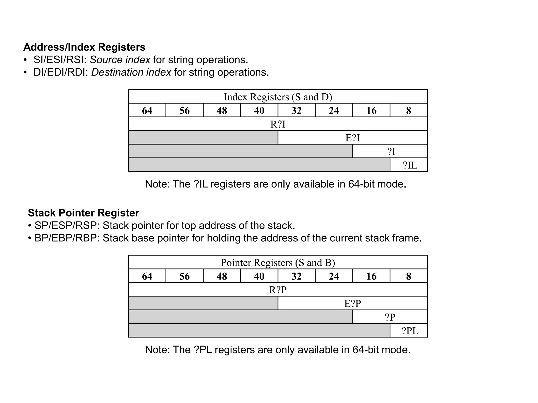
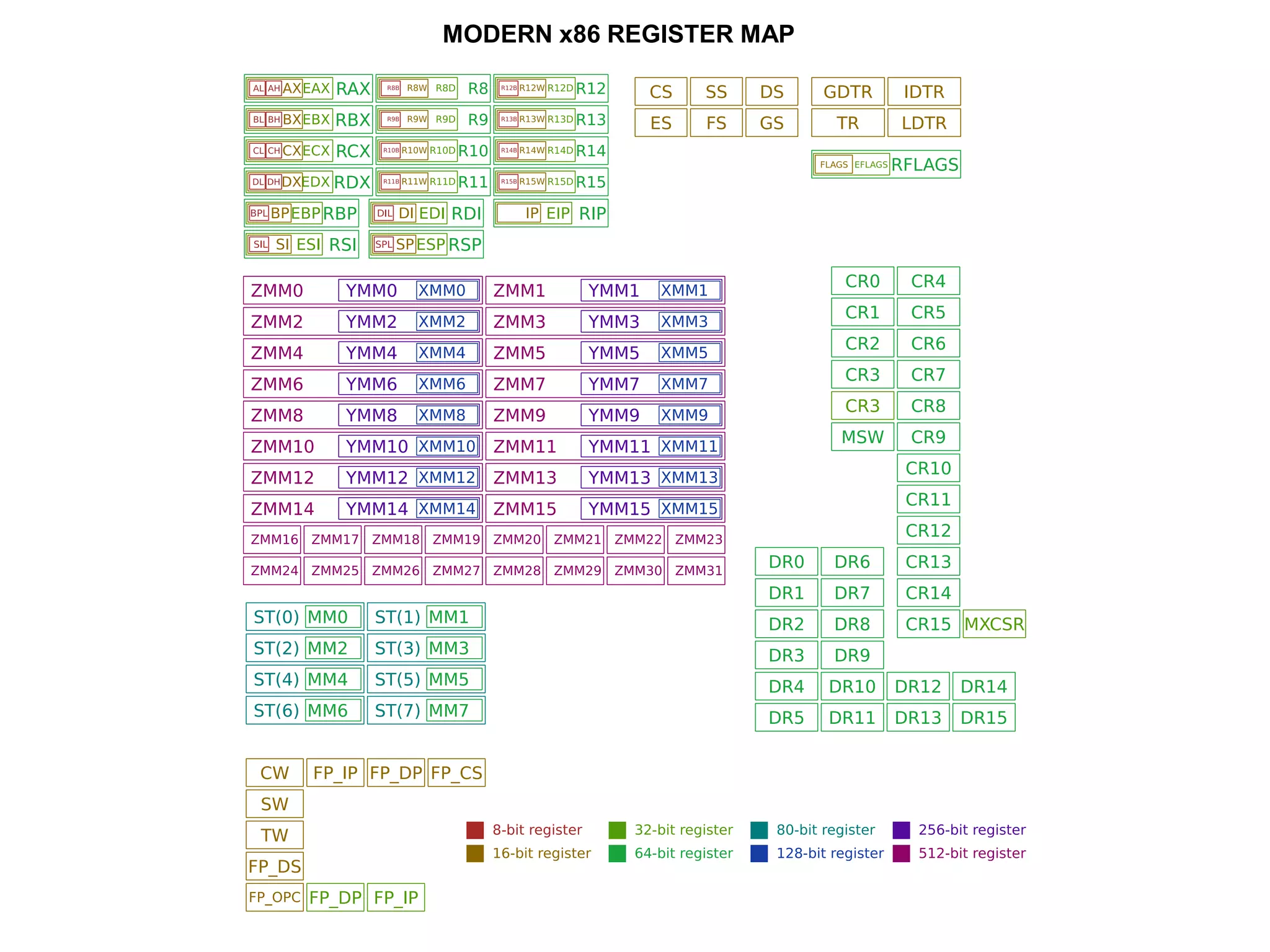
The x86 instruction set architecture began with Intel's 16-bit processors in the 1980s and has since evolved through numerous extensions. It supports multiple execution modes including 16-bit real mode, 32-bit protected mode, and 64-bit long mode. The instruction format includes optional prefixes, opcode bytes, addressing fields, and immediate data. General purpose registers are used for operands along with memory addressing modes. Subsequent x86 architectures, such as AMD64, expanded register sizes and added new instructions while maintaining backwards compatibility.